hydroboost schematic?
 05-19-2010, 08:20 PM
#1
Racer

Thread Starter
Member Since: Mar 2006
Location: Rochester New York
Posts: 326
Likes: 0
Received 0 Likes
on
0 Posts

Hi everyone,
I used to have a diagram of the hydroboost install, and have turned my place upside down trying to find it with no luck. Does anyone have a diagram? Stock '81 steering, no rack and pinion or anything. Need to know which lines go where, where the t-fitting goes, and length of hoses.
I had months of printouts of pics and posts etc and had them bound even, and now I can't find it for the life of me
Any help would be great,
Thanks!
Jeff
 05-19-2010, 09:21 PM
#2
Le Mans Master

I am not the author of this pic and can't remember where I got it, hope it helps.
http://corvettec3.ca/hydro.htm

http://corvettec3.ca/hydro.htm
Last edited by '75; 05-19-2010 at 09:25 PM.


 05-20-2010, 12:51 PM
#5
Racer
Thread Starter
Member Since: Mar 2006
Location: Rochester New York
Posts: 326
Likes: 0
Received 0 Likes
on
0 Posts
Thanks, that's actually some of the original info I had lost 
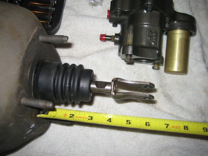
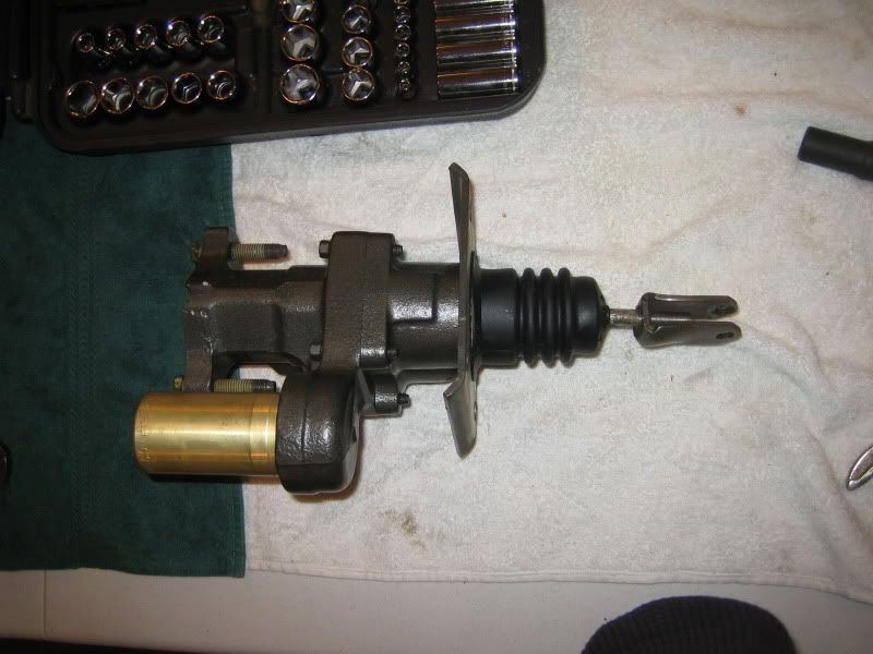
One more question: The hydroboost unit I have doesn't have threads on the shaft (for attaching the clevis pin to the brake pedal), instead it is smooth with a large tab on the end, and a hole in that tab. Can the tab be cut off, and the shaft threaded? If so, what size should I make the threads?

One more question: The hydroboost unit I have doesn't have threads on the shaft (for attaching the clevis pin to the brake pedal), instead it is smooth with a large tab on the end, and a hole in that tab. Can the tab be cut off, and the shaft threaded? If so, what size should I make the threads?
05-20-2010, 01:24 PM
#6
Pro


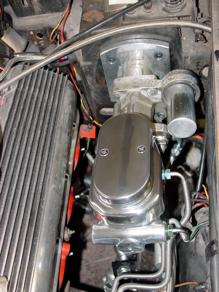
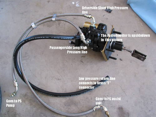
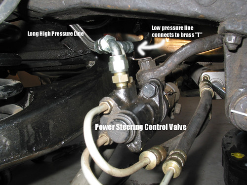
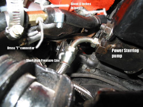
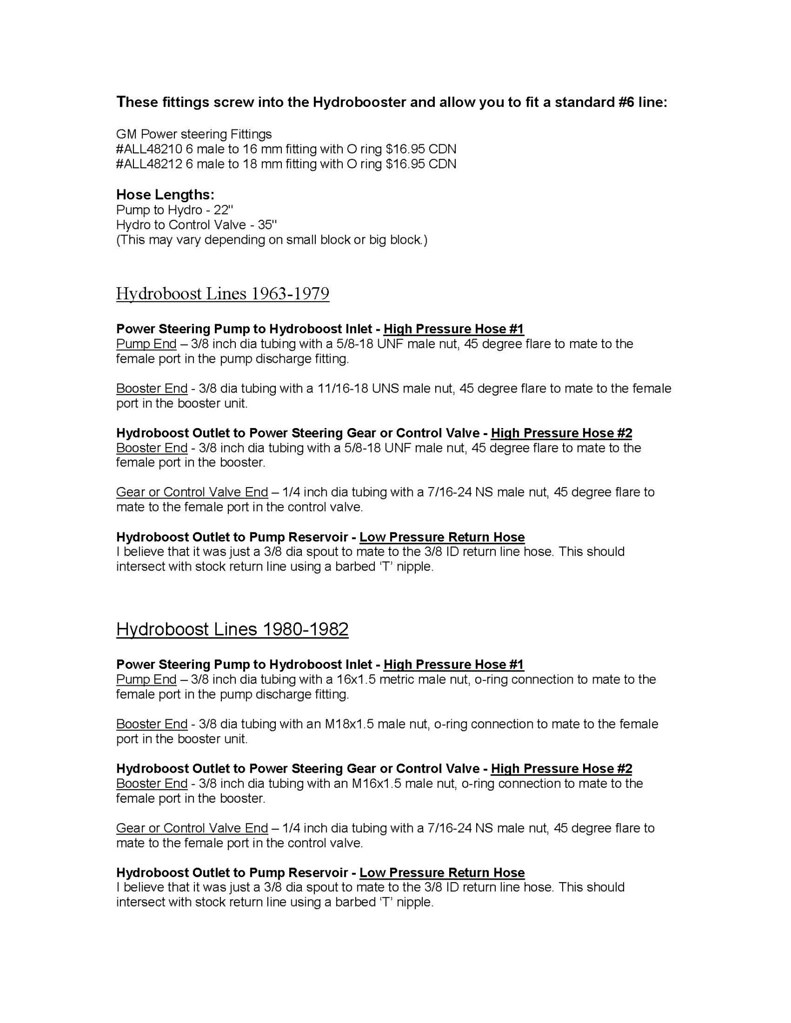
Te return lines are not under much pressure so my setup is overkill. The t-fitting can go close to the return pipe on the back of the power steering pump. Here is the return line setup on mine (high pressure fitting for pump is arriving today):
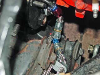
I added a filter to the system (dirt really messes up hydraulics systems) and routed all three lines along the inner fender:
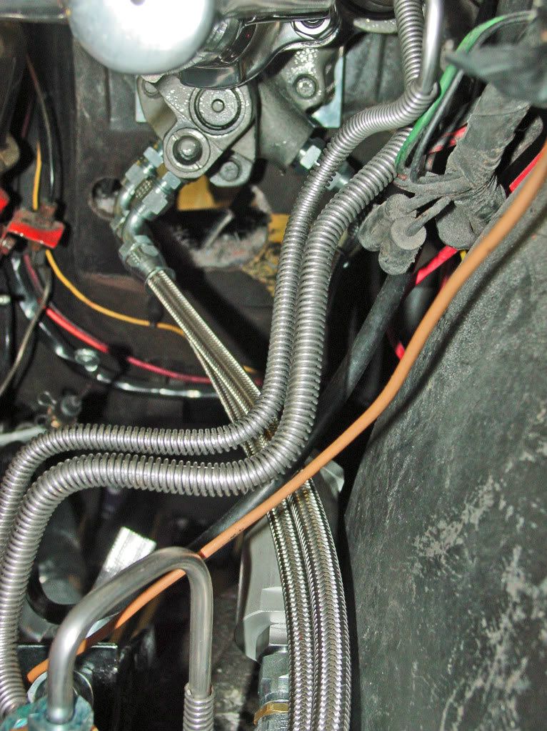
I ordered 10 feet of teflon-lined braided stainless line but I have about 3-feet leftover. Eight feet of high-pressure hose would do an entire install, even without a filter.
05-20-2010, 07:55 PM
#12
Pro

I talked to someone at Tallon Hydraulics and he advised the same thing. You don't want to try to yank that rod out of its staked hole so just cutting and threading the shaft is fine. I'd recommend a nut on the shaft as well so you can lock the clevis in the correct position.
05-21-2010, 12:29 AM
#14
Melting Slicks

Bob, I would advise against installing the filter in the line.
That will cause backpressure which may have an effect on the brake pedal. You may find the pedal not returning to its upright position as fast as it should.
They system is a loop, the filter will slow the return to the pump which will back up the entire loop. I'd be careful. All that info I read and guys i spoke to when doing my install were against filters or anything else that would restrict flow...even the T fitting restricts flow slightly which is why I added a second return on my power steering pump. A "Y" fitting might be better than a "T" fitting.
Since you have the filter already installed give it a shot, but don't take it out on the highway right away until you're sure the system is working the way you need it to for safety. Otherwise Hydro is awsome!
 05-21-2010, 09:09 AM
#15
Pro
The first diagram was mine from my install.
Bob, I would advise against installing the filter in the line.
That will cause backpressure which may have an effect on the brake pedal. You may find the pedal not returning to its upright position as fast as it should.
They system is a loop, the filter will slow the return to the pump which will back up the entire loop. I'd be careful. All that info I read and guys i spoke to when doing my install were against filters or anything else that would restrict flow...even the T fitting restricts flow slightly which is why I added a second return on my power steering pump. A "Y" fitting might be better than a "T" fitting.
Since you have the filter already installed give it a shot, but don't take it out on the highway right away until you're sure the system is working the way you need it to for safety. Otherwise Hydro is awsome!
I appreciate the recommendation. This is the first hydroboost install I�ve done and I�m trying not to screw it up (brakes are not an accessory!). I put the filter in because most hydraulic systems seem to have them (transmission, for example). With a tic under $2,000 invested in Steeroids and Hydroboost hardware, the filter seemed like cheap insurance. I thought the 12-gallon per minute flow (at 3000 psi) on this filter would be adequate. I read that the power steering pump puts out around 3 GPM at around 850 psi (constant pressure and flow from 900 RPM up).
I�m not crazy about the T-fitting (or the tube) so I�m going to put a couple of -6 bulkhead fittings in the pump reservoir. I�m going to try the system with the filter in place and if there�s any kind of problem, I�ll open the housing and take out the bronze element (then it�ll just be another accumulator). If that fixes the problem, I�ll make another line. In any case, all this work is just so I can move the car from the garage to the driveway and back while I�m prepping the body for paint and then putting in the new interior. It�s gonna be a while before it goes on the highway.
05-23-2010, 09:54 PM
#16
Pro
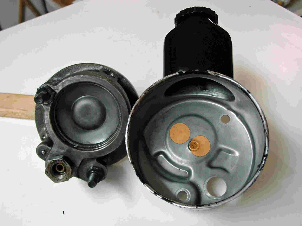
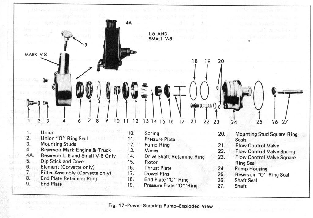
Having decided to add two return ports on the power steering pump, I decided to rebuild the pump while I had it apart. Page 9-8 in the 1972 Chevrolet Overhaul Manual has an interesting exploded view of the pump. Items 6 and 7 in the diagram show a filter unique to the Corvette pump. There was none in my pump but perhaps the Delco rebuild kit will include one. Once I opened it up, the reservoir had a coating of dark gray/black particles, very much like what I've found in the transmission pan when I change that filter.


 putting mine in next week... i will need this thread...thx!!!
05-24-2010, 12:35 AM
putting mine in next week... i will need this thread...thx!!!
05-24-2010, 12:35 AM
#18
Safety Car


Great hydroboost thread.
When you get yours, be sure to measure the old power booster clevis distance and thread your HB unit up the same or slightly closer (1/2 inch) to the HB unit. Hydratech was recommending a slightly reduced pedal height as installed so you don't feel-think your pedal is too high, since it wont move as much towards the floor as it used to, which is a good thing!!
When you get yours, be sure to measure the old power booster clevis distance and thread your HB unit up the same or slightly closer (1/2 inch) to the HB unit. Hydratech was recommending a slightly reduced pedal height as installed so you don't feel-think your pedal is too high, since it wont move as much towards the floor as it used to, which is a good thing!!
Last edited by MN-Brent; 05-24-2010 at 12:39 AM.
05-24-2010, 08:55 AM
#19
Le Mans Master


Member Since: Jul 2000
Location: Saginaw Michigan
Posts: 6,001
Likes: 0
Received 98 Likes
on
81 Posts

If you are going to braze a second return line spout on the pump reservoir, it is quite important that you locate the second spout in the correct location.

The spout shown at the 8 o'clock location can also be located just around the corner on the side of the reservoir. (Just not too far forward where it might interfere with the seal or the pump casting. Also make sure that a side spout location will not interfere with pump mounting brackets.)
Also, be sure NOT to use ordinary solder to afix the spout. The melt point of solder is too low and the spout could fall off at a critical time. You want to silver solder or copper braze the spout.
Jim
05-24-2010, 07:50 PM
#20
Pro
If you are going to braze a second return line spout on the pump reservoir, it is quite important that you locate the second spout in the correct location.
The spout shown at the 8 o'clock location can also be located just around the corner on the side of the reservoir. (Just not too far forward where it might interfere with the seal or the pump casting. Also make sure that a side spout location will not interfere with pump mounting brackets.)
Jim
The spout shown at the 8 o'clock location can also be located just around the corner on the side of the reservoir. (Just not too far forward where it might interfere with the seal or the pump casting. Also make sure that a side spout location will not interfere with pump mounting brackets.)
Jim
I'm probably headed for disaster (my usual destination) but I'm not sure those are viable options for the bungs I want to add to my Mark V8 pump housing (this is all going into a big block car).
The 8 o'clock position is too small for the -6AN bung, which looks like about 5/8-inch diameter. The sides of the housing might fit the bung but there isn't room for a 90-degree fitting (the upper A-arm is too close on the outside and the idler tension pulley is too close on the inside).
It looks like there is room in the central recess of the reservoir for two bungs. Is there some reason the normal return area can't handle the fluid from two return lines? It looks like the chamber would dampen any turbulence from the return fluid. and the two relief areas seem pretty large.