
Peripheral R.A.P. Interface & AVIC Z110BT Wiring...someone double check me please
 03-21-2010, 11:33 AM
#1
NCM Bash 2008-2018

Thread Starter
Member Since: Jul 1999
Location: Granby, MA Talladega Super Speedway Vettes 4 Vets Ambassador
Posts: 9,008
Received 75 Likes
on
60 Posts
Middle TN Events Coordinator
Cruise-In 1, 3, 9. 10 & 11 Veteran

Ok so Iam redoing my whole audio system in my vette. Iam hooking up a Peripheral R.A.P. interface into my new audio system to retain this function for my new AVIC Z110BT going into a 2002 C5 coupe.
All bose stuff removed and replaced.
All speakers removed and replaced.
Aftermarket amps being installed.
So from what it looks like to me wiring should be like this:
Peripheral R.A.P. Interface: utilizing the 3 wires under the passenger side kick panel/floor...
Yellow wire to Yellow wire. (12volt always on source)
Black wire to Black wire. (ground)
Purple wire to Orange wire (data information) on the factory radio connector.
Red wire (R.A.P. output) to the AVIC's Red wire (12 volt key/aux on source)(I think the wire was red on the AVIC...radio's out in the garage and it's raining right now lol)
AVIC Z110BT:
I moved the Yellow Pin wire on the AVIC over one spot to the left in the harness to successfully do the bypass.
Iam going to ground the light green wire and the yellow wire.
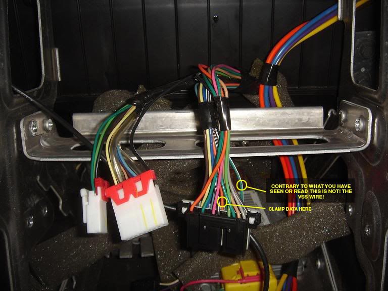
The pink wire (speed sensor wire VSS) goes to the green/white stripe wire on the factory instrument panel cluster connector. (see picture below)
Radio FM module: From what I understand I need to send 5 volts of power to the pink wire at the module behind the drivers side door. Can I use the AVICs power antenna lead to supply voltage and drop it down using the shown pictured 5 volt regulator? Do you need to do any other wiring to have the AM/FM module work? I found the link below from Markcz.
Oh yeh...If I am missing anything please anybody feel free to chime in.
Thanks
Jeff
All bose stuff removed and replaced.
All speakers removed and replaced.
Aftermarket amps being installed.
So from what it looks like to me wiring should be like this:
Peripheral R.A.P. Interface: utilizing the 3 wires under the passenger side kick panel/floor...
Yellow wire to Yellow wire. (12volt always on source)
Black wire to Black wire. (ground)
Purple wire to Orange wire (data information) on the factory radio connector.
Red wire (R.A.P. output) to the AVIC's Red wire (12 volt key/aux on source)(I think the wire was red on the AVIC...radio's out in the garage and it's raining right now lol)
AVIC Z110BT:
I moved the Yellow Pin wire on the AVIC over one spot to the left in the harness to successfully do the bypass.
Iam going to ground the light green wire and the yellow wire.
The pink wire (speed sensor wire VSS) goes to the green/white stripe wire on the factory instrument panel cluster connector. (see picture below)
Radio FM module: From what I understand I need to send 5 volts of power to the pink wire at the module behind the drivers side door. Can I use the AVICs power antenna lead to supply voltage and drop it down using the shown pictured 5 volt regulator? Do you need to do any other wiring to have the AM/FM module work? I found the link below from Markcz.
Oh yeh...If I am missing anything please anybody feel free to chime in.
Thanks
Jeff
Last edited by XtremeVette; 03-21-2010 at 08:33 PM.
 03-21-2010, 12:34 PM
#2
Le Mans Master

Member Since: Dec 2005
Location: "This is not a psychotic episode, but a cleansing moment of clarity."
Posts: 6,420
Likes: 0
Received 4 Likes
on
4 Posts

I can tell you categorically now that the green/white wire coming off the factory harness for the Bose is NOT the VSS wire and connecting your VSS to this will do nothing. Nothing good, at least. The VSS wire is in the harness connected to the instrument cluster and in order to get to it you must pull the gauge pod. I opted to pay a local installer $65 to do that part for me. I just didn't want to mess with it myself.
03-21-2010, 01:26 PM
#3
NCM Bash 2008-2018
Thread Starter
Member Since: Jul 1999
Location: Granby, MA Talladega Super Speedway Vettes 4 Vets Ambassador
Posts: 9,008
Received 75 Likes
on
60 Posts
Middle TN Events Coordinator
Cruise-In 1, 3, 9. 10 & 11 Veteran
I can tell you categorically now that the green/white wire coming off the factory harness for the Bose is NOT the VSS wire and connecting your VSS to this will do nothing. Nothing good, at least. The VSS wire is in the harness connected to the instrument cluster and in order to get to it you must pull the gauge pod. I opted to pay a local installer $65 to do that part for me. I just didn't want to mess with it myself.
"It is known YES, that the VSS wire is located under the dash", however many have claimed to have found it on the green/white wire". I was hoping to get some input from the guys that have found it successfully on the bose radio connector or one of the 2 other plugs that also go into the original head unit.
Iam aware of the process to remove the cluster. I have done this many times and is no big deal to myself. I was just hoping to find the connection somewhere in the radio area instead of removing even more pieces.

In case the cluster area is all there is....What wire under the dash/cluster area is the VSS. A picture would be great.
Thanks
Last edited by XtremeVette; 03-21-2010 at 01:30 PM.
03-21-2010, 01:36 PM
#4
Le Mans Master
Member Since: Dec 2005
Location: "This is not a psychotic episode, but a cleansing moment of clarity."
Posts: 6,420
Likes: 0
Received 4 Likes
on
4 Posts
Ok Iam sorry I should have added...
"It is known YES, that the VSS wire is located under the dash", however many have claimed to have found it on the green/white wire". I was hoping to get some input from the guys that have found it successfully on the bose radio connector or one of the 2 other plugs that also go into the original head unit.
Iam aware of the process to remove the cluster. I have done this many times and is no big deal to myself. I was just hoping to find the connection somewhere in the radio area instead of removing even more pieces.
In case the cluster area is all there is....What wire under the dash/cluster area is the VSS. A picture would be great.
Thanks
Here is a pic that McGilles took of the VSS connection at the harness behind the gauges.

Here is the rest of McGilles install post. http://forums.corvetteforum.com/c5-g...etup-pics.html
Last edited by JMc; 03-21-2010 at 05:07 PM.
03-21-2010, 03:48 PM
#5
NCM Bash 2008-2018
Thread Starter
Member Since: Jul 1999
Location: Granby, MA Talladega Super Speedway Vettes 4 Vets Ambassador
Posts: 9,008
Received 75 Likes
on
60 Posts
Middle TN Events Coordinator
Cruise-In 1, 3, 9. 10 & 11 Veteran
Here is the real VSS wire!
Okay, just to reiterate, there is not VSS wire on the Bose connector or anywhere near the radio area. The photo you show in your first post showing the VSS on the radio harness connector is INCORRECT.
Here is a pic that McGilles took of the VSS connection at the harness behind the gauges.
Here is the rest of McGilles install post. http://forums.corvetteforum.com/c5-g...etup-pics.html
Here is a pic that McGilles took of the VSS connection at the harness behind the gauges.
Here is the rest of McGilles install post. http://forums.corvetteforum.com/c5-g...etup-pics.html
Last edited by XtremeVette; 03-21-2010 at 08:47 PM.
03-21-2010, 04:14 PM
#6
Tech Contributor
 There may be some who THINK they found the wire at the radio, but none actually have.
Look again, the pink wire is the added wire, the green/white is the stock wire.
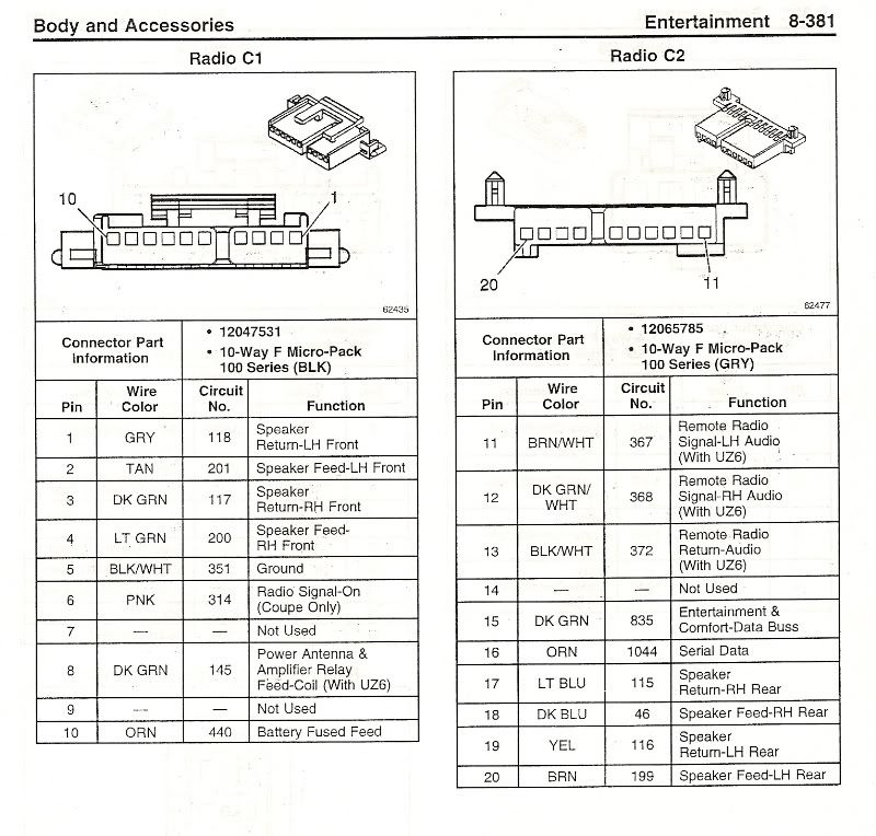
In your own post you put a pic of the radio plugs. Circuit 368 is the RH audio signal, it has NOTHING to do with VSS.
 03-21-2010, 05:03 PM
#7
Le Mans Master
Member Since: Dec 2005
Location: "This is not a psychotic episode, but a cleansing moment of clarity."
Posts: 6,420
Likes: 0
Received 4 Likes
on
4 Posts
Thanks, Mark. I was really starting to get tired of arguing with this guy. He asked for someone to double check, someone did (me), and all he wants to do is argue. 
Jeff, believe me, I would have LOVED for the VSS wire to be in a handy spot to get to. I just installed my Z110BT a week ago, but I researched it here, found the same bogus information, had it clearly disproved by Mark and others and went ahead with the installation, having the VSS connected behind the cluster, which my installer also confirmed as being where the wire is.
Jeff, believe me, I would have LOVED for the VSS wire to be in a handy spot to get to. I just installed my Z110BT a week ago, but I researched it here, found the same bogus information, had it clearly disproved by Mark and others and went ahead with the installation, having the VSS connected behind the cluster, which my installer also confirmed as being where the wire is.
Last edited by JMc; 03-21-2010 at 05:12 PM.
03-21-2010, 05:25 PM
#8
NCM Bash 2008-2018
Thread Starter
Member Since: Jul 1999
Location: Granby, MA Talladega Super Speedway Vettes 4 Vets Ambassador
Posts: 9,008
Received 75 Likes
on
60 Posts
Middle TN Events Coordinator
Cruise-In 1, 3, 9. 10 & 11 Veteran
sorry wasn't trying to argue with either of ya lol. Markcz has been giving me great information via PM's.
Not sure if what I said was confusing...The pink wire is the speed sensor from the AVIC and it was tapped into circuit 817 (green/white wire) from the gauge cluster. That is what I was trying to explain. I just found it oddly funny that the green/white wire on the cluster was the same exact color combination from the image that I found on here from another guy who posted it. It must of been purely coincidental. It could of also been quite possibly that the person who posted that image who believed he had found the VSS wire there just got confused as to what harness he should of been "tapping" into and thus how the whole "bad information" thingy originated in the first place. No harm no foul to anybody and that true VSS on circuit 817 on the instrument cluster is no big deal to all those saying "oh man I have to remove my cluster?". Takes all of maybe 25 minutes to do or 15 if you have removed it enough times like myself.
Anybody have any information regarding the antenna module?
Thanks
Jeff
Last edited by XtremeVette; 03-21-2010 at 08:41 PM.
03-21-2010, 05:28 PM
#9
NCM Bash 2008-2018
Thread Starter
Member Since: Jul 1999
Location: Granby, MA Talladega Super Speedway Vettes 4 Vets Ambassador
Posts: 9,008
Received 75 Likes
on
60 Posts
Middle TN Events Coordinator
Cruise-In 1, 3, 9. 10 & 11 Veteran
Or the R.A.P.!!! I said "screw that" when I saw the schematics for that power source! Thanks again to Markcz. I went and found the module on a certain auction site for $25 shipped! I couldn't pass it up as it was half priced! lol
So basically Markcz is saying the volume control on the radio is handled differently then the VSS.
Very good to know!
I have to agree with others that the radio itself must have a VSS signal coming in somewhere as the radio itself adjusts the volume depending upon speed so it must get a VSS signal. For those thinking this like myself...here is an answer that I have never read before so to others here ya go:
The stock radio listens in on the serial data line. It gets the speed from data sent over that line.
The stock radio listens in on the serial data line. It gets the speed from data sent over that line.
Very good to know!
Last edited by XtremeVette; 03-21-2010 at 08:42 PM.
03-21-2010, 06:03 PM
#10
Le Mans Master
But the orange wire from the first picture IS the Data wire? Is that where I can hook my data wire from my GMRAP?
Last edited by Paul 75 L82; 03-21-2010 at 06:04 PM. Reason: more info
03-21-2010, 07:22 PM
#11
NCM Bash 2008-2018
Thread Starter
Member Since: Jul 1999
Location: Granby, MA Talladega Super Speedway Vettes 4 Vets Ambassador
Posts: 9,008
Received 75 Likes
on
60 Posts
Middle TN Events Coordinator
Cruise-In 1, 3, 9. 10 & 11 Veteran
BUT be sure it is the one pictured...6 in from the side of the connector! NOT the one in the black connector on the far left side...that one is a battery fused feed you don't want it.I edited this picture (as well as the one above) for those following this post so that NO mis-communication happens! The VSS wire is pictured above!
Last edited by XtremeVette; 03-21-2010 at 08:45 PM.
03-21-2010, 07:30 PM
#12
NCM Bash 2008-2018
Thread Starter
Member Since: Jul 1999
Location: Granby, MA Talladega Super Speedway Vettes 4 Vets Ambassador
Posts: 9,008
Received 75 Likes
on
60 Posts
Middle TN Events Coordinator
Cruise-In 1, 3, 9. 10 & 11 Veteran
Iam still hoping Markczm Pentavolvo or anyone can chime in and can PLEASE VERIFY ALL CONNECTIONS FOR BOTH THE BENEFIT OF MYSELF AND EVERYBODY ELSE FOLLOWING THIS THREAD along with add input on the FM module box.
This is so far everything I have read on the subject along with the route I think Iam going to take:
Quoting Markcz from another post found:
From another post from within Marks thread:
Thanks to Mark again....pins for the voltage regulator are this:
Left Pin=INPUT or 12 volt power antenna spliced lead
Center Pin=GROUND
Right Pin=OUTPUT 5 volt power to the PINK wire on the FM module that is located behind the driver seat on the side pillar (behind the plastic that goes around the seatbelt)
Be sure to properly mount the regulator and wrap all connections securely with electrical tape and/or wire sleeves so that no short circuits happen.
Thanks
Jeff
Radio FM module: From what I understand I need to send 5 volts of power to the pink wire at the module behind the drivers side door. Can I use the AVICs power antenna lead to supply voltage and drop it down using the shown pictured 5 volt regulator? Do you need to do any other wiring to have the AM/FM module work? I found the link below from Markcz.
Quoting Markcz from another post found:
I wired in my cell phone charger to the antenna module, and it does seem to help, especially on AM. While I was experimenting, with the module OFF and the radio ON, I unplugged the antenna plug that supplies the radio, and reception almost went away completely, so I believe that the module just acts as a fancy "Y" connector for the two antennas if it isn't powered, so attempting to bypass it wouldn't do much good.
The charger I used is a Belkin Mobile Power Cord for Audiovox/Kyocera/LG/Samsung/Sanyo that I got at Wal-Mart. I also used a Car Power Adapter with Battery Clips that I cut the clips off of.
Here are some pics of the module before - during - and after the mod.
For the power plug, I spliced into the green wire for the + cord, and used the grounding bolt just above the module as the ground.
The cell phone charger plugs into the power plug.
I used a multimeter to determine that the red wire at the output of the charger was the +5VDC, then spliced that wire into the pink wire going to the antenna module. I didn't connect the white ground wire to anything, it's just taped up. NOTE: This assumes that nothing is connected to the pink wire at the plug where it went into the original Delco/Bose HU, if you ever reinstall the stock HU this mod must be removed first!
Cover everything important with tape, add a few zip ties, put the car back together, and enjoy your aftermarket radio. Just don't decide to vacuum your carpet afterwards and suck up two of the four seat mounting nuts, the inside of a shop vac can be messy
A much simpler solution than splicing in a cell phone adapter is to go to Radio Shack and buy a $2 voltage regulator part #276-1770.
This IC circuit will reduce the 12 VDC to 5 VDC and is the size of a dime. 5 volts is the standard trigger voltage in car applications. Split the power antenna lead on the aftermarket head unit, attach one lead to the dark green wire in the wire loom, attach the other lead to the IC circuit input, and run the output lead from the IC circuit to the pink wire in the wire loom and it should work just fine. You might want to screw the IC circuit to a piece of metal around the head unit for a heat sink, and shrink tube the power leads to avoid any shorts.
I will try this soon, since I will be changing to an aftermarket head unit, and I can't tell you HOW HAPPY I AM TO HAVE SEEN THIS POST BEFORE I HAD THE PROBLEM!!!!!!!!!!!
Here is the part: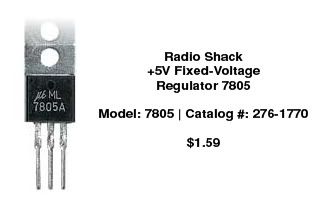
Left Pin=INPUT or 12 volt power antenna spliced lead
Center Pin=GROUND
Right Pin=OUTPUT 5 volt power to the PINK wire on the FM module that is located behind the driver seat on the side pillar (behind the plastic that goes around the seatbelt)
Be sure to properly mount the regulator and wrap all connections securely with electrical tape and/or wire sleeves so that no short circuits happen.
Thanks
Jeff
Last edited by XtremeVette; 03-21-2010 at 08:54 PM.
03-21-2010, 08:36 PM
#14
NCM Bash 2008-2018
Thread Starter
Member Since: Jul 1999
Location: Granby, MA Talladega Super Speedway Vettes 4 Vets Ambassador
Posts: 9,008
Received 75 Likes
on
60 Posts
Middle TN Events Coordinator
Cruise-In 1, 3, 9. 10 & 11 Veteran
Thanks! Iam trying hard to make this thread as thorough as possible so that anybody installing an AVIC Z110BT or for the most part any aftermarket nav radio will be able to find all the correct information in one simple thread. For anybody following this thread has read & seen, there are many threads out there with valuable information here and there and in some cases bogus information as well.
03-21-2010, 08:40 PM
#15
Tech Contributor
Before implementing the 7805 IC voltage regulator you will need to recognize where the leads are on it. To do the you will want to sit it where you can read the print on the top of it facing you. The pin sticking out of it on the left is the input, the pin on the right is the output, and the one in the middle is the ground.
03-27-2010, 10:07 AM
#17
Melting Slicks

Yes, thank you very much as I also just received my Z110 yesterday and want the installer to hook up the VSS. I am also researching the best location for the GPS and XM antennas and the mike. I see where one forum member mounted the GPS on top of the HU under the dash and the XM antenna on the windshield up on the shaded part by the right side post. Don't know how well these locations will work though for the antennas but they are nice locations for hiding them. Looks like I can mount the mike on the driver side visor and run the wire down the left side post. Hopefully there will be enough wire for this. Do you see any problems with these locations?
03-27-2010, 10:16 AM
#18
Tech Contributor
Nav antenna can pretty much be anywhere, inside dash is fine. Sat radio is a bit picky, so high on the windshield is a good choice. I had mine on top of the rear bumper (inside fascia) in my C5 and it worked pretty good, but not as good as if it were on the windshield.
03-27-2010, 03:43 PM
#19
Melting Slicks
Tried the XM antenna up high on the windshield next to the A pillar and I lost signal several times going around the block but others have had luck with this location. It might be that I had it inverted but it looked ugly on the underside which would be exposed that way. I moved it back down to the bottom of the windshield on top of the dash next to the A pillar.
03-28-2010, 11:03 AM
#20
Pro

Member Since: Jun 2000
Location: Granby MA
Posts: 706
Likes: 0
Received 1 Like
on
1 Post
Cruise-In I Veteran
Cruise-In II Veteran
Ok so do you tie the 12 volt constant yellow wire to the same 12 volt sources for the RAP interface and the AVIC? In other words:
12 volt constant yellow wire under passenger foot well goes to both the AVIC 12 volt constant wire (for the memories) AND to the RAP yellow wire (as the RAP is asking for a 12 volt constant source.)
Data purple wire to the orange wire on the factory radio connector.
Black wire ground to ground wire.
then
AVIC:
Red wire from the RAP (accessory RAP output) to the red wire (accessory on only) on the AVIC.
Parking brake, yellow wire from the pin that was moved & the light green wire....ground them.
Reverse wire...don't need, not running a backup camera.
VSS pink wire to the light green/white stripe wire next to the tan wire on the instrument panel cluster plug.
Blue 12 volt power antenna wire to the voltage regulator to the pink wire on the antenna booster wire behind the drivers seat.
Last edited by Blackout; 03-28-2010 at 11:07 AM.