
Low Buck C5 Front Brake Ducts.....50 bucks
 01-08-2008, 11:27 PM
#1
Melting Slicks


Thread Starter

Low Buck Front Air Ducts…..for 50 bucks and some time
Not being a hard core tracker or racer, I’m looking for the best “Bang for the Buck” when it come to adding mods to my car. Catching the buzz about using C6-Z front ducts on a C5 for a bunch less $$$ than the popular DRM/LG method, I thought I would give it a try. I ordered my ducts from Fred Bean’s for less than $25 delivered to the house.
First, I removed all the fasteners holding the front bumper in place along with removing the small front inner fender panel. Do NOT remover the bumper; you will need to have it in place for correct joining of the old and new ducts. Next remove the stock C5 front air ducts from between the bumper and inner finder. You’ll need to pull the bumper out away from the bottom to do this.
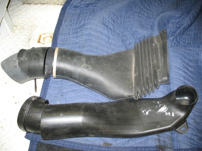
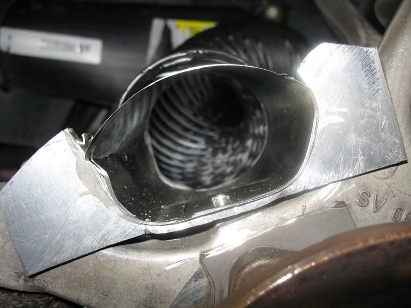
As shown in the photo, you will have to remove about two or three inches from each duct. A band saw works very well for this if you have one. Basically, you will cut the ducts at the end of the straight portion just before the last bend.
After cutting the ends off, one duct will now slide inside of the other. I used a 4” sheet metal vent coupling from Home Depot ($2.50) and two hose clamps to reinforce the splice. The sheet metal coupling has a hump in the center with about 3” of sleeve on either side. I used a cutoff wheel to remove the upset in the center, and then removed the rivets in each straight piece leaving something looking like a muffler patch.
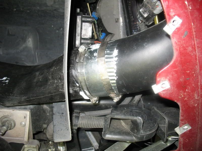
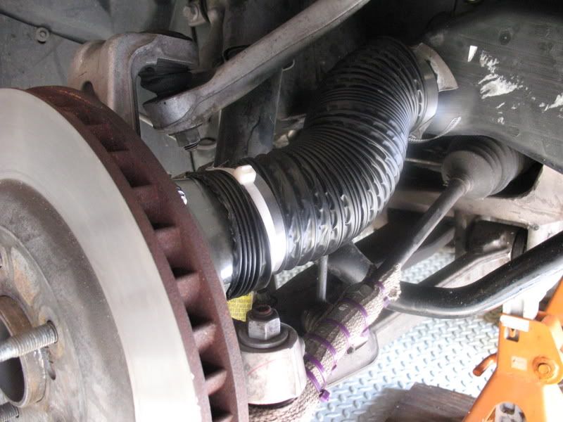
Using some handy goop (some kind of sealant) from my shop, I ran a bead on the inside of the larger duct before sliding the smaller one in place. This will have to be done with the front duct inside of the bumper (bumper needs to be in its proper position) and the new extension piece inserted from the fender well. Now place the intake end in its proper position just inside the front bumper, using some force to collapse the bellows slightly and with the other hand, stretch out the new section so the outlet is against the sock mounting tower as in the photo. If I were hard core, I would trim the corner of the shock mount to gain another 1/4 to 1/2 inch extension. After getting the proper alignment/length established, add some more goop to the muffler clamp and apply over the splice with two hose clamps.
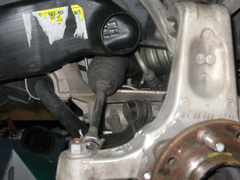
NOTE: The position of the inner duct outlet needs to be as low as possible without hitting the steering linkage or boot (with suspension in compressed position). I think I may have been able to lower mine another ˝” or so without hitting. My front track tires are 305-30x18’s on stock rear C5-Z rims (10.5 wide) and they will just hit the hose/outlet duct with the inner wheel at 1 ˝ turns from center (stops are at 1 ľ turns). At this point the outer edge of the tire is about to hit the body of the duct, just like the high priced ducts. I do not see this as much of a problem because the only time you will ever turn this sharp is in the pits. On the track you will seldom use more than a half turn off of center (unless you’re in deep $h!t).
Now a mount for the spindle needs to be made to attach the hose outlet. For this I started with a pair of scissors and a sheet of stiff paper, making a flat pattern, bending and trimming, then transferring the pattern to a piece of 10 ga. Aluminum. I cut the piece out with the band saw, bent it up using a bench vice and a hammer, then more trimming a fitting until it fit.
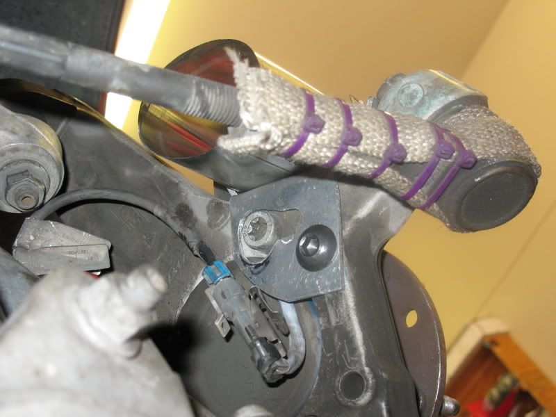
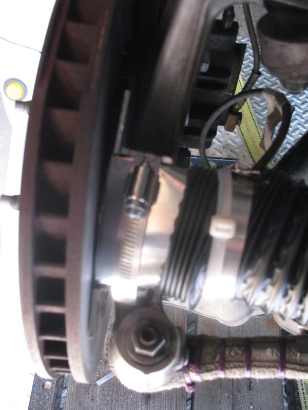
Now the search for some tubing, 2 5/8” in dia. to attach the outer end of the hose and duct the air into the rotor. I couldn’t find anything at Home Depot, so I settled on using an aerosol can (most of your paint/aerosol cans just happen to be the correct size, matching the outlet size of the new C6-Z duct). Using a hose clamp to hold the tubing to the new spindle mount, I also used a pop rivet through the clamp, alum. mount and tubing for extra security. To hold the mount in place, I tapped the upper of the two blank holes for a ˝-13 bolt (the hole just happens to be close enough in dia. to tap). You will have to trim the mounting tab to clear the upper spindle bolt head as seen in photo. I also had to remove the brackets that hold the ABS wiring connectors with my cutoff wheel. Later I used a zip tie to hold the connectors in place.


2 5/8” vent hose is tuff to find so I settled for 3” from Auto Zone (6 ft. for $15). This worked out well because it gave me plenty of space to use some 3M double stick tape between the spindle tubing and hose & the outlet duct/hose. Should the hose clamp come loose, the tape should take over and keep everything in place.
Bottom Line; for about 50 bucks and a few hours after work you can have some much needed air to your front brakes for those track days. Now before anyone says anything about airflow, yes, the low buck ducts are a half inch smaller in diameter than the high buck ones. BUT I did do a non-scientific test using my box fan in front of the air intakes and I COULD feel air coming out of the rotor vanes. THAT’S GOOD ENOUGH FOR ME!
Not being a hard core tracker or racer, I’m looking for the best “Bang for the Buck” when it come to adding mods to my car. Catching the buzz about using C6-Z front ducts on a C5 for a bunch less $$$ than the popular DRM/LG method, I thought I would give it a try. I ordered my ducts from Fred Bean’s for less than $25 delivered to the house.
First, I removed all the fasteners holding the front bumper in place along with removing the small front inner fender panel. Do NOT remover the bumper; you will need to have it in place for correct joining of the old and new ducts. Next remove the stock C5 front air ducts from between the bumper and inner finder. You’ll need to pull the bumper out away from the bottom to do this.
As shown in the photo, you will have to remove about two or three inches from each duct. A band saw works very well for this if you have one. Basically, you will cut the ducts at the end of the straight portion just before the last bend.
After cutting the ends off, one duct will now slide inside of the other. I used a 4” sheet metal vent coupling from Home Depot ($2.50) and two hose clamps to reinforce the splice. The sheet metal coupling has a hump in the center with about 3” of sleeve on either side. I used a cutoff wheel to remove the upset in the center, and then removed the rivets in each straight piece leaving something looking like a muffler patch.
Using some handy goop (some kind of sealant) from my shop, I ran a bead on the inside of the larger duct before sliding the smaller one in place. This will have to be done with the front duct inside of the bumper (bumper needs to be in its proper position) and the new extension piece inserted from the fender well. Now place the intake end in its proper position just inside the front bumper, using some force to collapse the bellows slightly and with the other hand, stretch out the new section so the outlet is against the sock mounting tower as in the photo. If I were hard core, I would trim the corner of the shock mount to gain another 1/4 to 1/2 inch extension. After getting the proper alignment/length established, add some more goop to the muffler clamp and apply over the splice with two hose clamps.
NOTE: The position of the inner duct outlet needs to be as low as possible without hitting the steering linkage or boot (with suspension in compressed position). I think I may have been able to lower mine another ˝” or so without hitting. My front track tires are 305-30x18’s on stock rear C5-Z rims (10.5 wide) and they will just hit the hose/outlet duct with the inner wheel at 1 ˝ turns from center (stops are at 1 ľ turns). At this point the outer edge of the tire is about to hit the body of the duct, just like the high priced ducts. I do not see this as much of a problem because the only time you will ever turn this sharp is in the pits. On the track you will seldom use more than a half turn off of center (unless you’re in deep $h!t).
Now a mount for the spindle needs to be made to attach the hose outlet. For this I started with a pair of scissors and a sheet of stiff paper, making a flat pattern, bending and trimming, then transferring the pattern to a piece of 10 ga. Aluminum. I cut the piece out with the band saw, bent it up using a bench vice and a hammer, then more trimming a fitting until it fit.
Now the search for some tubing, 2 5/8” in dia. to attach the outer end of the hose and duct the air into the rotor. I couldn’t find anything at Home Depot, so I settled on using an aerosol can (most of your paint/aerosol cans just happen to be the correct size, matching the outlet size of the new C6-Z duct). Using a hose clamp to hold the tubing to the new spindle mount, I also used a pop rivet through the clamp, alum. mount and tubing for extra security. To hold the mount in place, I tapped the upper of the two blank holes for a ˝-13 bolt (the hole just happens to be close enough in dia. to tap). You will have to trim the mounting tab to clear the upper spindle bolt head as seen in photo. I also had to remove the brackets that hold the ABS wiring connectors with my cutoff wheel. Later I used a zip tie to hold the connectors in place.
2 5/8” vent hose is tuff to find so I settled for 3” from Auto Zone (6 ft. for $15). This worked out well because it gave me plenty of space to use some 3M double stick tape between the spindle tubing and hose & the outlet duct/hose. Should the hose clamp come loose, the tape should take over and keep everything in place.
Bottom Line; for about 50 bucks and a few hours after work you can have some much needed air to your front brakes for those track days. Now before anyone says anything about airflow, yes, the low buck ducts are a half inch smaller in diameter than the high buck ones. BUT I did do a non-scientific test using my box fan in front of the air intakes and I COULD feel air coming out of the rotor vanes. THAT’S GOOD ENOUGH FOR ME!

 01-09-2008, 01:23 AM
#4
Melting Slicks


Not bad for $50, and some good handy work. On street tires, or on tracks that aren't too brake-intensive they should cut it (assuming you're using the right pads, right fresh fluid etc). But the C6Z style duct opening is soooooo much smaller than the DRM style duct. I actually have a set of both sitting in the garage right now, I'll snap a few pics later for comparison.
-TJ
-TJ
01-09-2008, 03:18 AM
#5
Team Owner

Not bad for $50, and some good handy work. On street tires, or on tracks that aren't too brake-intensive they should cut it (assuming you're using the right pads, right fresh fluid etc). But the C6Z style duct opening is soooooo much smaller than the DRM style duct. I actually have a set of both sitting in the garage right now, I'll snap a few pics later for comparison.
-TJ
-TJ
 01-09-2008, 07:33 AM
#6
Melting Slicks
Thread Starter
Not bad for $50, and some good handy work. On street tires, or on tracks that aren't too brake-intensive they should cut it (assuming you're using the right pads, right fresh fluid etc). But the C6Z style duct opening is soooooo much smaller than the DRM style duct. I actually have a set of both sitting in the garage right now, I'll snap a few pics later for comparison.
-TJ
-TJ

As far as the Zip Tie; the thought crossed my mind about the heat but if you'll notice the Zips on the Rod End......they have been on for over a year..=..10 track days. An EZ upgrade if needed

BTW....I'm running PFC 01's, Motul 600, SS lines.......the basic good stuff.
01-09-2008, 08:18 AM
#7
Team Owner
3" dia for DRM Vs 2 1/2" for the 6-Z's, no argument........but just what does that realty equate to in air flow? Remember that the opening/outlet of the tube feeding the air to the rotors needs to be squished down to direct max air flow into the vanes, loosing sq. in.'s of area. Taking a stab in the dark, I maybe loosing 30% (air flow) Vs DRM's??? That's still 70% more than I had @ 25% of the cost
As far as the Zip Tie; the thought crossed my mind about the heat but if you'll notice the Zips on the Rod End......they have been on for over a year..=..10 track days. An EZ upgrade if needed
BTW....I'm running PFC 01's, Motul 600, SS lines.......the basic good stuff.
As far as the Zip Tie; the thought crossed my mind about the heat but if you'll notice the Zips on the Rod End......they have been on for over a year..=..10 track days. An EZ upgrade if needed
BTW....I'm running PFC 01's, Motul 600, SS lines.......the basic good stuff.
 01-09-2008, 11:16 AM
#9
Melting Slicks

Here are both right side units, C6Z on the left DRM on the right.
I didn't bother to measure both (I can later, have to leave for the office soon) but it sure looks like bigger than a .5" difference. Also, in a cylindrical object I don’t believe airflow holds a linear relationship to diameter. That is to say the roughly 20% increase in diameter of the opening (if they are indeed 2.5” and 3”) should account for greater than a 20% increase in airflow. Of course, these aren’t simple cylinders. As John mentioned it’s the “kink” where they flatten out for tire clearance and then turn out towards the wheel that is very restrictive in a C6Z duct. Again, I didn’t measure these sections but maybe I will later. The visual difference is pretty obvious in the (camera phone) picture though.
-TJ
PS- 3 bonus car-guy points for whoever names the motor they’re sitting on first.
Last edited by tjZ06; 01-09-2008 at 11:20 AM.
01-09-2008, 11:19 AM
#10
Melting Slicks
 01-09-2008, 11:24 AM
#11
Melting Slicks
Yeah... it's one of those things that holds space in the front of a FD RX7 'til somebody puts a LSX in there. Them thar MazDUH boys call 'em 13Bs. Oh, but the owner says no points for you because you spelled "rotary" wrong.
-TJ
Them thar MazDUH boys call 'em 13Bs. Oh, but the owner says no points for you because you spelled "rotary" wrong. -TJ
01-09-2008, 12:14 PM
#13
Drifting

I like the homebrew setup. Real nice improvisation that will likely hold together on the track. I have been looking hard at the new Z ducts myself. The theory is that some directed air flow is better than none, and it'll likely be good enough to extend brake component life and useful braking during a session. Nice work!
01-09-2008, 01:45 PM
#14
Instructor


Member Since: Aug 2004
Posts: 161
Likes: 0
Received 0 Likes
on
0 Posts

If you cut the ends off both sides of the air duct (the one on the car and the new extension) the extension will fit inside of the air duct on the car (you will need to trim a little). They fit so tight there is no air leak. The overlap of the two ends make it easy to fit up also. I didn’t even have to modify the hole in the fender. 2003 C5
01-09-2008, 06:58 PM
#15
Melting Slicks
Thread Starter
I didn't bother to measure both (I can later, have to leave for the office soon) but it sure looks like bigger than a .5" difference. Also, in a cylindrical object I don’t believe airflow holds a linear relationship to diameter. That is to say the roughly 20% increase in diameter of the opening (if they are indeed 2.5” and 3”) should account for greater than a 20% increase in airflow. Of course, these aren’t simple cylinders. As John mentioned it’s the “kink” where they flatten out for tire clearance and then turn out towards the wheel that is very restrictive in a C6Z duct. Again, I didn’t measure these sections but maybe I will later. The visual difference is pretty obvious in the (camera phone) picture though.
-TJ
PS- 3 bonus car-guy points for whoever names the motor they’re sitting on first.[/QUOTE]
I agree....that looks bigger than 3" in the photo. Again, if your hard core and or running major HP...go for the DRM's, you need-um. For us "Want-A-Be" stock weekend racers on a budget, I throw this setup out as a viable option.
John; you are correct about deforming/restricting flow at the outlet. In my mind, blowing air on the back side of the rotor isn't all bad, but that's not the side that needs it most. All or most of your heat cracks are on the outboard side. I chose to funnel as much flow as possible to the air intake area of the rotor......aiming to put the cooling to where it is needed the most.
01-09-2008, 07:04 PM
#16
Team Owner
My rotors were so hot once and I cam in and parked the car to check tire temps, big mistake. Hot air reversed and blew back in towards the DRM ducts and they just about collapsed.
01-09-2008, 09:59 PM
#17
HISVETT,
Great "how to", I knew there was a less expensive way to cool the brakes with out going to the DRM system. Do you happen to have the GM part number for the C6 brake ducts?
Great "how to", I knew there was a less expensive way to cool the brakes with out going to the DRM system. Do you happen to have the GM part number for the C6 brake ducts?
03-12-2008, 06:01 AM
#19
Team Owner
except they flow a lot less air than DRM ducts so your brakes and wheelbearings will be hotter and rotors and pads will wear faster. So a savings is not always a savings.
03-12-2008, 06:37 AM
#20
Here is some info I got from Gene Culley
"I sell the C6 Z06 front brake ducts for 6.98 each. If you'd like to order
them you can go to the front page at www.gmpartshouse.com. Click where it
says gm part number search. Use part numbers 15829066 and 15829067 under Chevrolet make."
"I sell the C6 Z06 front brake ducts for 6.98 each. If you'd like to order
them you can go to the front page at www.gmpartshouse.com. Click where it
says gm part number search. Use part numbers 15829066 and 15829067 under Chevrolet make."