
Flaming River Emerg shutoff switch
 06-07-2008, 04:10 PM
#1
Melting Slicks

Thread Starter

I have an LT4 that I installed a Flamig River Emerg Shut off switch but I do not know where to connect to the coil. I have tried both the green wire (Flaming River suggests/guess) and it will not start. I have tried the pink and nothing happens. I am lost and would like some help. I have sent the wire diagram to Flaming River but it has not worked out.
Maybe the pink/blk on the Ign Module ?????
Maybe the pink/blk on the Ign Module ?????
Last edited by vstol; 06-12-2008 at 07:01 AM.
 06-07-2008, 06:08 PM
#2
Le Mans Master


"Flaming River Emerg Shutoff Switch" - now that's an evocative topic title.
Has information come to your attention suggesting that the coil be in
the shut-off circuit?
My understanding is that with an emergency shut-off, the object is to
cut the battery and in the case where a 4-pole switch is used, cut the
alternator so that a running engine can not continue to provide current
even though the battery has been disconnected.
We used a Cole-Hersee 4-pole switch on a non-EFI car of mine. Here
is a link to product info that includes a schematic
.
06-07-2008, 08:16 PM
#3

Slalom's right as usual. Shutting the switch off kills your entire electrical system and grounds the alternator output ( which usually requires a 3 ohm resister). Some switches have this resister built in, some are external.
When this switch is thrown, the coil is already without power, so no reason for this typr of switch to have wires going to the coil.
Did you buy this switch used? The green and pink wires are confusing since all of FR's switches have 4 posts with nuts (2 large ,2 small).
When this switch is thrown, the coil is already without power, so no reason for this typr of switch to have wires going to the coil.
Did you buy this switch used? The green and pink wires are confusing since all of FR's switches have 4 posts with nuts (2 large ,2 small).
06-07-2008, 08:22 PM
#4
Melting Slicks
Thread Starter
thanks, the switch is new and what has puzzled me is both the directions and the boys at Flamingriver say to the coil. I also thought to go to the alt. The green and pink are the coiil wires and it is a 4 post 
06-07-2008, 09:59 PM
#5
Le Mans Master
However, consider that they only appear to offer two battery shut off
products that have four poles:
- Combination Battery & Alternator Kill Switch


- Magneto & Battery Safety Kill Switch

No circuit schematic image available
.
06-08-2008, 12:00 AM
#6
Le Mans Master
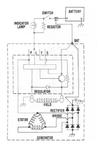
instead of the ignition's coil circuit? An alternator contains two coils, the
moving field coil on the rotor and the fixed stator coil in the alternator
housing. Some alternators have internal regulators while others have
external regulators. To accomodate all the different alt possibilities,
maybe FR is speaking generically about interrupting the field coil side
of the charging circuit?
On a CS130 ACDelco alternator in an '89 C4, the 'Batt' terminal stud
takes a heavy gauge wire and the 'L' terminal takes a small gauge
wire. This small gauge wire from the 'L' goes to the indicator light
and serves to activate/deactivate the field circuit in the alternator
which in turn controls current output from the circuit of the stator.
Compliments of
Service Manual - Delco-Remy CS-130 and CS121 Type Alternator
Years Used: 1986-1996
Amperages: CS-130/85-105 amps
CS-121/61-74 amps
The CS-121 and CS-130 may be used with only two wires connected to
the alternator. The output wire to the battery positive, and an "L"
terminal wire connected to the charge indicator bulb, or to the
resistor, or to both.
The charge indicator works in much the same way as on other charging
systems-the indicator lights when the switch is closed, and then goes
out when the engine is running. If the charge indicator is on with the
engine running a charging system defect is indicated.
The regulator limits the system voltage by controlling the rotor field
current. Unlike other regulators, this regulator switches the field
current on and off at a fixed frequency of about 400 cycles per
second. By varying the onoff time, the correct average field current for
proper system voltage control is obtained. At high speeds, the on-time
may be 10% and the offtime 90%. At low speeds with high electrical
loads the on-off time may be 90% and 10% respectively.
The relevance of all that to the business of installing a Bat/Alt shut-offYears Used: 1986-1996
Amperages: CS-130/85-105 amps
CS-121/61-74 amps
The CS-121 and CS-130 may be used with only two wires connected to
the alternator. The output wire to the battery positive, and an "L"
terminal wire connected to the charge indicator bulb, or to the
resistor, or to both.
The charge indicator works in much the same way as on other charging
systems-the indicator lights when the switch is closed, and then goes
out when the engine is running. If the charge indicator is on with the
engine running a charging system defect is indicated.
The regulator limits the system voltage by controlling the rotor field
current. Unlike other regulators, this regulator switches the field
current on and off at a fixed frequency of about 400 cycles per
second. By varying the onoff time, the correct average field current for
proper system voltage control is obtained. At high speeds, the on-time
may be 10% and the offtime 90%. At low speeds with high electrical
loads the on-off time may be 90% and 10% respectively.
is that it would appear that the small terminals should make/break the
circuit from 'L' to the charge indicator light.
However, IIRC, I wired the non-EFI car in a different fashion using
a relay and a Maxi-Fuse. If so, then I appear to have done that the
hard way. I'll need to refresh my memory and post later.
Meanwhile, maybe someone else can comment.
.
06-08-2008, 12:15 AM
#7
Team Owner


Member Since: Mar 2001
Location: Cincinnati, Oh USA
Posts: 53,932
Likes: 0
Received 26 Likes
on
23 Posts

There are a number of ways to wire a switch for emergency engine shutdown. If the switch has one pole (two contacts), the switch should be wired to shut off 12 volts to the ignition coil (or the ign module). One switch contact gets the 12v wire to the coil (or ign module), the other switch contact you connect a wire to and connect it to where the 12v coil or ign module wire went. Of course, the switch must be on in order to start and run the engine.
06-08-2008, 01:18 AM
#8
Le Mans Master
jfb, thanks for joining in.
Master shut-off switches are principally intended to cut battery power.
Many of them have just two heavy posts (single pole, as you point out)
for the (+) cable from the battery.
My understanding is that the 4-post (2-pole) switches are used to add
protection for the alternator (as well as eliminate the possibility of the
alternator continuing to provide power for the ignition) in the event that
battery power needs to be cut while the engine (& alternator) are turning.
In such a situation, apparently the alternator is damaged if the charging
circuit is disconnected from the battery while there is current output
from the stator.
If this understanding is correct, then would one workable approach be
to splice the small terminals of the Shut-Off switch into the circuit from
the 'L' terminal to the indicator light? Are there some other approaches
to consider?
.
06-08-2008, 08:31 AM
#9
Melting Slicks
Thread Starter
Gents this is all very helpful although not there yet. I have the top model in Salom's email and JFB I could just try the pink/blk on the ign module and see if that works. Also this LT4 is in a 64 Corvette Grand Sport but retained the standard engine wiring harness
Last edited by vstol; 06-12-2008 at 07:02 AM.
06-08-2008, 10:01 AM
#10
Burning Brakes

kinda simple for me...... i ran the battery cable and made a new hot wire from altenator(big wire bolted to the post) to the positive post on the switch and the cable from the cars starter and altenator to the negg side works great no isues so far!!
06-08-2008, 11:51 AM
#11
There are a number of ways to wire a switch for emergency engine shutdown. If the switch has one pole (two contacts), the switch should be wired to shut off 12 volts to the ignition coil (or the ign module). One switch contact gets the 12v wire to the coil (or ign module), the other switch contact you connect a wire to and connect it to where the 12v coil or ign module wire went. Of course, the switch must be on in order to start and run the engine.
You're correct on all this. But, wiring a cutoff switch this way will not pass technical inspection on a race car.
06-08-2008, 12:30 PM
#12
jfb, thanks for joining in.
Master shut-off switches are principally intended to cut battery power.
Many of them have just two heavy posts (single pole, as you point out)
for the (+) cable from the battery.
My understanding is that the 4-post (2-pole) switches are used to add
protection for the alternator (as well as eliminate the possibility of the
alternator continuing to provide power for the ignition) in the event that
battery power needs to be cut while the engine (& alternator) are turning.
In such a situation, apparently the alternator is damaged if the charging
circuit is disconnected from the battery while there is current output
from the stator.
If this understanding is correct, then would one workable approach be
to splice the small terminals of the Shut-Off switch into the circuit from
the 'L' terminal to the indicator light? Are there some other approaches
to consider?
.
Master shut-off switches are principally intended to cut battery power.
Many of them have just two heavy posts (single pole, as you point out)
for the (+) cable from the battery.
My understanding is that the 4-post (2-pole) switches are used to add
protection for the alternator (as well as eliminate the possibility of the
alternator continuing to provide power for the ignition) in the event that
battery power needs to be cut while the engine (& alternator) are turning.
In such a situation, apparently the alternator is damaged if the charging
circuit is disconnected from the battery while there is current output
from the stator.
If this understanding is correct, then would one workable approach be
to splice the small terminals of the Shut-Off switch into the circuit from
the 'L' terminal to the indicator light? Are there some other approaches
to consider?
.
http://www.pegasusautoracing.com/Images/L/4430-inst.jpg
Technical inspection requirements (at least for SCCA) are that the master switch must be installed on either battery cable and will cut all electrical circuits except the onboard fire extinguisher.
This FR switch is damn expensive at $83. The high quality switch from Pegasus is $54 and a Longacre is $30.
06-08-2008, 01:43 PM
#14
Team Owner
Member Since: Mar 2001
Location: Cincinnati, Oh USA
Posts: 53,932
Likes: 0
Received 26 Likes
on
23 Posts
The shutoff switches that disconnect the battery, also have a smaller current switch that also disconnects the alternator because the alternator can supply current to the engine systems with the battery disconnected. Disconnecting both the battery and the alternator output will completely shut of 12v to operate the engine and the engine will die (unless it has a magneto spark system).
If tech inspect won't pass a car with only one switch contact disconnecting the spark coil, then you need to find out what they require for emergency cutoff and comply. I suspect they want redundancy, more than one circuit shutting off electricity to the engine systems.
If tech inspect won't pass a car with only one switch contact disconnecting the spark coil, then you need to find out what they require for emergency cutoff and comply. I suspect they want redundancy, more than one circuit shutting off electricity to the engine systems.
06-09-2008, 01:04 PM
#16
Le Mans Master
The schematic Bill Hetzel provided for the #4430 Pegasus switch may
be the clue needed to help vstol with the Flaming River switch.
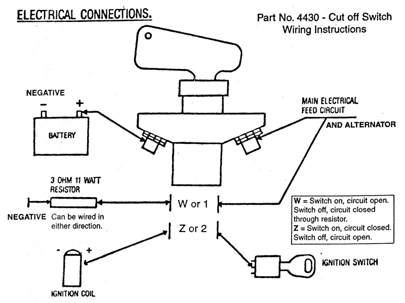
The 4430 appears to be a six post (3-pole) unit intended to control
the ign, along with the battery and alternator circuits.
When the switch is 'ON', the
Reexamination of the schematic for vstol's Flaming River switch shows
it also appears to be a six post (3-pole) unit.
Here is a revised schematic to illustrate the 'ON' position (as I imagine it
to be) beside the 'OFF' position.
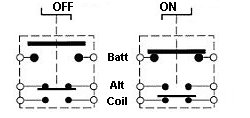
vstol. If you have a digital multi-meter or some other way of testing
continuity, you can test to determine whether your Flaming River
switch works in the manner suggested in the schematic. If it does,
then this indicates that the power conductor for your coil should pass
through the third set of contacts (OPEN when switch is OFF, CLOSED
when switch is ON.)
.
be the clue needed to help vstol with the Flaming River switch.
The 4430 appears to be a six post (3-pole) unit intended to control
the ign, along with the battery and alternator circuits.
When the switch is 'ON', the
- Batt Alt circuit is CLOSED (threaded lugs)
- Alt circuit is OPEN ('W or 1' spade terminals)
- Ign circuit is CLOSED ('Z or 2' spade terminals)
Reexamination of the schematic for vstol's Flaming River switch shows
it also appears to be a six post (3-pole) unit.
Here is a revised schematic to illustrate the 'ON' position (as I imagine it
to be) beside the 'OFF' position.
vstol. If you have a digital multi-meter or some other way of testing
continuity, you can test to determine whether your Flaming River
switch works in the manner suggested in the schematic. If it does,
then this indicates that the power conductor for your coil should pass
through the third set of contacts (OPEN when switch is OFF, CLOSED
when switch is ON.)
.
06-09-2008, 02:15 PM
#17
Le Mans Master
 06-09-2008, 03:46 PM
#18
Le Mans Master
Originally Posted by Slalom4me
If this understanding is correct, then would one workable approach be
to splice the small terminals of the Shut-Off switch into the circuit from
the 'L' terminal to the indicator light?
.
to splice the small terminals of the Shut-Off switch into the circuit from
the 'L' terminal to the indicator light?
.
say that the switch grounds the field terminal thru a resister. In your
GM diagram, it looks like the field is connected to the "Batt" terminal
and that is where I see the wires from the small terminals connected.
.
Bill Hetzel, interrupting the field looks like it would require surgery within
the alt case. OTOH, according to available info about the Delco alternator,
the 'L' circuit is a necessary external connection and appears to be used
to control charging.
"Most descriptions say that the switch grounds the field terminal thru
a resistor..."
Is it possible that the sources are speaking about a resistor that complimentsa resistor..."
the charge indicator lamp between the alternator's 'L' terminal and the
ign switch? IMO, this resistor is a back-up 'load' in the circuit to provide
fail-safe operation in the event that the bulb for the charge indicator
lamp burns out.
References for these conclusions are:
Exerpt from Helms '89 FSM (Section 6D3 - Charging System)
Operating Principals
"This generator uses at least two wire connections and a ground
path through the mounting bracket for operation. The battery positive
('Bat') terminal MUST* be connected to a battery during operation.
The second required connection is through the indicator light or suitable
external resistor to the 'L' terminal of the regulator, which serves to turn
the unit 'ON' at start-up."
(* - FSM's emphasis)
Generator Bench Check
Use a resistor of any value between 35 ohm, 5 watt, and 500 ohm.
1/2 watt between battery and "L" terminal.
Exerpt from Service Manual - Delco-Remy CS-130 and CS121 Type Alternator"This generator uses at least two wire connections and a ground
path through the mounting bracket for operation. The battery positive
('Bat') terminal MUST* be connected to a battery during operation.
The second required connection is through the indicator light or suitable
external resistor to the 'L' terminal of the regulator, which serves to turn
the unit 'ON' at start-up."
(* - FSM's emphasis)
Generator Bench Check
Use a resistor of any value between 35 ohm, 5 watt, and 500 ohm.
1/2 watt between battery and "L" terminal.
Years Used: 1986-1996
Amperages: CS-130/85-105 amps
CS-121/61-74 amps
The use of the "P", "F", and "S" terminals is optional.
.
Amperages: CS-130/85-105 amps
CS-121/61-74 amps
The use of the "P", "F", and "S" terminals is optional.
- The "P" terminal is connected to the stator, and may be
connected externally to a tachometer or other device. - The "F" terminal is connected internally to field positive, and
may be used as a fault indicator. - The "S" terminal may be connected externally to a voltage,
such as battery voltage, to sense the voltage to be controlled.
06-09-2008, 09:13 PM
#19
Melting Slicks
Thread Starter
Salom seat you the PDF to post. Will follow up on how the alt looks but I think its just a two wire exit. I am thinking the wire from the alt to the coil is where I need to grab it and use a 6amp 100 watt diode. Still working it from this end thanks for all your help.
06-09-2008, 10:14 PM
#20
Le Mans Master
vstol, judging from the contents of the .pdf file, the Flaming River
switch shares its circuitry layout with the Pegasus switch - the
diagrams show the same hook-ups.
Pegasus switch
Here is the clip of the schematic in the document
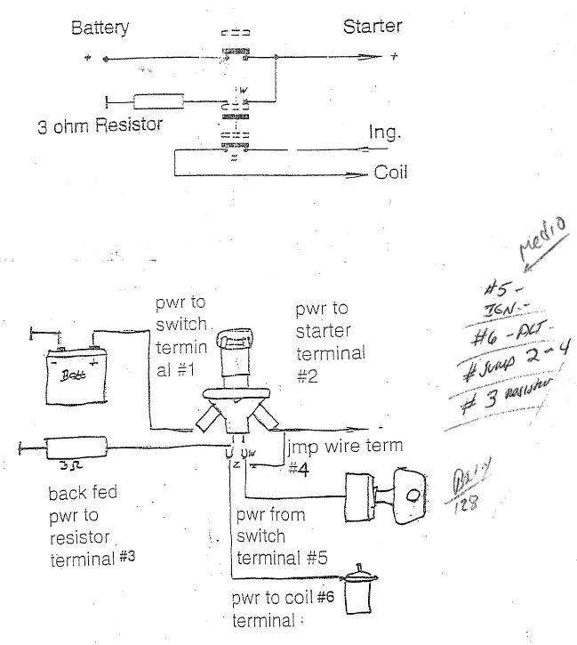 Notice that both schematics show the Ign switch & coil on the bottom
pair of contacts. There are some hand-written notes in the left margin
that state:
the following image
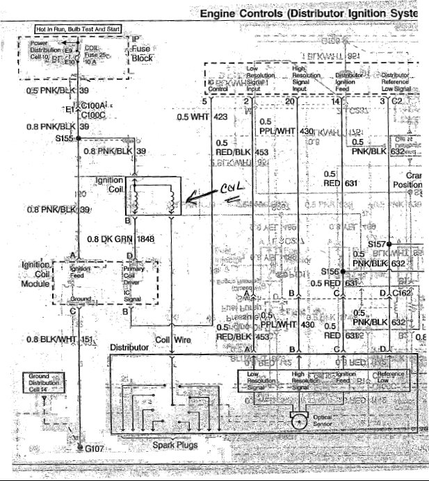
Here is a segment of the Engine Control diagram from the pdf. Some
image cleaning was done to the left side to remove 'noise'. (It is difficult
to be sure that only noise was removed, so refer to the pdf if in doubt.)
The coil appears to have 0.8 PNK/BLK and 0.8 DK GRN conductors, along
with the high tension wire to the distributor. (0.8 refers to the Metric
gauge of the wire, 0.8 is equivalent to 18 AWG.)
Are either of these conductors the ones you have already tried? If so, which
of the terminals did you use on the FR switch?
 .
.
switch shares its circuitry layout with the Pegasus switch - the
diagrams show the same hook-ups.
Pegasus switch
pair of contacts. There are some hand-written notes in the left margin
that state:
- #5 IGN
- #6 ALT
However, this seems to contradict the printed schematics above and - #6 ALT
the following image
Originally Posted by vstol
I have tried both the green wire (Flaming River suggests/guess)
and it will not start. I have tried the pink and nothing happens.
The green and pink are the coil wires.
I could just try the pink/blk on the ign module and see if that works.
and it will not start. I have tried the pink and nothing happens.
The green and pink are the coil wires.
I could just try the pink/blk on the ign module and see if that works.
image cleaning was done to the left side to remove 'noise'. (It is difficult
to be sure that only noise was removed, so refer to the pdf if in doubt.)
The coil appears to have 0.8 PNK/BLK and 0.8 DK GRN conductors, along
with the high tension wire to the distributor. (0.8 refers to the Metric
gauge of the wire, 0.8 is equivalent to 18 AWG.)
Are either of these conductors the ones you have already tried? If so, which
of the terminals did you use on the FR switch?