
Baffled Valve Covers for a C4
 05-12-2009, 05:49 PM
#1
Le Mans Master

Thread Starter
Member Since: Oct 2007
Location: Akron Ohio
Posts: 8,868
Received 1,753 Likes
on
941 Posts
2023 C5 of the Year Finalist - Modified
2022 C5 of the Year Finalist - Modified
St. Jude Donor '09-'10-'11

I am getting oil in the intake on my street driven C4 with the stock PCV setup. Under hard left corners the throttle body sucks up some oil through the pass. side valve cover vent. I tried using a filter breather and was fine for a while but oil started coming out the breather and onto the header (not good  ). I went back to the stock setup for now but was wondering if anyone knows of some good baffled valve covers and breathers to replace the stock setup, and keep the oil inside the engine?? I guess I could use a catch can but if there is a setup that will bolt on I would like to try it. I was thinking of using these. It says they are baffled but I dont know how well they work.
). I went back to the stock setup for now but was wondering if anyone knows of some good baffled valve covers and breathers to replace the stock setup, and keep the oil inside the engine?? I guess I could use a catch can but if there is a setup that will bolt on I would like to try it. I was thinking of using these. It says they are baffled but I dont know how well they work.
 05-12-2009, 07:04 PM
#2
Le Mans Master

I believe I have a pair of the Proform #141-131 in a box.
I can check and take a photo later today. This would give you
an indication of what kind of baffling Proform provides. I have
not used them so I can not give a firsthand report about their
performance. IIRC, they are baffled similarly to the OEM covers.
.
I can check and take a photo later today. This would give you
an indication of what kind of baffling Proform provides. I have
not used them so I can not give a firsthand report about their
performance. IIRC, they are baffled similarly to the OEM covers.
.
05-12-2009, 07:09 PM
#3
Le Mans Master
Thread Starter
Member Since: Oct 2007
Location: Akron Ohio
Posts: 8,868
Received 1,753 Likes
on
941 Posts
2023 C5 of the Year Finalist - Modified
2022 C5 of the Year Finalist - Modified
St. Jude Donor '09-'10-'11
I believe I have a pair of the Proform #141-131 in a box.
I can check and take a photo later today. This would give you
an indication of what kind of baffling Proform provides. I have
not used them so I can not give a firsthand report about their
performance. IIRC, they are baffled similarly to the OEM covers.
.
I can check and take a photo later today. This would give you
an indication of what kind of baffling Proform provides. I have
not used them so I can not give a firsthand report about their
performance. IIRC, they are baffled similarly to the OEM covers.
.
If the baffling is similar would I still have an issue with spilling oil? Or would them being tall instead of stock height help also?
Edit:
I dont know why my email always shows up with a hyperlink, even when I turn it off, but there is an underscore between the Kubs and the 63.
05-13-2009, 10:09 AM
#4
Le Mans Master
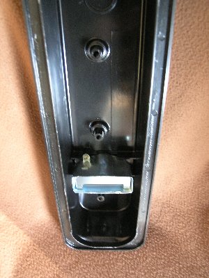
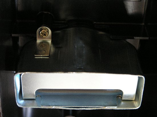
The Proform #141-131 valve cover has one OEM-like sheet metal baffle
in each casting. The cover height is roughly 2-3/8" from the gasket
face to the top of the interior. I do not have the dimensions for a
stock cover, my vote is there is not enough difference to impact
oil handling.
The baffle is roughly 2-1/8" tall and contains at least three stamped
separators. These create an alternating 'staircase' for vapours to
negotiate.
 .
. 
.
in each casting. The cover height is roughly 2-3/8" from the gasket
face to the top of the interior. I do not have the dimensions for a
stock cover, my vote is there is not enough difference to impact
oil handling.
The baffle is roughly 2-1/8" tall and contains at least three stamped
separators. These create an alternating 'staircase' for vapours to
negotiate.
.
05-13-2009, 11:26 AM
#5
Le Mans Master
Originally Posted by Kubs
I am getting oil in the intake on my street driven C4 with the
stock PCV setup. Under hard left corners the throttle body
sucks up some oil through the pass. side valve cover vent.
stock PCV setup. Under hard left corners the throttle body
sucks up some oil through the pass. side valve cover vent.
fitting in the rear of the passenger side valve cover. An
extraction hose draws air from the PCV in the front of the
driver's side cover into the intake base.
Flow from the pass side back to the TB is a reversal of normal
travel.
Is the PCV working freely and sealing properly? Is there manifold
vacuum present in the hose between the PCV and intake base?
Any indication of excessive blow-by due to engine wear?
.
05-13-2009, 11:53 AM
#6
Team Owner

Member Since: Mar 2001
Location: Boston, Dallas, Detroit, SoCal, back to Boston MA
Posts: 30,607
Received 239 Likes
on
167 Posts

You can ring a catch can to the system.
I know we've got oil stackup issues with the heads in turns.
(PS now you now why I'm going through the trouble of putting a dry sump in)
I know we've got oil stackup issues with the heads in turns.
(PS now you now why I'm going through the trouble of putting a dry sump in)
05-13-2009, 02:29 PM
#7
Race Director

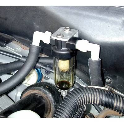
A catch can is really easy to plumb:

I used that for testing and it did catch some oil. Not as much as I would have thought though. I'd like to get a decent one and install that one of these days.
I used that for testing and it did catch some oil. Not as much as I would have thought though. I'd like to get a decent one and install that one of these days.
05-13-2009, 04:09 PM
#8
Le Mans Master
Thread Starter
Member Since: Oct 2007
Location: Akron Ohio
Posts: 8,868
Received 1,753 Likes
on
941 Posts
2023 C5 of the Year Finalist - Modified
2022 C5 of the Year Finalist - Modified
St. Jude Donor '09-'10-'11
On a stock L98, an inlet hose supplies air from the TB to a
fitting in the rear of the passenger side valve cover. An
extraction hose draws air from the PCV in the front of the
driver's side cover into the intake base.
Flow from the pass side back to the TB is a reversal of normal
travel.
Is the PCV working freely and sealing properly? Is there manifold
vacuum present in the hose between the PCV and intake base?
Any indication of excessive blow-by due to engine wear?
.
Do you have any more pictures of this? I cant quite make out how you are routing the hoses. Is that your catch can next to the booster? It looks kinda small. Were all the peices purchased or did you make them?
05-13-2009, 08:52 PM
#9
Race Director
Yes, I just cut some hose to fit. Make sure it's reinforced type hose that doesn't close from the suction. There are tons of catch cans out there from a simple can you can make to high dollar coalescing type filters.
05-13-2009, 09:20 PM
#10
Le Mans Master
Thread Starter
Member Since: Oct 2007
Location: Akron Ohio
Posts: 8,868
Received 1,753 Likes
on
941 Posts
2023 C5 of the Year Finalist - Modified
2022 C5 of the Year Finalist - Modified
St. Jude Donor '09-'10-'11
Where did you get yours? On summit they are all labled as coolant catch cans..
05-13-2009, 10:31 PM
#11
Le Mans Master
My vote is that Aardwolf's configuration (c-can on the outbound
hose between the PCV and intake base) may not make much of
an improvement in the symptoms Kubs describes (oil in entering
intake on hard left cornering.)
My reasoning is this. Hard left cornering contributes to oil stacking
up in the rear of the passenger side valve cover.
Although the hose to the fitting at the back of the cover is
supposed to flow from the TB to the cover (due to vacuum in
the crankcase from the hose on the driver's side), above normal
blow-by may be reversing flow, resulting in oil moving up to the
TB and then into the intake.
In such a case, mounting a catch can in the hose path from the
TB to the pass side cover may prove more satisfactory.
A cylinder leak-down test (different from a compression test) will
provide a quantifiable measure of how much blow-by is occuring.
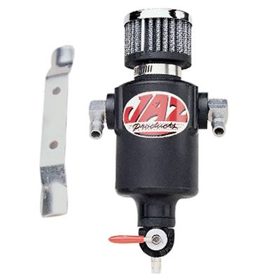
As for locating parts, search using terms like separator tank and
breather tank. You can chose a purpose-built aluminum or
plastic unit or you could adapt a common part used for
compressed air lines.
Examples
hose between the PCV and intake base) may not make much of
an improvement in the symptoms Kubs describes (oil in entering
intake on hard left cornering.)
My reasoning is this. Hard left cornering contributes to oil stacking
up in the rear of the passenger side valve cover.
Although the hose to the fitting at the back of the cover is
supposed to flow from the TB to the cover (due to vacuum in
the crankcase from the hose on the driver's side), above normal
blow-by may be reversing flow, resulting in oil moving up to the
TB and then into the intake.
In such a case, mounting a catch can in the hose path from the
TB to the pass side cover may prove more satisfactory.
A cylinder leak-down test (different from a compression test) will
provide a quantifiable measure of how much blow-by is occuring.
As for locating parts, search using terms like separator tank and
breather tank. You can chose a purpose-built aluminum or
plastic unit or you could adapt a common part used for
compressed air lines.
Examples
Steeda 555-3710 (An inline pneumatic oil separator adapted for automotive use)
Moroso 85471
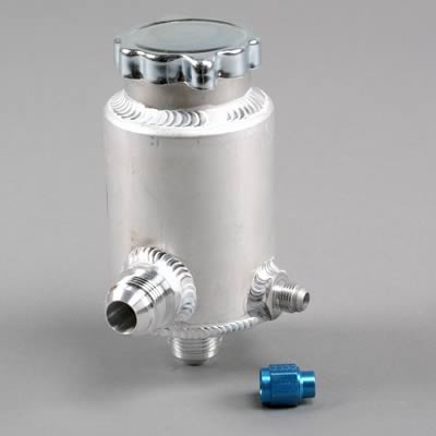
Jaz 605-325-01
.
Moroso 85471
Jaz 605-325-01
05-13-2009, 10:46 PM
#12
Le Mans Master
Thread Starter
Member Since: Oct 2007
Location: Akron Ohio
Posts: 8,868
Received 1,753 Likes
on
941 Posts
2023 C5 of the Year Finalist - Modified
2022 C5 of the Year Finalist - Modified
St. Jude Donor '09-'10-'11
Hoe does one perform a leak-down test and what kind of results should I look for?
05-13-2009, 10:50 PM
#13
Le Mans Master
EG@EnglandGreen posted about the Elite Catch Can several years
ago. It is still the nicest one I recall seeing.
.
ago. It is still the nicest one I recall seeing.
.
 05-13-2009, 11:12 PM
#14
Le Mans Master
Longacre and others provide instructions as follows
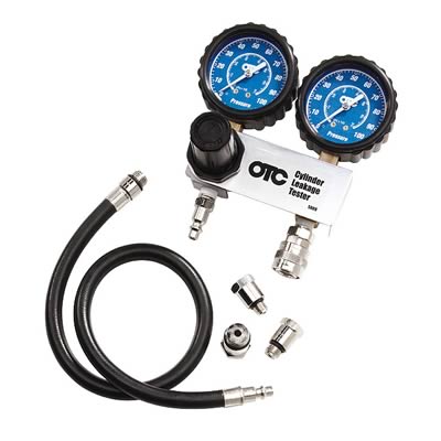
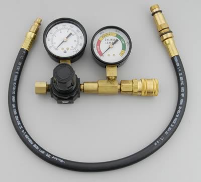

They recommend setting the piston at BDC to prevent any chance
of air pressure rotating the crank.
My vote is that better test results are obtained if a device to hold
the flywheel is made or bought so that measurements can be made
with the piston/rings at TDC where the greatest cylinder wear typically
occurs. (This method also does away with Longacre's step of
loosening/removing the rocker arms.)
.
05-14-2009, 08:49 AM
#15
Race Director
Yeah just an example to use on that side. Speaking of the passenger side, I didn't have exactly the same problem but I did find that oil leaked out of the filler cap at my last event. It's screwed down tight but the threads must not seal to well. It wasn't that much that it drained on the header but I could see the liquid trail.
05-14-2009, 11:12 AM
#16
Le Mans Master
Thread Starter
Member Since: Oct 2007
Location: Akron Ohio
Posts: 8,868
Received 1,753 Likes
on
941 Posts
2023 C5 of the Year Finalist - Modified
2022 C5 of the Year Finalist - Modified
St. Jude Donor '09-'10-'11
I noticed that too so I started using RTV around the cap and havnt had an issue since. When I need to add oil the perfect ring of RTV stays on the valve cover.
Does anyone sell the rubber gromets that go into the valve covers for the PCV system? Mine are kinda loose and worn out.
Does anyone sell the rubber gromets that go into the valve covers for the PCV system? Mine are kinda loose and worn out.
05-14-2009, 11:15 AM
#17
Le Mans Master
A consideration if someone is looking at adapting an oil trap from a
pneumatic application. My vote is that for the passenger side hose,
the separator should be installed 'backward'.
The ports on these components are typically marked with arrows
or 'inlet/outlet' to indicate direction of flow. For a separator, the
intended flow path is into the perimeter where oil/water can settle
in the trap while the air passes up into the filter in the center and
then on out.
However, while the air movement on the pass side is from the TB
to the valve cover, more importantly, the oil movement is in the
opposite direction. If the separator is installed with the arrows
from the TB to the v-cover, my vote is that oil moving backward
will foul the filter in the separator. If the arrows point from the
v-cover to the TB, oil will settle in the trap while air will flow
'backwards' unimpeded from the TB to the v-cover.
The flow of air and oil are both in the same direction on the driver's
side. Install the arrows to point from the PCV to the intake base.
ARO, Parker and others make such items.
.
05-14-2009, 11:20 AM
#18
Le Mans Master
Moroso has some grommets that incorporate a bit of a separator
feature for covers with no baffles. I do not know off hand whether
these will co-exist with baffles.
.
05-14-2009, 11:22 AM
#19
Le Mans Master
Thread Starter
Member Since: Oct 2007
Location: Akron Ohio
Posts: 8,868
Received 1,753 Likes
on
941 Posts
2023 C5 of the Year Finalist - Modified
2022 C5 of the Year Finalist - Modified
St. Jude Donor '09-'10-'11
A consideration if someone is looking at adapting an oil trap from a
pneumatic application. My vote is that for the passenger side hose,
the separator should be installed 'backward'.
The ports on these components are typically marked with arrows
or 'inlet/outlet' to indicate direction of flow. For a separator, the
intended flow path is into the perimeter where oil/water can settle
in the trap while the air passes up into the filter in the center and
then on out.
However, while the air movement on the pass side is from the TB
to the valve cover, more importantly, the oil movement is in the
opposite direction. If the separator is installed with the arrows
from the TB to the v-cover, my vote is that oil moving backward
will foul the filter in the separator. If the arrows point from the
v-cover to the TB, oil will settle in the trap while air will flow
'backwards' unimpeded from the TB to the v-cover.
The flow of air and oil are both in the same direction on the driver's
side. Install the arrows to point from the PCV to the intake base.
ARO, Parker and others make such items.
.
pneumatic application. My vote is that for the passenger side hose,
the separator should be installed 'backward'.
The ports on these components are typically marked with arrows
or 'inlet/outlet' to indicate direction of flow. For a separator, the
intended flow path is into the perimeter where oil/water can settle
in the trap while the air passes up into the filter in the center and
then on out.
However, while the air movement on the pass side is from the TB
to the valve cover, more importantly, the oil movement is in the
opposite direction. If the separator is installed with the arrows
from the TB to the v-cover, my vote is that oil moving backward
will foul the filter in the separator. If the arrows point from the
v-cover to the TB, oil will settle in the trap while air will flow
'backwards' unimpeded from the TB to the v-cover.
The flow of air and oil are both in the same direction on the driver's
side. Install the arrows to point from the PCV to the intake base.
ARO, Parker and others make such items.
.
05-14-2009, 11:27 AM
#20
Le Mans Master
MOR-97340 Moroso Breather/Filler Cap Grommets
Valve Cover Grommets, Breather, 1.22 in. Outside Diameter, 1 in. Inside Diameter, Pair
MOR-68772 Moroso PCV Grommets with Integral Baffles
Valve Cover Grommet, PCV, 1.22 in. Outside Diameter, 1 in. Inside Diameter, Each
MOR-68775 Moroso Breather Grommets with Integral Baffles
Valve Cover Grommets, Breather, 1.22 in. Outside Diameter, 1 in. Inside Diameter, Pair
Valve Cover Grommets, Breather, 1.22 in. Outside Diameter, 1 in. Inside Diameter, Pair
MOR-68772 Moroso PCV Grommets with Integral Baffles
Valve Cover Grommet, PCV, 1.22 in. Outside Diameter, 1 in. Inside Diameter, Each
MOR-68775 Moroso Breather Grommets with Integral Baffles
Valve Cover Grommets, Breather, 1.22 in. Outside Diameter, 1 in. Inside Diameter, Pair