When you click on links to various merchants on this site and make a purchase, this can result in this site earning a commission. Affiliate programs and affiliations include, but are not limited to, the eBay Partner Network.
Chasing your Z06 is like trying to chase a Daytona prototype with a civic. I had to utilize all the track surface tracking out from side to side just to keep pace with you and I had tears in my eyes watching your car following the track like it's on rail. All that nice aero package really helped and your strong Katech engine is definitely a plus
So Anthony, you are absolutely right about fog light opening - it reduce air flow to the brake cooling duct compare with stock setup! I stay up all night before track event to fashion the fog light air duct thinking it will add more air flow - boy was I wrong. Here is my wind speed test results
I use my leaf blower to generate the wind and Kestrel wind speed meter for measurement. The Lowes' leaf blower was strong enough to generate 126 mph wind speed at the nozzle!
Directing the air flow above and below splitter and through the opening on the front apron and fog light opening and measure maximum wind speed with stock vs "modified fog light air vent" setups
Maximum wind speed exiting the brake cooling duct with stock setup was through the apron opening above the splitter at 48.7 mph
Below the splitter maximum wind generated was 32.2 mph
Now the modified fog light opening setup. When I aim the leaf blower right at the fog light air vent it generated merely 27.7 mph which is similar from below the splitter with this setup. .... all that hard work for nothing
The Maximum wind speed for the fog light air vent setup was generated from the front apron opening above the splitter at 34.4 mph which is 14.3 mph slower than stock setup.
Wind speed diminish with distance. When I move 3 feet away from the leaf blower (which is about the distance for wind to travel from front of bumper to brake duct opening in the wheel well) the maximum wind speed was about 30 mph. I think as air travel front front apron opening under the car into the brake duct it may experience some sort of compression effect that's why wind speed exiting brake duct opening was higher compare with fog light opening
Because wind speed decrease with distance - by the time it reach the rotor from brake duct opening it would have diminished in strength so it's best to have spindle brake cooling duct direct as much air as possible to the rotor - esp a red hot CCM that's above 1000F. In grand scheme of things wind speed at 34 mph vs 47 mph from brake cooling duct 2 feet from the rotor may not have made much difference. Now this is with leaf blower generating 126 mph wind at the nozzle. Imagine coming to a slow tight turn going from 110+ mph to 30 mph and just when the rotor is at it's hottest you have least amount of wind to cool the rotor .... we need a smart electric cooling fan that sense speed difference under hard braking and generate 50+ mph wind at low vehicle speed to cool the rotor
So now it looks like stock setup it is with spindle air vent from LG and if that's not enough I will try to come up with something else - perhaps air vent directly behind the front apron opening
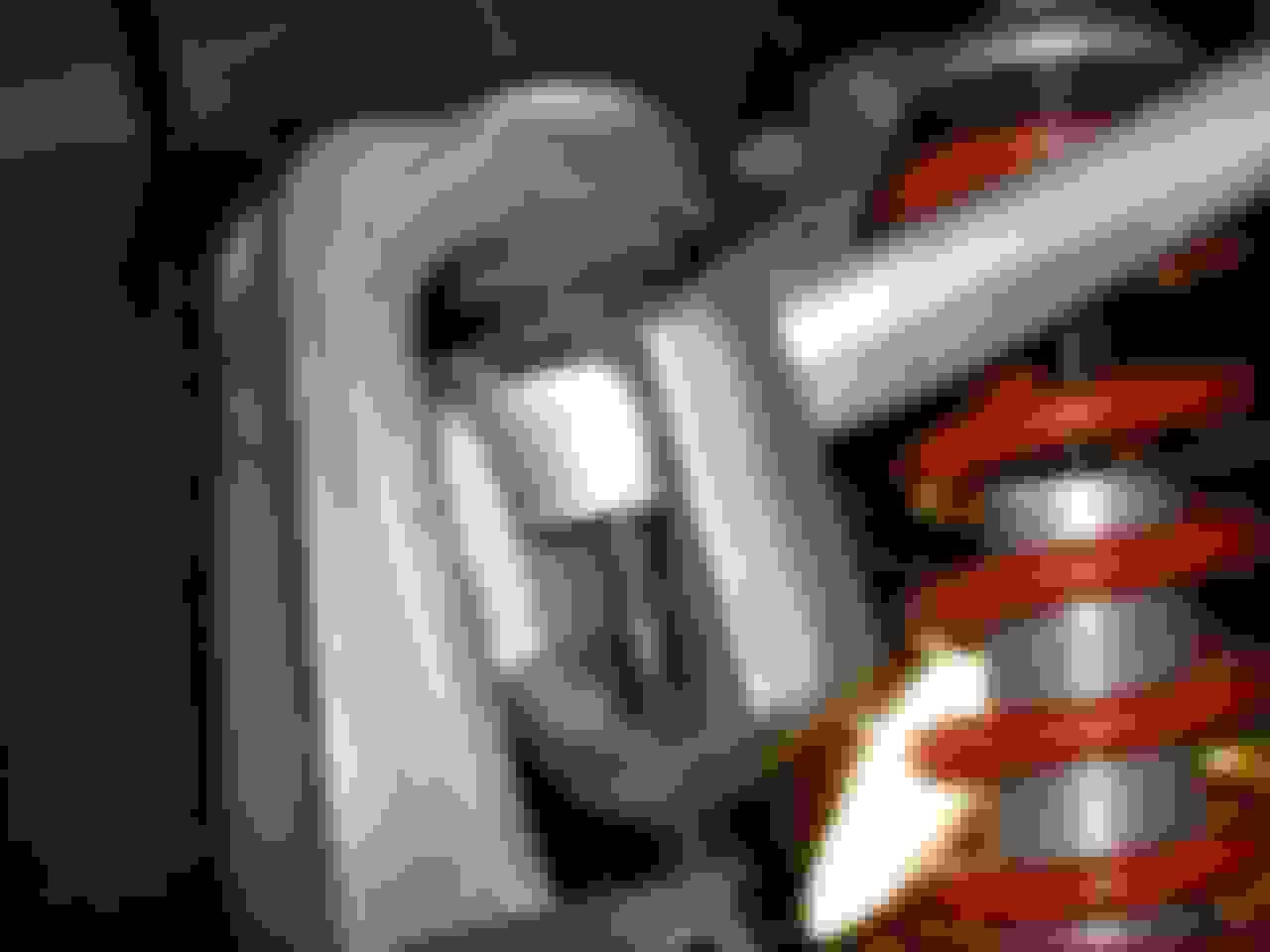
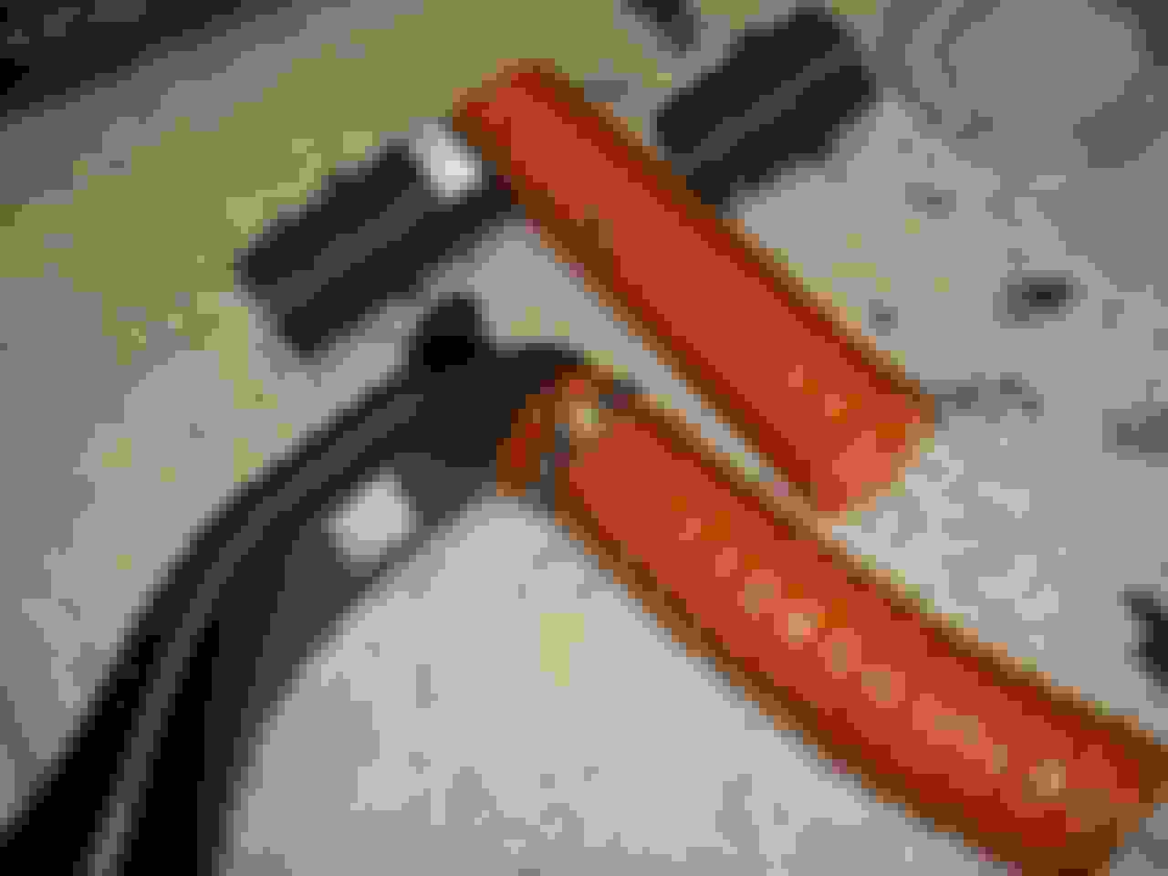
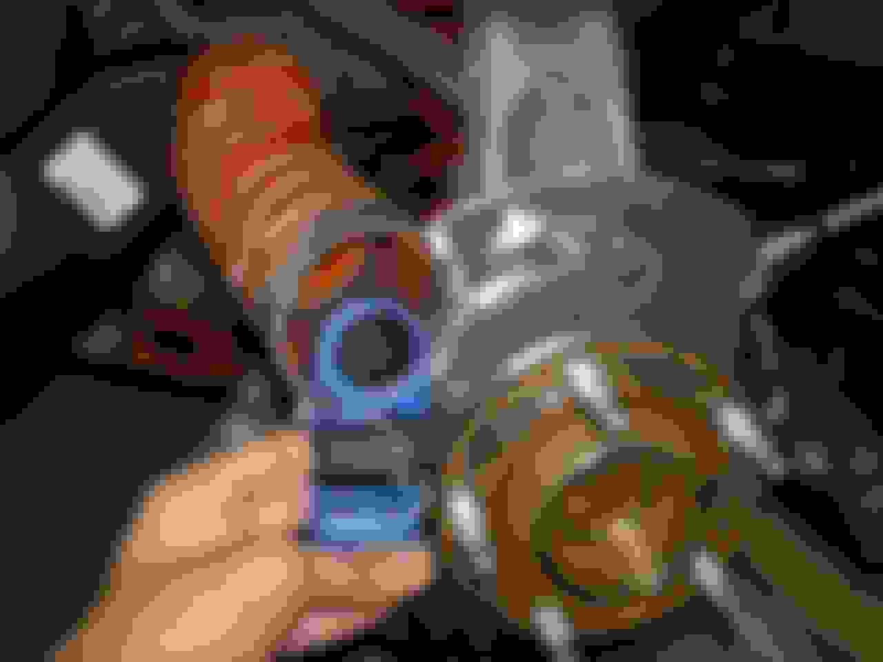
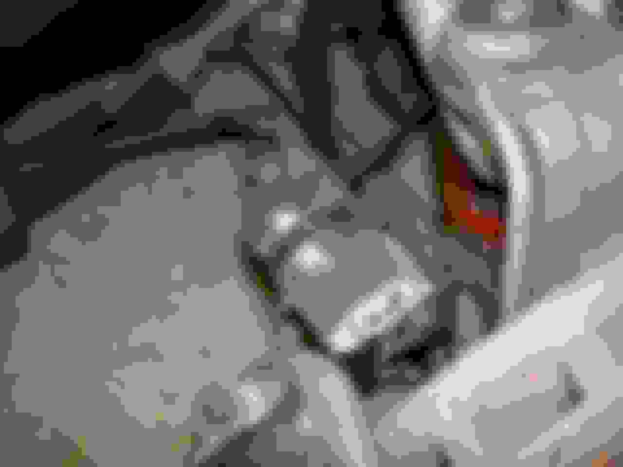
Last year I did something similar to what you did. I put some ducts in place of the fog lights and connected them to the stock ducts. I used aluminum tubing Y'd into the stock duct to make the air flow as smooth as possible. I didn't have the sharp turn you had going into the stock duct but I had a sharp turn where the air exited the fog light duct and I expect a lot of turbulence in the flexible tubing used to connect the fog light duct to the aluminum tubing. I didn't have a air speed meter but after several track events with miserable brake problems I used a leaf blower in front of the fog light and placed my hand at the end of the spindle duct. There wasn't a lot of air coming out.
Here are some pictures showing what I had:
Once the air entered the flexible duct it was almost a direct shot right into the stock duct just before the point where the duct narrowed.
A few months later I was having an aero discussion with one of the C7 Aero Engineers at Carlisle and we got into the air flow around the front bumper of both the C7 and C6. On both the fog lights are sort of in a dead air zone with little air pressure at speed. That probably meant when I was driving I was getting even less air flow than I felt with the leaf blower. I went back to an LG Duct stock replacement duct to get the 3 inch reinforced outlet and the Lambert Spindle ducts (with the rear outlet taped off with aluminumized duct tape.
By the way if anybody wants to try my ducts I still have them. They are yours for the cost of shipping.
There's a reason GM didn't put air ducts to the brakes from the fog light area for the C6 ZR1. They didn't use the wind tunnel testing just for downforce tests.... Give GM some credit for knowing what they were doing.
Last year I did something similar to what you did. I put some ducts in place of the fog lights and connected them to the stock ducts. I used aluminum tubing Y'd into the stock duct to make the air flow as smooth as possible. I didn't have the sharp turn you had going into the stock duct but I had a sharp turn where the air exited the fog light duct and I expect a lot of turbulence in the flexible tubing used to connect the fog light duct to the aluminum tubing. I didn't have a air speed meter but after several track events with miserable brake problems I used a leaf blower in front of the fog light and placed my hand at the end of the spindle duct. There wasn't a lot of air coming out.
Here are some pictures showing what I had:
Once the air entered the flexible duct it was almost a direct shot right into the stock duct just before the point where the duct narrowed.
A few months later I was having an aero discussion with one of the C7 Aero Engineers at Carlisle and we got into the air flow around the front bumper of both the C7 and C6. On both the fog lights are sort of in a dead air zone with little air pressure at speed. That probably meant when I was driving I was getting even less air flow than I felt with the leaf blower. I went back to an LG Duct stock replacement duct to get the 3 inch reinforced outlet and the Lambert Spindle ducts (with the rear outlet taped off with aluminumized duct tape.
By the way if anybody wants to try my ducts I still have them. They are yours for the cost of shipping.
Bill
Yes, saw saw you fog light opening mod and thanks for sharing your discussion with engineers at Carlisle. Apparently someone make an electric fan for added brake cooling but result was disappointing when tested on GTR: http://www.gtrheritage.com/topic/129...g-kit-results/
If you look into those a little further you will find that those fans are just marine fans used to vent the engine compartments. They use them to remove gasoline fumes and they are low cost but I think that they only move something like 20-30cfm.
If you look into those a little further you will find that those fans are just marine fans used to vent the engine compartments. They use them to remove gasoline fumes and they are low cost but I think that they only move something like 20-30cfm.
what we really need is one of your werks nitrous engine to power the fan and keep the brakes nice and chill
Werks - Didn't you have the Katech undertray with brake cooling ducts prior to the GT2 splitter? How did that do in terms of cooling? I'd think that would be a pretty good compromise between nothing and the GT2 without disturbing the balance of the car with additional front aero.
Got the LG spindle cooling setup and had a chance to install it. Take time to do the install right - some modification is needed. It's not a quick DIY so take your time to do it right
Here is the bad boy. LG has reinforced the spindle cooling duct with extra welds.
Remove the two brake caliper bolts with 21 mm socket. This is about the most labor intensive part. The bolts are coated with thread lock and it's like doing 100 lbs dead lift with every turn of the bolt
The thin metal sheet sandwiched between the wheel hub and spindle is where you will fit the LG spindle duct
Next you need to use control arm pulling tool to get access to the lower wheel hub bolt which is blocked by lower control arm bolt. I got the Pitman puller #27016 from Autozone. You can borrow it from them too if you don't want to buy one
Remove the control arm bolts - 18 mm upper arm and 21 mm lower arm. and fit the Pitman puller and gently pull the control arm lose.
You need a floor jack to raise the control arms higher and remove the upper control arm first then tilt the spindle away from car to get access to fit Pitman puller on lower control arm
Make sure the Pitman arm puller is seated properly on lower control arm stud as not to damage it - it's a tight fit
It's easier to loosen the upper two wheel hub bolts first before removing control arm bolts. Now lift the spindle up slightly and remove the lower wheel hub bolt which is a black bolt - different from the other two. You need a T55 torx socket to remove the bolts
Now carefully remove the wheel hub assembly - make sure to disconnect the wheel speed sensor. Clean the wheel hub and spindle before putting everything back
Stock sandwich plate next to LG spindle cooling duct
Test fit of LG spindle cooling duct shows that it block the upper caliper mount so it need slight trimming
Tighten the three wheel hub bolts to 96 ft lbs and install upper and lower control arms bolts. Both control arm bolts call for initial torque of 22 ft lbs then upper control arm need to be tighten another 120 degree turn and lower control arm bolt another 180 degree turn. I had a hard time getting the extra 180 degree turn for lower bolt and it require alot of elbow grease. You may need to use allen wrench to steady the stud when you make the first 22 ft lbs torque
Check the wheel speed sensor plug and carefully zip tie away so it does not come in contact with moving suspension parts
This is what it looks like installed
Now if you chose to use your stock brake cooling duct it need some modification to securely attach the flexible hose. The opening of the brake duct is very flimsy and much smaller than the flexible hose. After couple trial I decided to get a garden irritation hose adapter from Lowes (which can be found at the Motorsports section lol) and cut the ends off and attach at the brake duct opening with three small screws so it's wider and sturdy enough to clamp down the flexible hose. I also use a zip tie through the metal clamp to make sure it does not slide off
Now I have two different types of high temperature flexible hose - the orange one from LG and a black rubber corrugated hose. Which one is better for air flow? Let's find out.
The study was done with steady wind generated to left wheel well with leaf blower aiming the brake duct opening below the car
First the black rubber corrugated hose:
49.5 mph - steering wheel center
45.8 mph - steering wheel full lock to right (shortest flexible duct length)
46.3 mph - steering wheel full lock to left (longest flexible duct length)
Now the orange flexible hose
First the black rubber corrugated hose:
50.3 mph - steering wheel center
50.3 mph - steering wheel full lock to right (shortest flexible duct length)
44.6 mph - steering wheel full lock to left (longest flexible duct length)
Since most braking on the track are done with steering wheel at neutral - car pointing straight - I decided to use orange flexible hose since it produce slightly more wind speed
Orange hose
Now the spindle brake cooling duct is all done let's go for a rotor temperature test. With stock brake cooling set up my rotor brake temperature easily climb past 1000F after thirty 60-10 mph stop and rotor temp remain elevated past 600F for a long time during cool down. Now with the spindle cooling setup I noticed the max rotor temp at end of thirty 60-10 mph stop barely went over 800F and rotor temp drop dramatically faster to 300-400F range during cool down. Once I pick up speed on freeway 65-70 mph the rotor temp went all the way down to mid 200F! Wow, pretty impressed how well these brake spindle cooling duct work! Will have Thunderhill track rotor temp recording in couple days
IR temp sensor probe. Pretty impressed with these Omega industrial IR probe. They can take a beating and keep on working
LG spindle brake cooling setup
Max rotor temp of 801F displayed at right corner of dash at end of thirty 60-10 mph bedding procedure
Thanks for taking the time to share this with the rest of us. I have a couple of questions.
Originally Posted by mikymu
You are lucky if you don't have over heat issue. I use industrial type infrared pyrometer made by Omega and attach it on the spindle near caliper to take real time rotor temp - every single brake zone at Thunderhill exceed 1000F - yes, every single brake zone
Video below was from recent track test at Thunderhill 5 miles course. At end of video CCM brake over heat after two quick tap at Turn 7 west and send the brake into ICE mode where brake pedal became hard and I barely able to wrestle the car around the turn - in so doing upset the car and a small throttle input send the butt around.
Unfortunately the G-meter is covering the pyrometer readout in the video. Do you recall the rotor temp at the time of the spin? Does the pyrometer retain data over the recorded time period, or do you just have to read it and record manually?
You are back to running the CCM rotors. Are you testing some new pads, and if so, are they an improvement. I will be anxious to see if better pads and getting the temperature under control with spindle ducts will give you the control and modulation that has been missing.
what we really need is one of your werks nitrous engine to power the fan and keep the brakes nice and chill
Lol, it would be a pain having to start them up each time before you go out!
Originally Posted by phipp85
Werks - Didn't you have the Katech undertray with brake cooling ducts prior to the GT2 splitter? How did that do in terms of cooling? I'd think that would be a pretty good compromise between nothing and the GT2 without disturbing the balance of the car with additional front aero.
Yes I used to run the full Katech aero package and it works great. As I got faster though I started trying to improve the downforce of the car and that led me to add one of the ACP World Challenge wings to the car which as you can see in the video that mike posted (I'm the orange car in front at the start of the video) is a pretty big honking wing that makes a lot of downforce. To match front downforce with rear I had to go with a bigger front splitter and that is what led me to the LG Gt2 splitter, which is about 2-3" longer than the Katech one. In regards to the cooling the Katech set up is great and the air opening for the cooling duct is probably about 2x as big as on the stock splitter and they have built in carbon ducting too, so I had no overheating problems with that. The GT2 splitter has even larger air intake vents which are probably about 50% larger than what was on the Katech splitter, so it's getting even more air in. Now having said that the Katech part is a functional, show quality part. The GT2 splitter is a functional, race quality part. So if appearance is critical the GT2 splitter is no where as nicely finished, plus for street use it is quite big and extends pretty far out in front of the car, so curbs etc are a bit of a challenge.
Thanks. Yes, it's alot of work and had to take some Ibuprofen after everything is done
Originally Posted by Bad_AX
Mike,
Thanks for taking the time to share this with the rest of us. I have a couple of questions.
Unfortunately the G-meter is covering the pyrometer readout in the video. Do you recall the rotor temp at the time of the spin? Does the pyrometer retain data over the recorded time period, or do you just have to read it and record manually?
You are back to running the CCM rotors. Are you testing some new pads, and if so, are they an improvement. I will be anxious to see if better pads and getting the temperature under control with spindle ducts will give you the control and modulation that has been missing.
Glad to answer your questions
The IR pyrometer does not record temp data - it can, but you need to have a mini laptop in the car and I have not figure out how to hook it up to my Aims data recorder. I tried to record the temp reading on gopro but the frequency of the pyrometer digital display interfere with my gopro 30 frames per second setting so all you can see on the video is some gibberish numbers. I cover up the pyromter readings with G meter in the video because all that crazy numbers are distracting. I set up the pyrometer to flash when temp go beyond 950F and it's flashing at just about every brake zones including 7W where I spun. I took a screen shot at 7W just before I spun and you can see the faint 999F displayed on the pyromter shown below - which was the max temp for this unit
I adjust the gopro to 48 frames per second and it seems to record the pyromter reading well at recent rotor temp test run. Hope to capture some clear readouts at next track test in couple days
I am testing endless W007 front brake pads with OEM rear - same as Werks' set up. I am definitely applying too much brake pressure - not knowing if the car will slow down with CCM hence locking up the wheels all the time. Once I get more confident with CCM with better cooling I should be able to modulate the brakes better .... I hope
Originally Posted by Werks
Mike, awesome write up as usual!
Lol, it would be a pain having to start them up each time before you go out!
Yes I used to run the full Katech aero package and it works great. As I got faster though I started trying to improve the downforce of the car and that led me to add one of the ACP World Challenge wings to the car which as you can see in the video that mike posted (I'm the orange car in front at the start of the video) is a pretty big honking wing that makes a lot of downforce. To match front downforce with rear I had to go with a bigger front splitter and that is what led me to the LG Gt2 splitter, which is about 2-3" longer than the Katech one. In regards to the cooling the Katech set up is great and the air opening for the cooling duct is probably about 2x as big as on the stock splitter and they have built in carbon ducting too, so I had no overheating problems with that. The GT2 splitter has even larger air intake vents which are probably about 50% larger than what was on the Katech splitter, so it's getting even more air in. Now having said that the Katech part is a functional, show quality part. The GT2 splitter is a functional, race quality part. So if appearance is critical the GT2 splitter is no where as nicely finished, plus for street use it is quite big and extends pretty far out in front of the car, so curbs etc are a bit of a challenge.
Yes, both of your Katech and LG front splitters are great setup and your current LG GT2 splitter is a monster! What you have now is a great aero package and really keep your car planted as demonstrated in my video
Sensational write-up, mikymu. Thanks for taking the time to put this together.
I agree, thank you very much.
Do you have any idea what CFM your 30, 40, 50 mph equates to?
The reason I ask is that I have a new (to me) 1969 camaro track car - 477rwhp SBC, full cage, wide body, 275/335 tires, etc.
I was at Thill a few weeks ago and cooked the brakes. I'm talking pedal to the floor during a cool down lap
It has 12.19"x1.25" rotors up front with 6 piston SL-6 Wilwoods with H pads (what the Sprint Cup guys run). But no cooling.
I'm thinking rather than fabbing a crazy setup like this thread to do passive cooling that I'll just use two of the cool shirt fans and hose and do an active cooling setup. The question is do I want to do 3" and 135 CFM or 4" and 235 CFM with a step down to a 2.5" or 3" flexible hose.
I actually think the active setup will be cheaper and easier than a passive setup due to clearance issues on the first gen camaro subframe.
Cheers,
Jason
Hey Jason
I may have seen your car at Thunderhill and if you ran the 5 miles track then your rotors will be cooked if no added cooling.
I don't have the CFM measurement but use the highest power fan you can get your hand on. The 50 mph wind speed recorded at the spindle brake cooling duct was generated by a leaf blower that plug into 120V wall socket so it's much more powerful than a battery operated fan. By the time the air travel 2-3 feet to your spindle cooling setup the wind speed will reduce dramatically. It's a good idea to measure your wind speed at end of spindle cooling duct for comparison
Mike, you do know that those bolts you were referring to that require an initial torque setting and then rotation are a one time use only bolt, right? Once you take them out, you're supposed to throw them away and use a new one. The angle in the torque spec actually makes the bolt stretch, which is what gives it the holding power. Once it has been stretched once, the consistency is gone and you can't trust it.
Do you have any idea what CFM your 30, 40, 50 mph equates to?
The reason I ask is that I have a new (to me) 1969 camaro track car - 477rwhp SBC, full cage, wide body, 275/335 tires, etc.
I was at Thill a few weeks ago and cooked the brakes. I'm talking pedal to the floor during a cool down lap
It has 12.19"x1.25" rotors up front with 6 piston SL-6 Wilwoods with H pads (what the Sprint Cup guys run). But no cooling.
I'm thinking rather than fabbing a crazy setup like this thread to do passive cooling that I'll just use two of the cool shirt fans and hose and do an active cooling setup. The question is do I want to do 3" and 135 CFM or 4" and 235 CFM with a step down to a 2.5" or 3" flexible hose.
I actually think the active setup will be cheaper and easier than a passive setup due to clearance issues on the first gen camaro subframe.
Cheers,
Jason
Don't use the Coolsuit blowers. You can get boat bilge blowers (same fans with different logo) for less money. Use a 4 inch fan. If you can get a smooth transition from the fan into the rest of the duct you shouldn't lose too much in the transition. I estimate a 235 CFM fan will outperform the stock outside air ducting up to speeds in the 130 mph range. You could have both if you have a nice smooth Y into the 3 inch portion of the stock duct with the blower on one side of the Y and the stock under the bumper inlet on the other.
Look for Rule or Attwood 4 inch blowers on eBay of Amazon. Prices range from $22 to $29.
Bill
Last edited by Bill Dearborn; 10-22-2014 at 09:25 PM.
Mike, you do know that those bolts you were referring to that require an initial torque setting and then rotation are a one time use only bolt, right? Once you take them out, you're supposed to throw them away and use a new one. The angle in the torque spec actually makes the bolt stretch, which is what gives it the holding power. Once it has been stretched once, the consistency is gone and you can't trust it.
oh crap! Another replacement item. Funny that owner manual did not call for replacement of the bolts ....

 10-15-2014, 07:41 PM