
ASA/Circle to GTA/Roadrace Conversion Build Thread
 03-02-2015, 03:28 PM
#1
Burning Brakes

Thread Starter
I'm not sure if this should go here, so mods feel free to move it or whatever. I saw some other non-corvette racing threads so I figured what the hell.
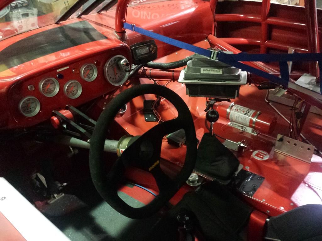
I picked this car up in August 2014 and put one race on it (NJMP JRRC). I knew it needed lots of attention, as it seems to have been neglected and the last tech sticker was from 2004, and the owner didn't know much about it. So as I go I'll post my progress here for the benefit of anyone else following in my footsteps. Feel free to comment or make an suggestions, this is my first tube frame car, and I'm learning something new every day! I didn't know if I should post this thread here or in the GTA section, so move it if necessary...
I picked up the car in Sheboygan, Wisconsin, and immediately got to work prepping it for it's first track day. We are pretty low budget around here, but the first order of business was to get our sponsors on the car:
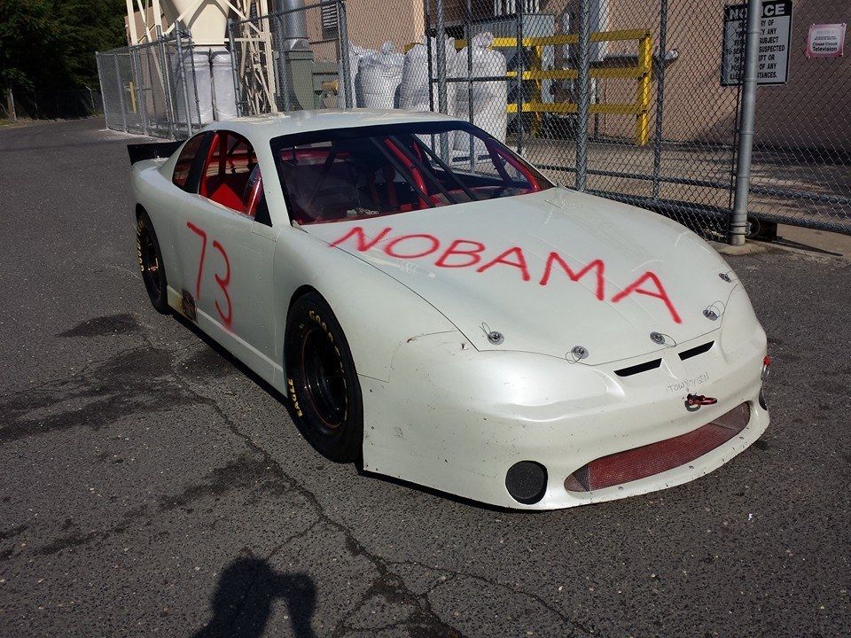
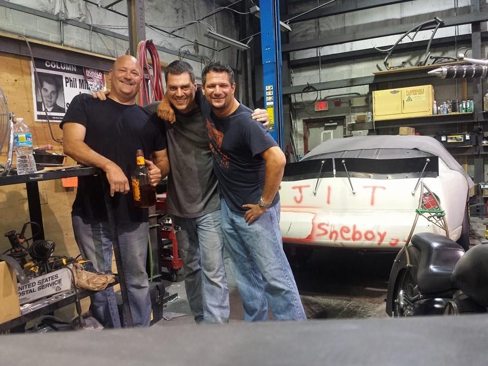
A quick drunken celebration to Christen the car with a little fireball (or allot). That's me in the center, my buddy Doc (left) who loves to help work on the car, and Al, our token Jew on the right. He doesn't have much mechanical skill but since we have converted him to Republican his people no longer want him so we had to take him in.
We had to make a last min sponsor change for the Porsche Club event, apparently political correctness counts with those guys...

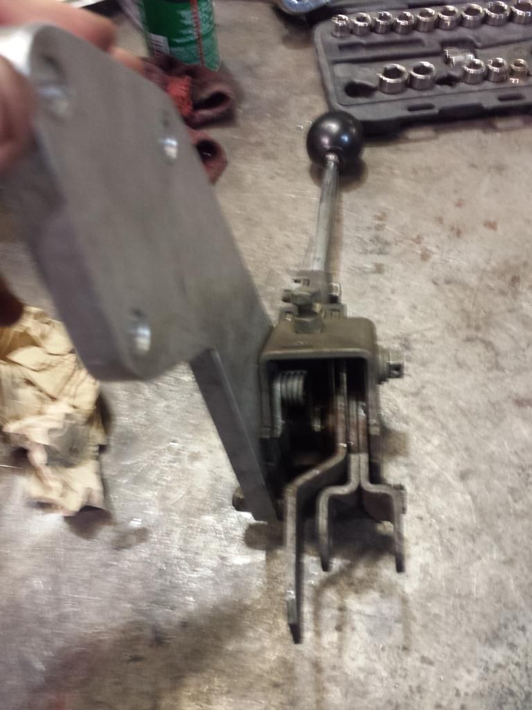
First event went without a hitch, except we had no reverse. With some help here, we tracked the problem down to the junk Hurst shifter in the car. It was replaced with a Long, and all was well.
Next was to take it out for a race. I brought it up to Watkins Glen for the last race of the season, but a Watts Link failure on Friday put me out for the weekend. No big deal, I knew I'd have issues.
Some bracing fixed it right up:
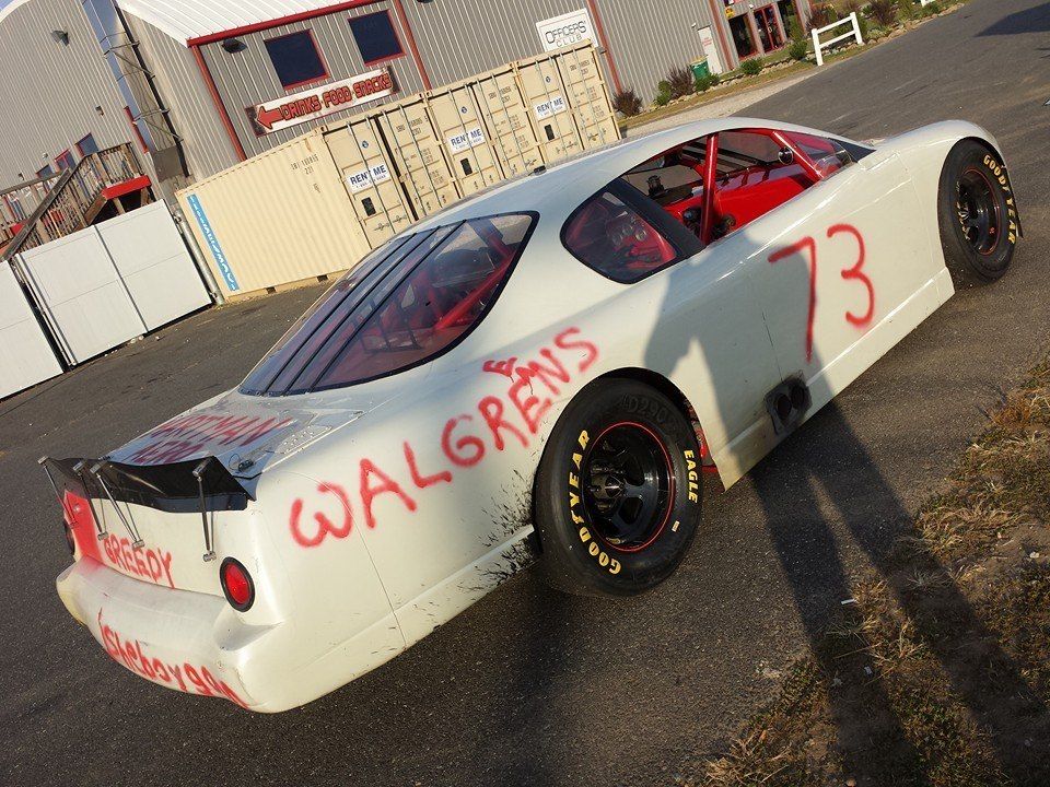
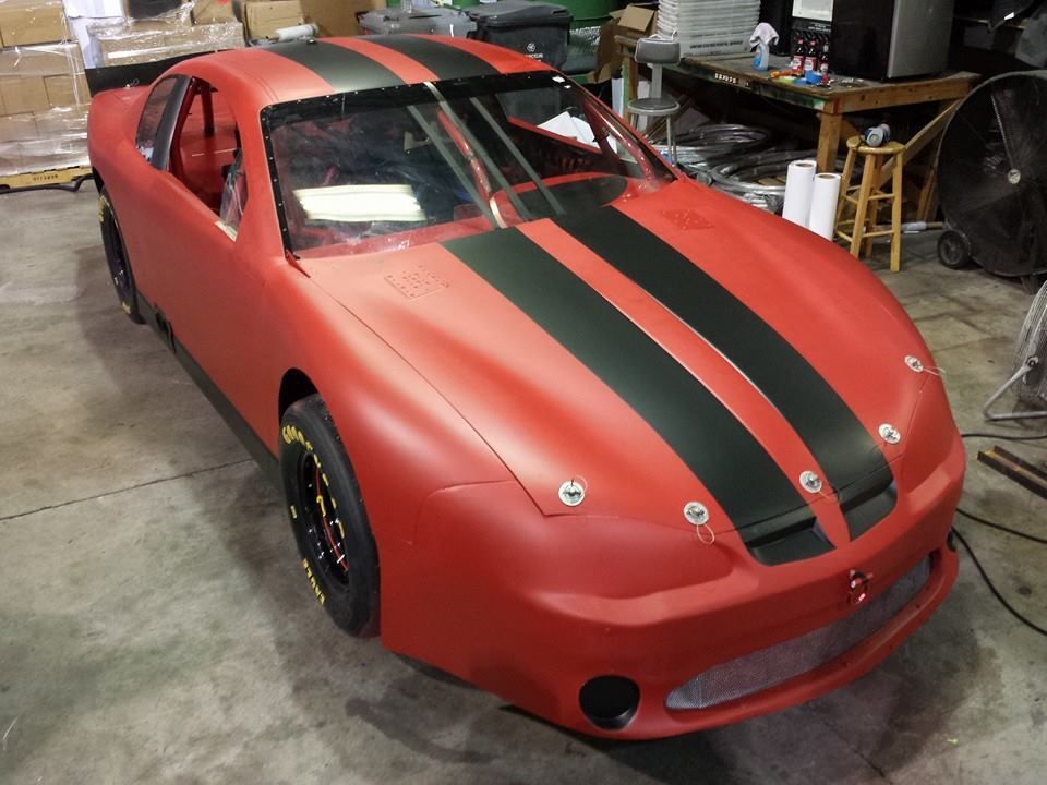
Before our first race weekend, we decided to throw some real paint on there. I've had a hair up my butt to plastidip a car for years now, so we figured this would be a good opportunity. It can't get any uglier, right?
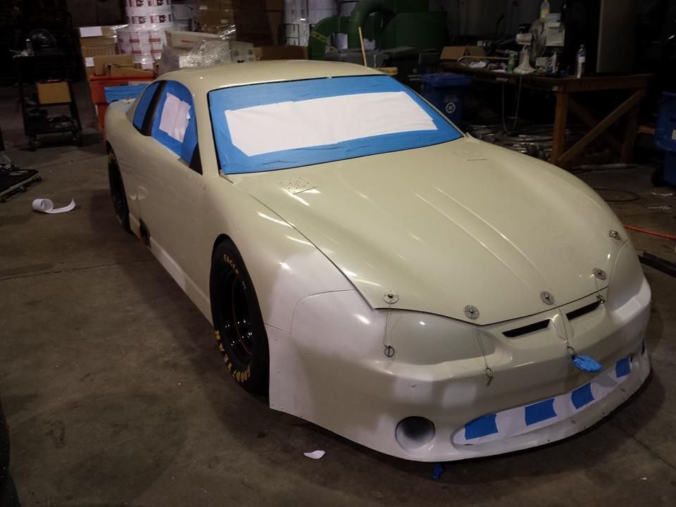
7 coats of plasti dip. I initially had a heart attack over how much I had to spray (5 gallons!!!) but after some research it turns out it only added about 5 lbs.

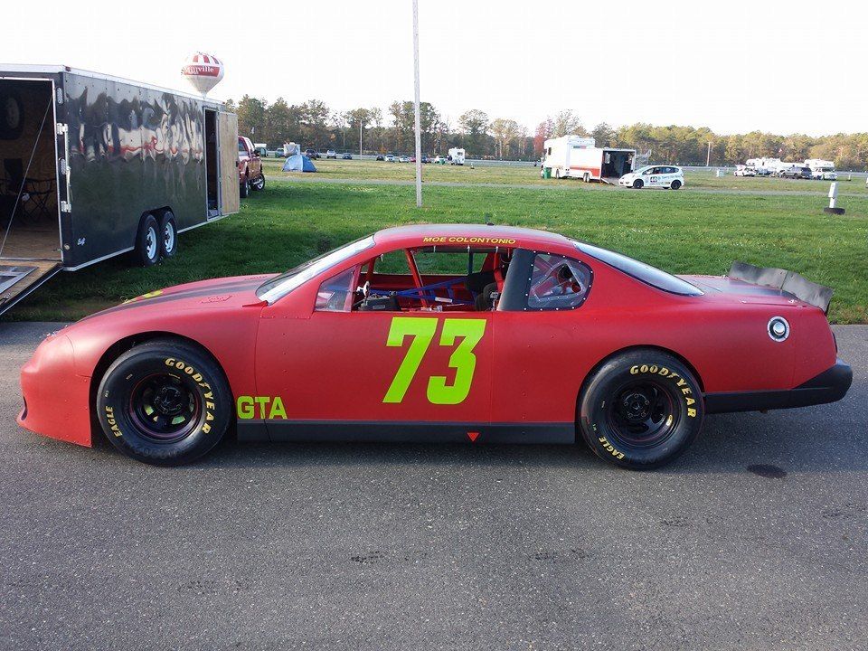
First real race weekend was at New Jersey Motorsports Park, for the JRRC season ender. Car ran great, but I knew it needed some changes. On the scales it was really left side heavy, and it didn't like to turn right at all. I wrapped up the season, and proceeded to start the tear down.
I picked this car up in August 2014 and put one race on it (NJMP JRRC). I knew it needed lots of attention, as it seems to have been neglected and the last tech sticker was from 2004, and the owner didn't know much about it. So as I go I'll post my progress here for the benefit of anyone else following in my footsteps. Feel free to comment or make an suggestions, this is my first tube frame car, and I'm learning something new every day! I didn't know if I should post this thread here or in the GTA section, so move it if necessary...
I picked up the car in Sheboygan, Wisconsin, and immediately got to work prepping it for it's first track day. We are pretty low budget around here, but the first order of business was to get our sponsors on the car:
A quick drunken celebration to Christen the car with a little fireball (or allot). That's me in the center, my buddy Doc (left) who loves to help work on the car, and Al, our token Jew on the right. He doesn't have much mechanical skill but since we have converted him to Republican his people no longer want him so we had to take him in.
We had to make a last min sponsor change for the Porsche Club event, apparently political correctness counts with those guys...
First event went without a hitch, except we had no reverse. With some help here, we tracked the problem down to the junk Hurst shifter in the car. It was replaced with a Long, and all was well.
Next was to take it out for a race. I brought it up to Watkins Glen for the last race of the season, but a Watts Link failure on Friday put me out for the weekend. No big deal, I knew I'd have issues.
Some bracing fixed it right up:
Before our first race weekend, we decided to throw some real paint on there. I've had a hair up my butt to plastidip a car for years now, so we figured this would be a good opportunity. It can't get any uglier, right?
7 coats of plasti dip. I initially had a heart attack over how much I had to spray (5 gallons!!!) but after some research it turns out it only added about 5 lbs.
First real race weekend was at New Jersey Motorsports Park, for the JRRC season ender. Car ran great, but I knew it needed some changes. On the scales it was really left side heavy, and it didn't like to turn right at all. I wrapped up the season, and proceeded to start the tear down.
 03-02-2015, 03:29 PM
#2
Burning Brakes
Thread Starter
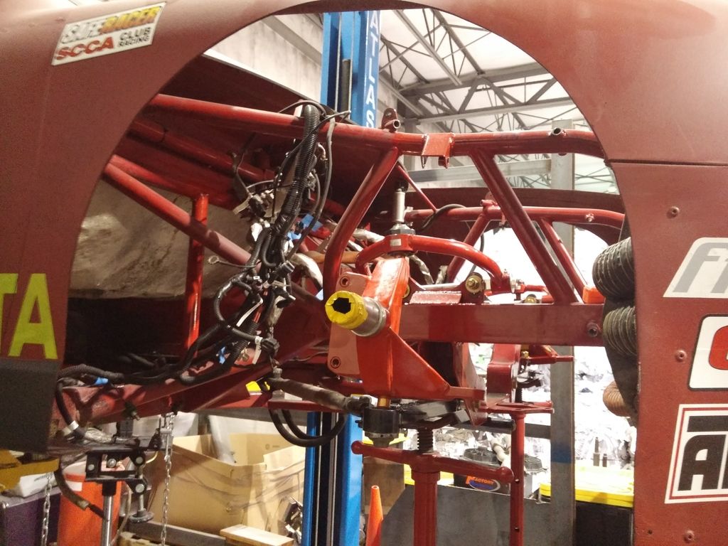
So the first order of business was to find the center of this thing. Woody down at Bemco was great, and answered every one of my stupid questions. We shot a laser down the center of the car, as measured from the center section:

As it turns out, the right side Lower Control Arm mount was offset 3" inboard, and the upper suspension mount was 1.25" inboard. A previous owner had put a 2" longer Lower Control Arm on the right to compensate.
My solution (with plenty of forum help) was to make plates and simply move the LCA mount outboard 3", and rotate the upper shock mount outboard 1.25".
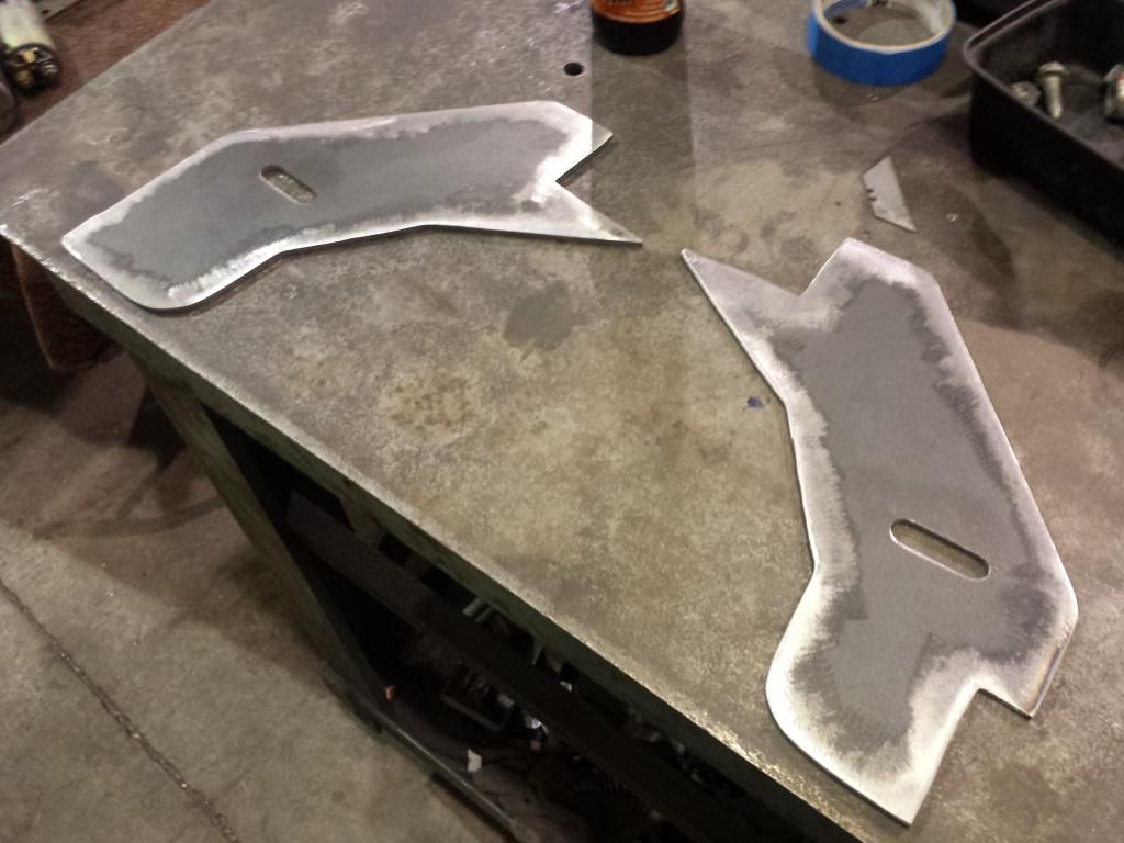
I got lazy and just welded plates over the existing plates after cutting a relief for the bolt clearance.
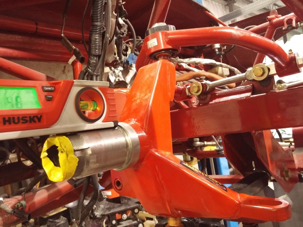
This whole process was made much easier with a self leveling laser that shot a line both horizontally, and vertically straight up. Easier than screwing with a plumb bob. The car must be shimmed level on the lift for this to work.
Turns out my spindles were different inclinations, which explains why I had an inch of camber shim on one side, and nothing on the left. Caster was also wacky.
I initially ordered Howe roadrace spindles, but they would require changing the front calipers. I just decided to have Port City fab a set of Roadrace Spindles for me that will mount the Wilwood Integras that I currently have. I'd love to upgrade the brakes, but that stupid budget thing keeps rearing it's ugly head.
Next was to get the engine out of the way. I drink regularly so I find it best to label every plug and wire, even the obvious stuff.
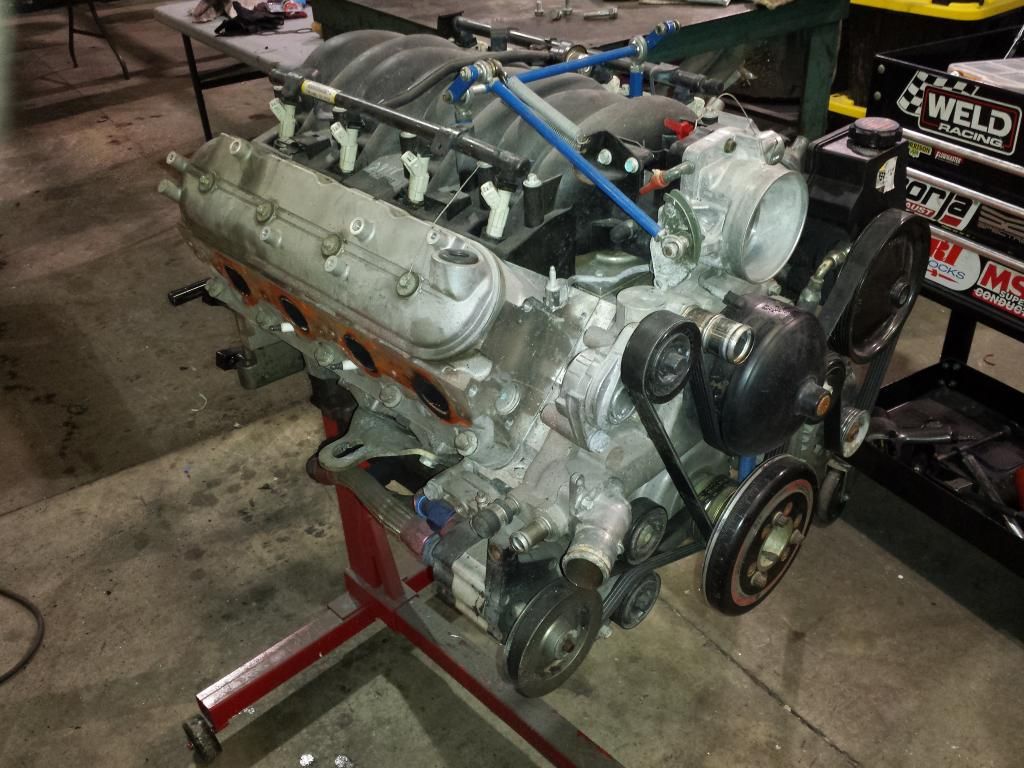
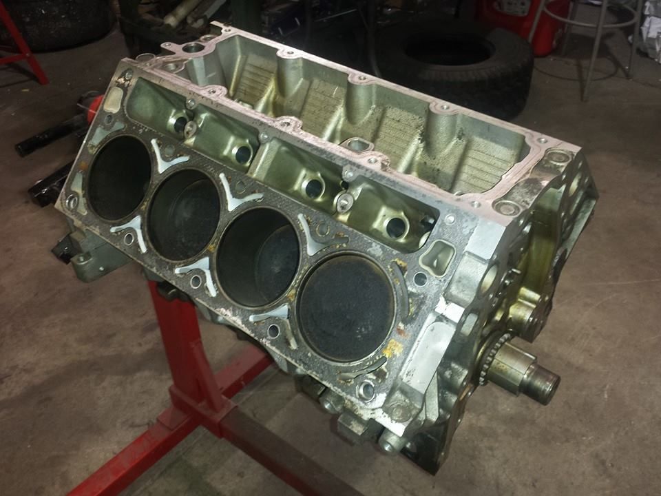
I will build a new modified tour (LS6) engine using my spare LS1 from my T1 Corvette.
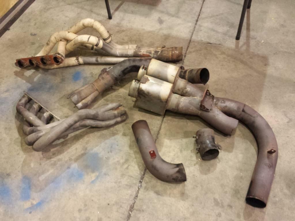
Exhaust is junk, I'll get a new system.
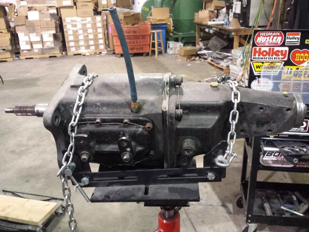
Transmission looks to be a T10 in a Tex case. Leaking like crazy and lots of chipped gears. Looks like I'll be getting a G101A from GForce.
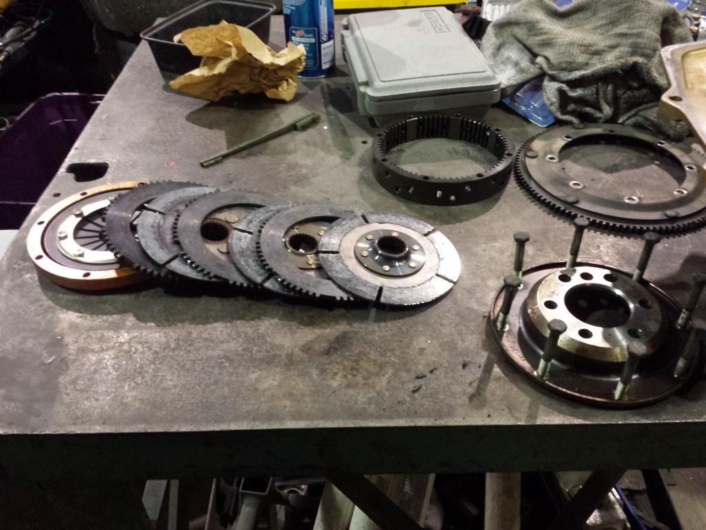
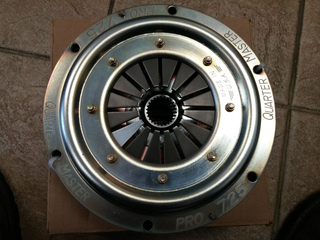
Clutch is cooked:
I sent my shocks out to OC Shocks to get dynoed. They checked out, but the valving was different in each shock. They set me straight.

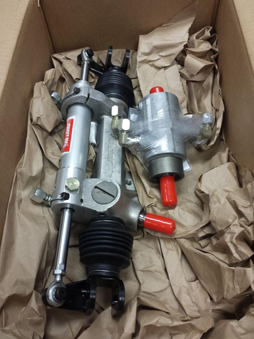
Power steering rack went out to sweet for a rebuild, and re-valve to quicken the steering a hair. I'm tall (6'3") and like to use a smaller steering wheel so it's not in my lap/knees.
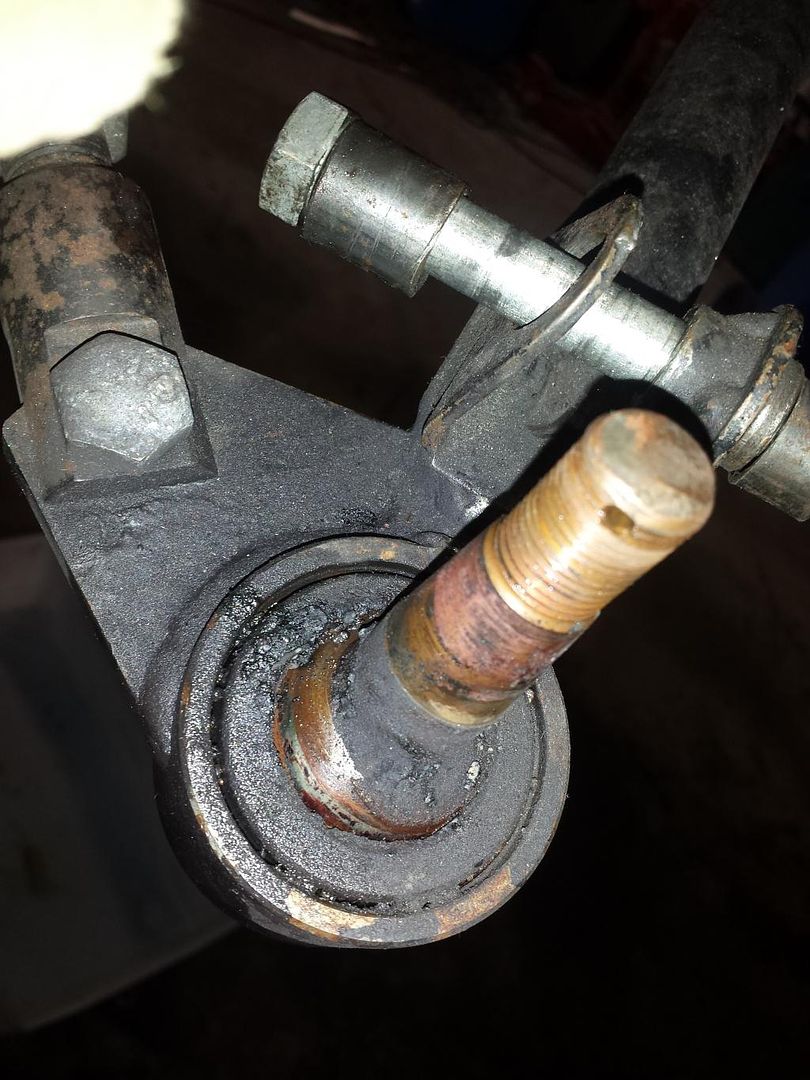
Ball joints were all shot. Once again, CJ at Port City fixed me up:
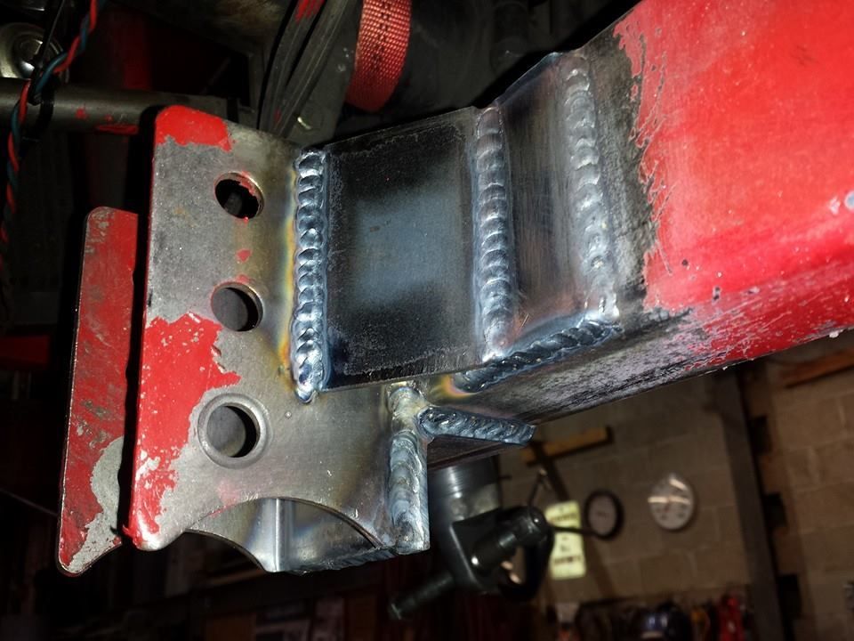
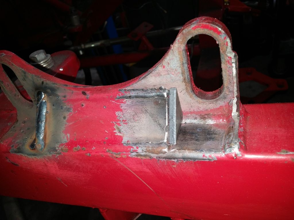
I also found plenty of poor welding that needed to be corrected.
As it turns out, the right side Lower Control Arm mount was offset 3" inboard, and the upper suspension mount was 1.25" inboard. A previous owner had put a 2" longer Lower Control Arm on the right to compensate.
My solution (with plenty of forum help) was to make plates and simply move the LCA mount outboard 3", and rotate the upper shock mount outboard 1.25".
I got lazy and just welded plates over the existing plates after cutting a relief for the bolt clearance.
This whole process was made much easier with a self leveling laser that shot a line both horizontally, and vertically straight up. Easier than screwing with a plumb bob. The car must be shimmed level on the lift for this to work.
Turns out my spindles were different inclinations, which explains why I had an inch of camber shim on one side, and nothing on the left. Caster was also wacky.
I initially ordered Howe roadrace spindles, but they would require changing the front calipers. I just decided to have Port City fab a set of Roadrace Spindles for me that will mount the Wilwood Integras that I currently have. I'd love to upgrade the brakes, but that stupid budget thing keeps rearing it's ugly head.
Next was to get the engine out of the way. I drink regularly so I find it best to label every plug and wire, even the obvious stuff.
I will build a new modified tour (LS6) engine using my spare LS1 from my T1 Corvette.
Exhaust is junk, I'll get a new system.
Transmission looks to be a T10 in a Tex case. Leaking like crazy and lots of chipped gears. Looks like I'll be getting a G101A from GForce.
Clutch is cooked:
I sent my shocks out to OC Shocks to get dynoed. They checked out, but the valving was different in each shock. They set me straight.
Power steering rack went out to sweet for a rebuild, and re-valve to quicken the steering a hair. I'm tall (6'3") and like to use a smaller steering wheel so it's not in my lap/knees.
Ball joints were all shot. Once again, CJ at Port City fixed me up:
I also found plenty of poor welding that needed to be corrected.
03-02-2015, 03:30 PM
#3
Burning Brakes
Thread Starter
Next is to work on the rear of the car.
The rear was offset 1.5" right, and some extra frame work (maybe for a panhard bar?) was in the way of moving it any further left. I cut that crap out.
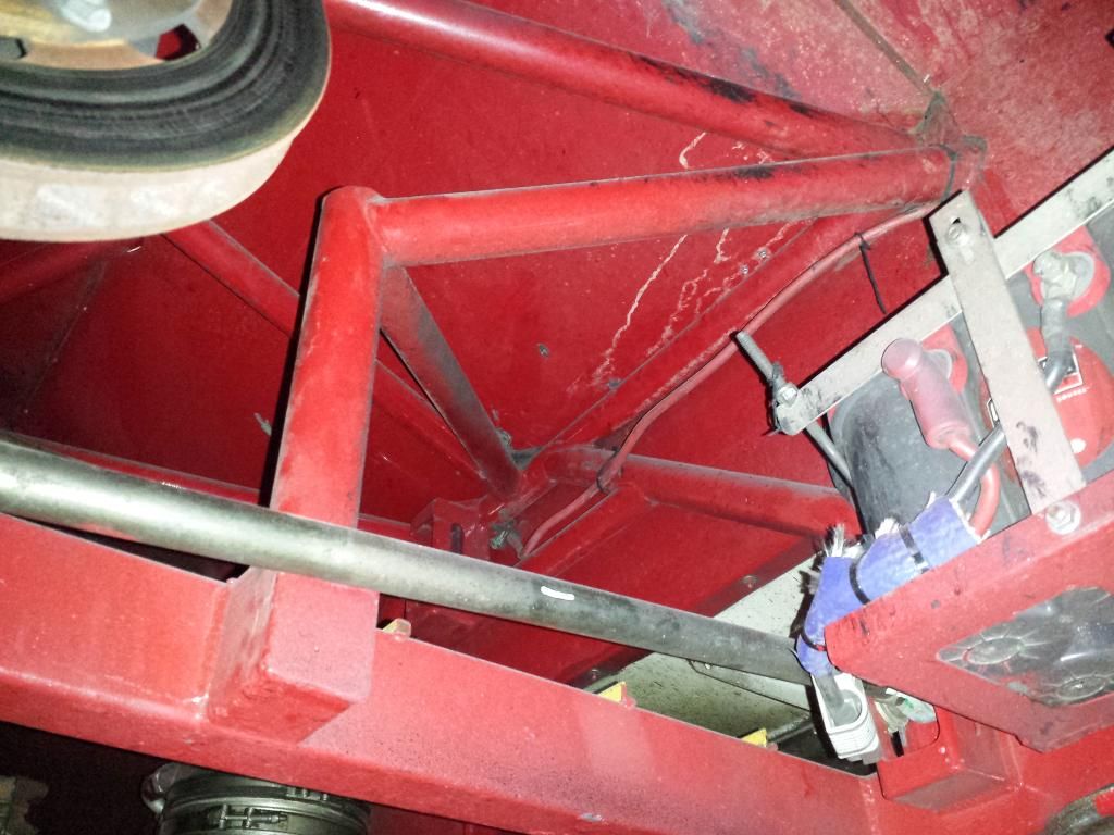
I needed more right side weight, so the battery and oil tank went from left to right. Once the extra frame work was out of the way I had the room. I also mounted the fire bottle and cool suit as far right as possible.

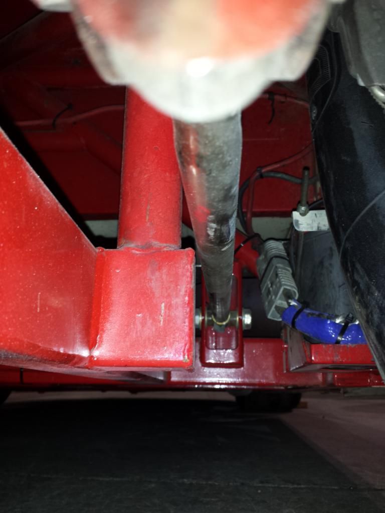
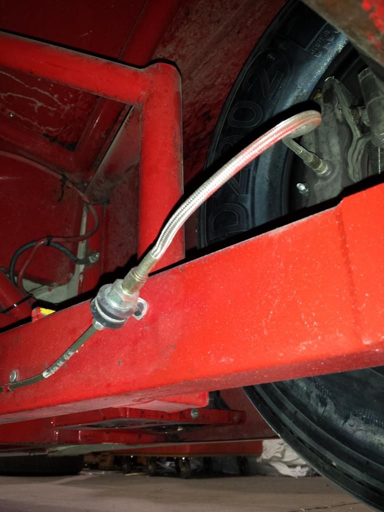
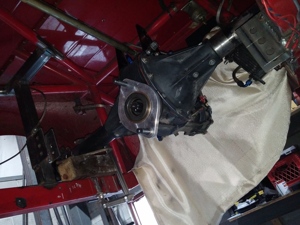
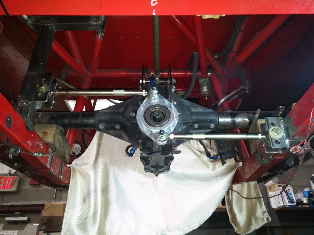
Now for the Watts Link. The bottom mounted Watts I had was the wrong tool for the job, so I bought one from Port City that centers on the drive line. This requires changing the mounting system, and I had to add some tubing. I'm hoping .090 wall 1.75" square is beefy enough. I may brace it against the frame rail. Any suggestions here?

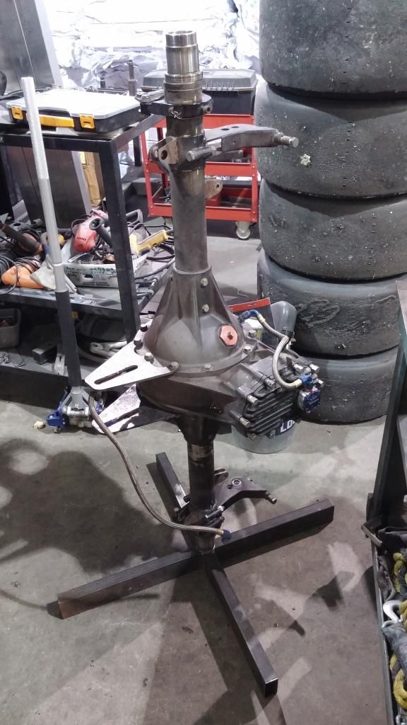
So here's where I am as of late February. Last night I pulled the rear and tonight I'll open it up to see what it needs. Think I'll be ready for the first race in 2 weeks?
The rear was offset 1.5" right, and some extra frame work (maybe for a panhard bar?) was in the way of moving it any further left. I cut that crap out.
I needed more right side weight, so the battery and oil tank went from left to right. Once the extra frame work was out of the way I had the room. I also mounted the fire bottle and cool suit as far right as possible.
Now for the Watts Link. The bottom mounted Watts I had was the wrong tool for the job, so I bought one from Port City that centers on the drive line. This requires changing the mounting system, and I had to add some tubing. I'm hoping .090 wall 1.75" square is beefy enough. I may brace it against the frame rail. Any suggestions here?
So here's where I am as of late February. Last night I pulled the rear and tonight I'll open it up to see what it needs. Think I'll be ready for the first race in 2 weeks?
03-02-2015, 03:35 PM
#4
Burning Brakes
Thread Starter
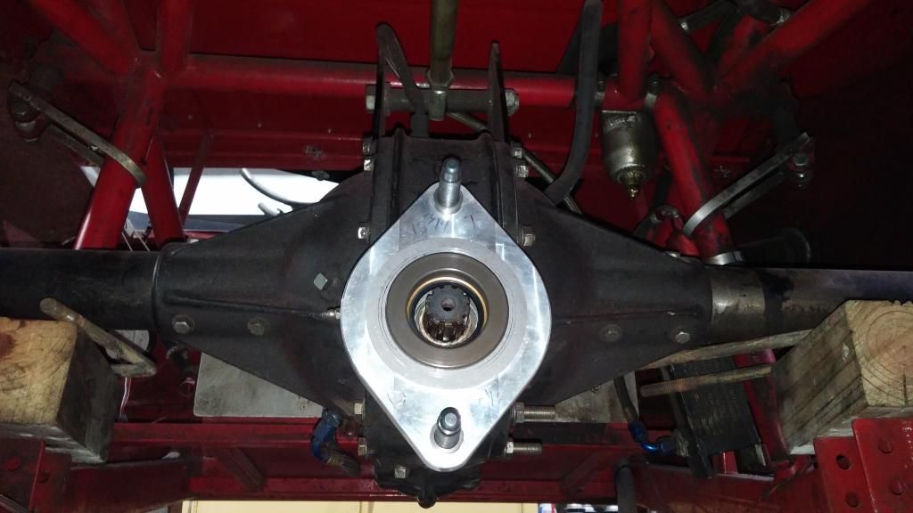
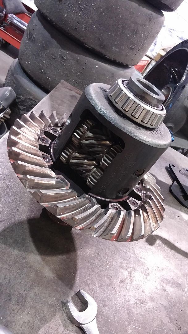
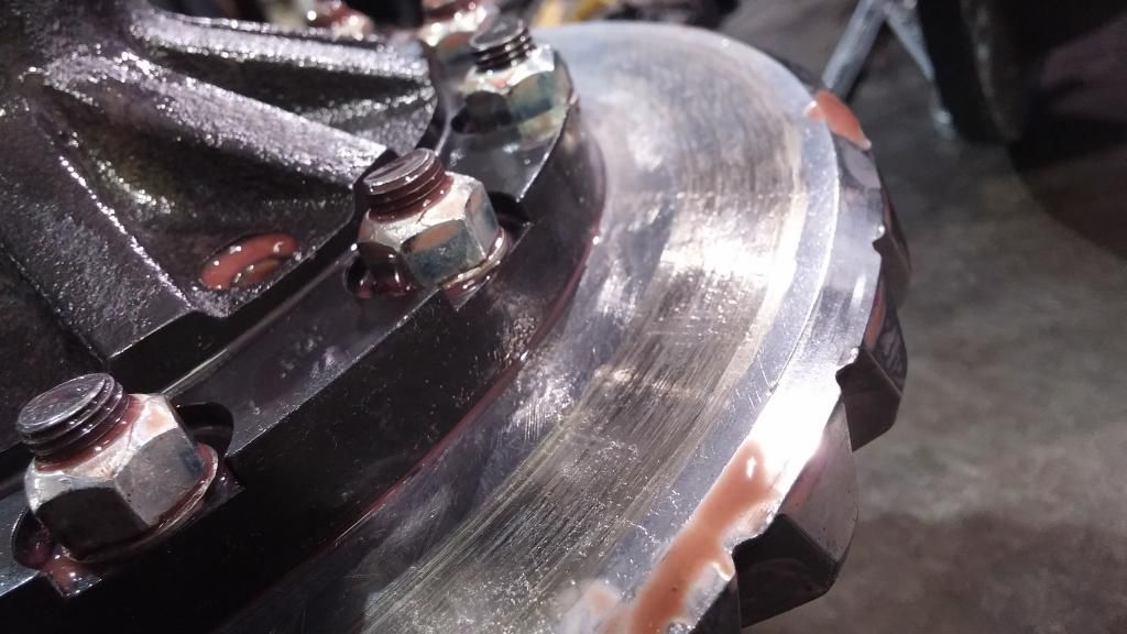
Opened the Diff tonight, and here's what I got. Turns out it's a Gleason rear which is what I want. Everything looked good so it's going back together once I get some new seals.
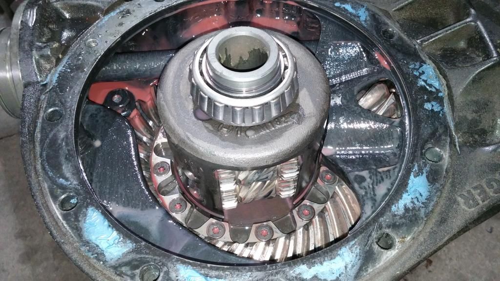
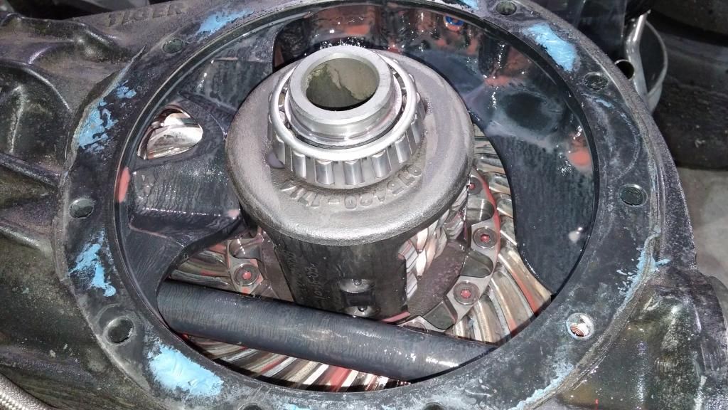
It looks like I probably had the wear pad adjusted a little too tight.
It looks like I probably had the wear pad adjusted a little too tight.
03-02-2015, 05:51 PM
#6
Burning Brakes
Thread Starter
Yeah no kidding! Love this thing though, much easier to work on than the vette and stupid fast for a fraction of the running costs.
Bosco check your PMs
Bosco check your PMs
03-03-2015, 03:10 AM
#7
Burning Brakes
Member Since: Apr 2005
Location: Cincinnati Ohio
Posts: 901
Likes: 0
Received 0 Likes
on
0 Posts

Very cool process. 
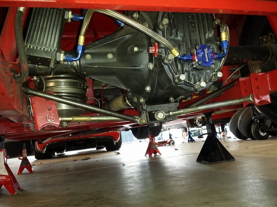
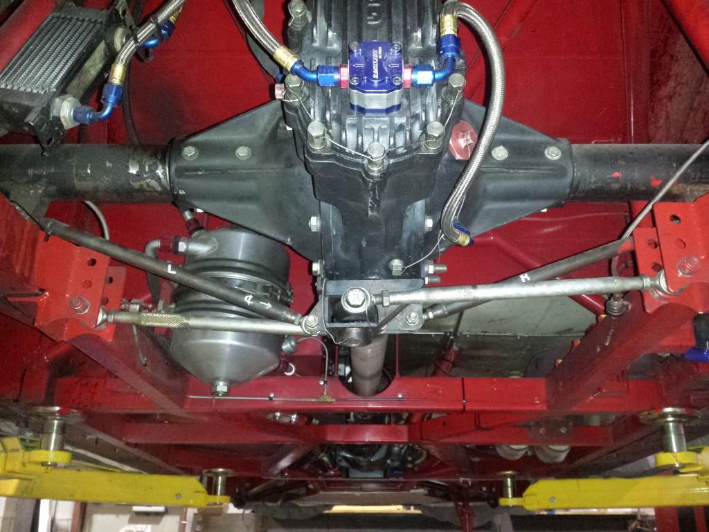
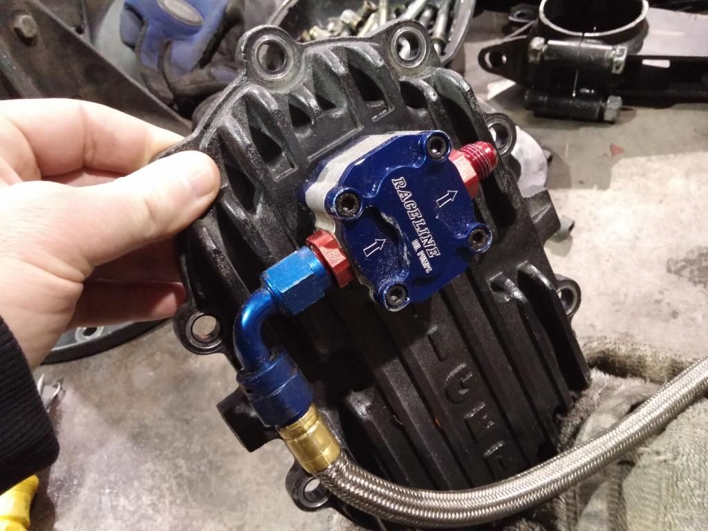
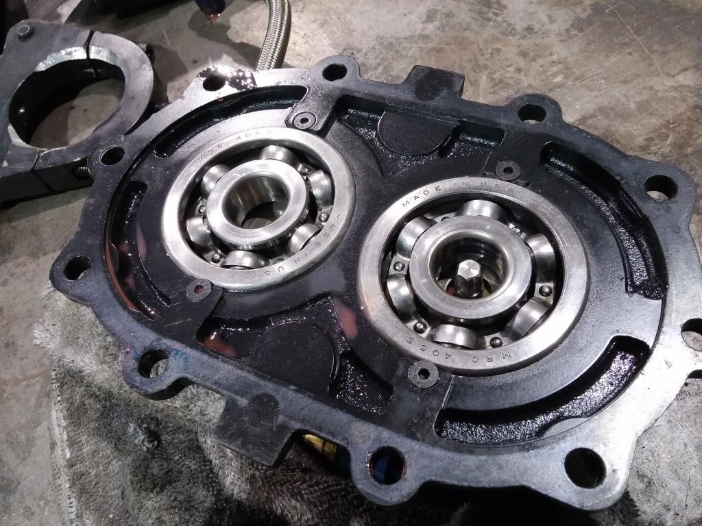
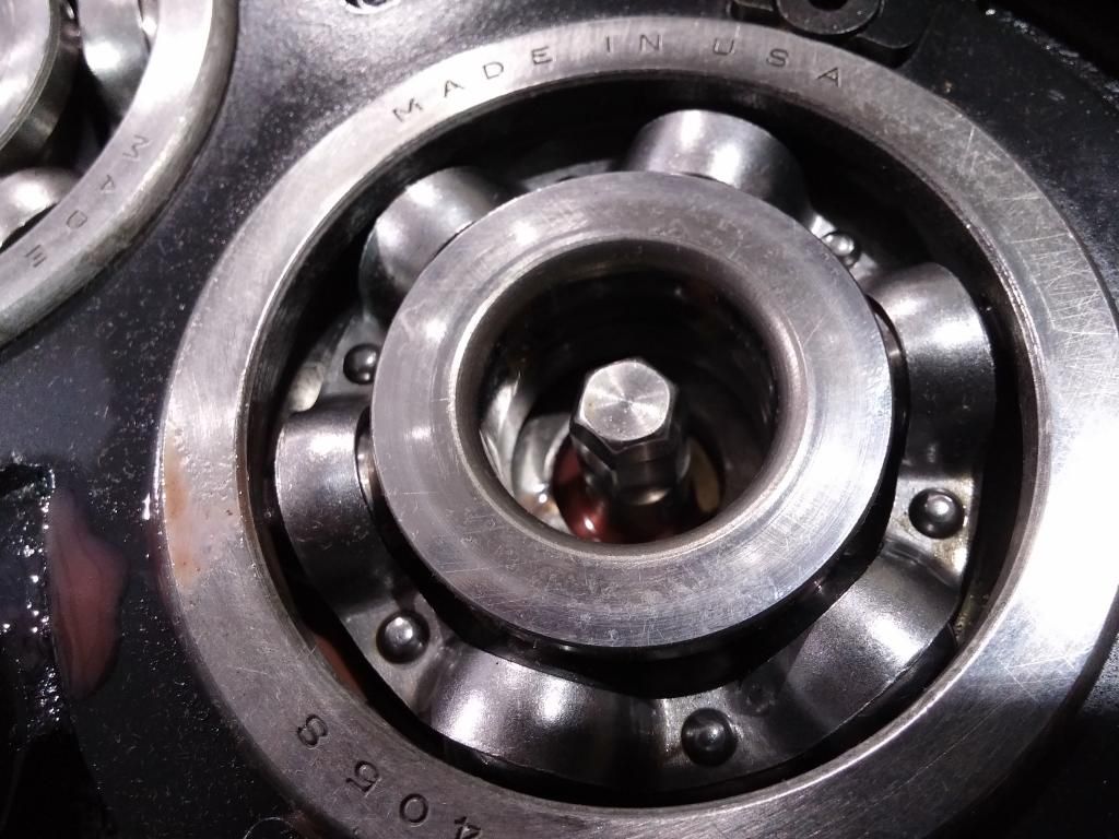
If you don't mind I am interested in more details on the integrated cooling pump that is attached to your Winters QC rear end 10 bolt cap. I have a similar set up w/o a pump and am interested in what the internals of the cap and gear set look like to make this work. It would be great if I could purchase a cap with the integrated pump and it's just plug and play. But I've got to imagine there is some type of special shaft end that drives the pump.
So if not to much of a hassle next time your changing out spur gears would you mind snapping and posting some images of the inside of the cover and the mating end on the spline shaft? Thanks
WEBZ
03-03-2015, 12:40 PM
#8
Drifting

moespeeds - LOVE the write-up...Doc and Al, the token Jew....LOL....too much fun!
I wish I could give you more input on the car...I just drive mine...I like the plasti-dip...I was curious about the weight...only 5 pounds? Crazy...I can lose that in a day LOL.
I wish I could give you more input on the car...I just drive mine...I like the plasti-dip...I was curious about the weight...only 5 pounds? Crazy...I can lose that in a day LOL.
 03-03-2015, 03:47 PM
#10
Instructor


Member Since: Feb 2010
Posts: 109
Likes: 0
Received 0 Likes
on
0 Posts

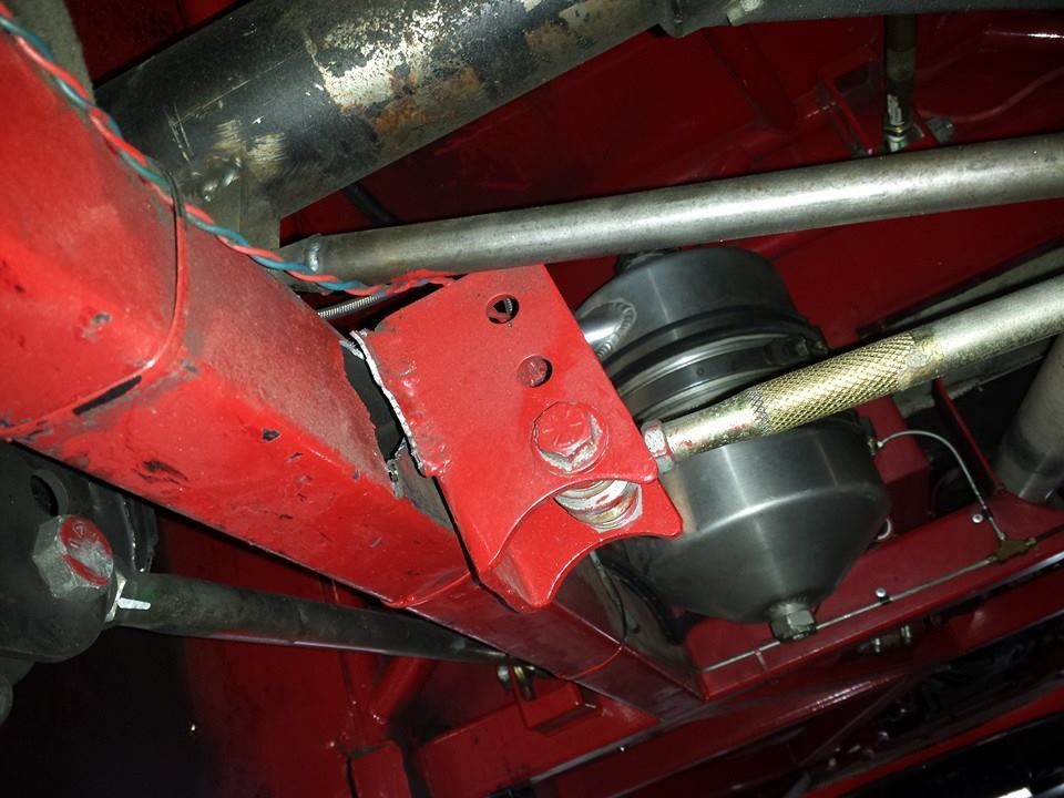
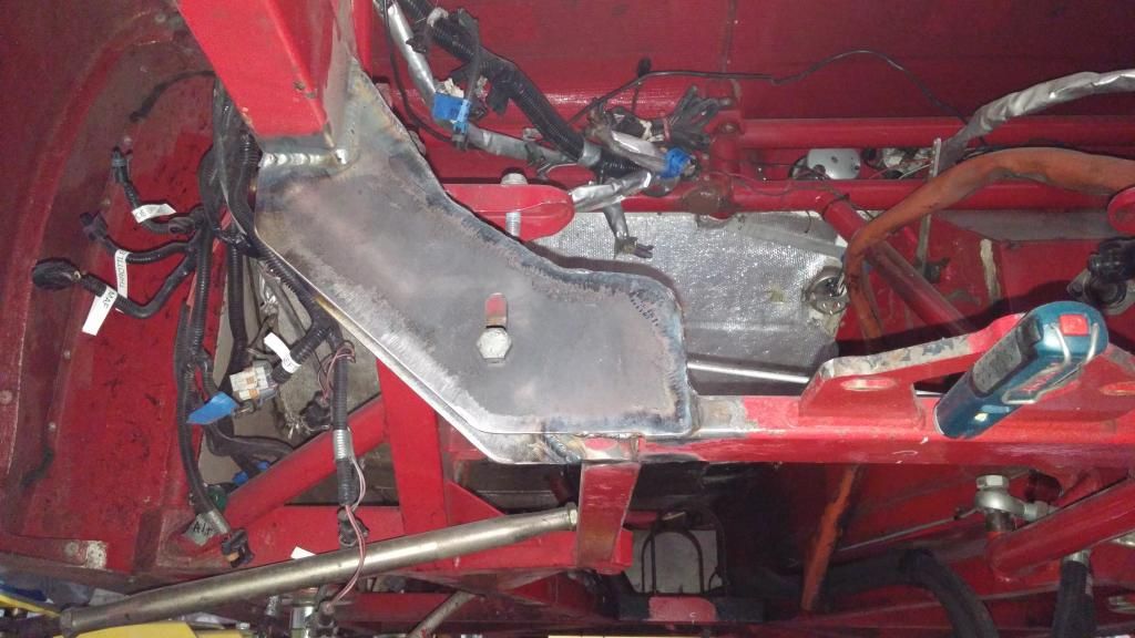
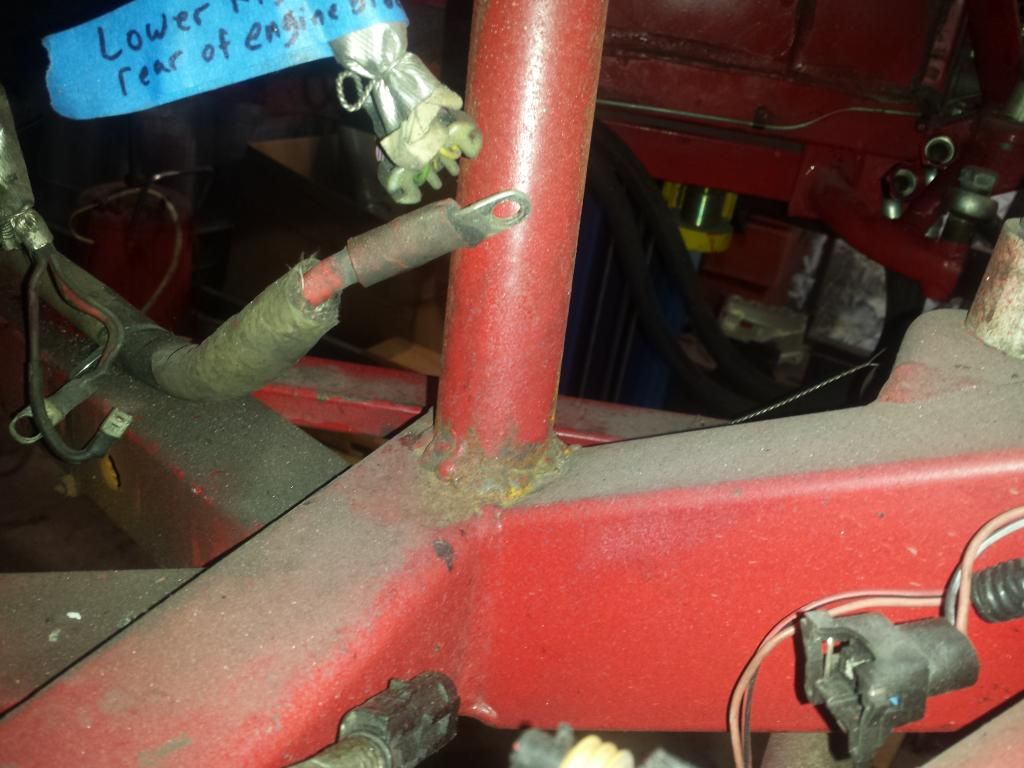
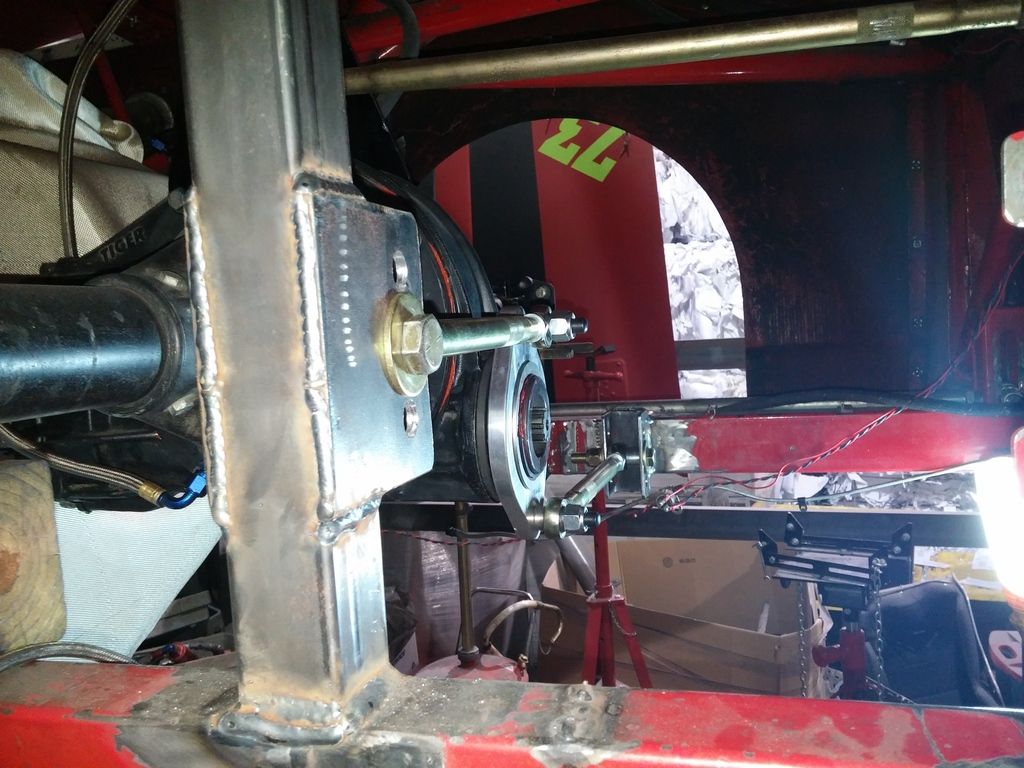
Strengthen these front mounts now while you have it all apart. It WILL fail the same way your watts link did. I had to make an emergency trip to A&E Race Cars to get fixed up when mine failed at VIR.
03-03-2015, 03:56 PM
#11
Burning Brakes
Thread Starter
03-10-2015, 04:27 PM
#12
Burning Brakes
Thread Starter
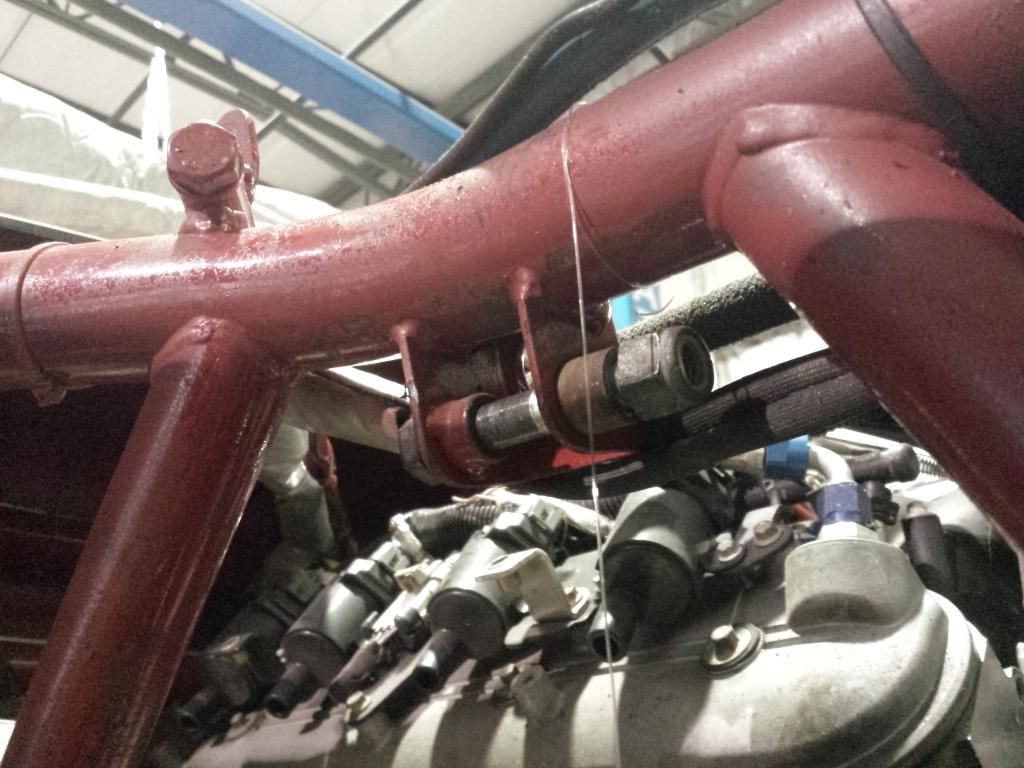
I need some help/advice on setting up this Watts Link. So as you see below I got the Port City setup that centers on the driveline. My rear frame rails are offset left 1", and when I welded up those brackets for the Watts I did not take this into account. CJ at Port City is telling me that the upper and lower Watts arms must be the same length so they don't fight each other? But Woody at Bemco says it doesn't matter, the link has no idea how long the arms are so long as they run parallel with the drive axle and run more or less level at static ride height. He also told me to cant the Watts off vertical a little bit as shown. So which is it? Vern help!

03-10-2015, 06:22 PM
#13


With the links not equal length the rear end will move a bit sideways when the suspension cycles. Same thing if they are not parallel (or opposite angles) at static ride height. Whether you notice it or not is another question.
The easiest thing to do is set it up as-is and try it out. If you want to visually see, and measure the sideways movement just pull the coilovers and cycle the suspension.
The correction, if you decide it's needed is to replace one of the chassis mounts so the links can be made equal. There are offset pinion mounts, but I bet it will move the pivot more than an inch so problem will not be solved. If you replace the chassis mounts I would suggest considering a watts mount with roll center adjustment. However, that will require an electric pump since it replaces the rear cover.
http://www.dpiracingproducts.com/com...k-panhard-bar/
03-18-2015, 10:52 AM
#14
Burning Brakes
Thread Starter
A buddy ran it through a CAD program, and the total deviation though 3.5" of suspension travel was only .030", negligible. It's small enough for me to be lazy and not cut off/re-make the mount on once side.
03-18-2015, 02:47 PM
#15

I'd extend your chassis-side 3rd link mount down more if possible. You'll find that you get the best bite out of corners with that link as close to the top of the housing as possible, and only 2 or 3 degrees of angle. You may not need to extend it, just make sure that you can still get some angle on that link when the car is at desired ride height and the link is bottomed out on the housing.
Last edited by LateBreak; 03-18-2015 at 02:54 PM.
03-18-2015, 02:50 PM
#16
Also, if your lower arms on the front suspension have aluminum links, be sure to replace with steel as the aluminum will deflect more under braking.
For front tie rods, check out Coleman's EZ-just links, they're much easier than using jam nuts and only about $20 each.
For front tie rods, check out Coleman's EZ-just links, they're much easier than using jam nuts and only about $20 each.
04-28-2015, 09:24 AM
#17
Burning Brakes
Thread Starter
Finally got the Watts link all setup, so the rear is pretty much done.
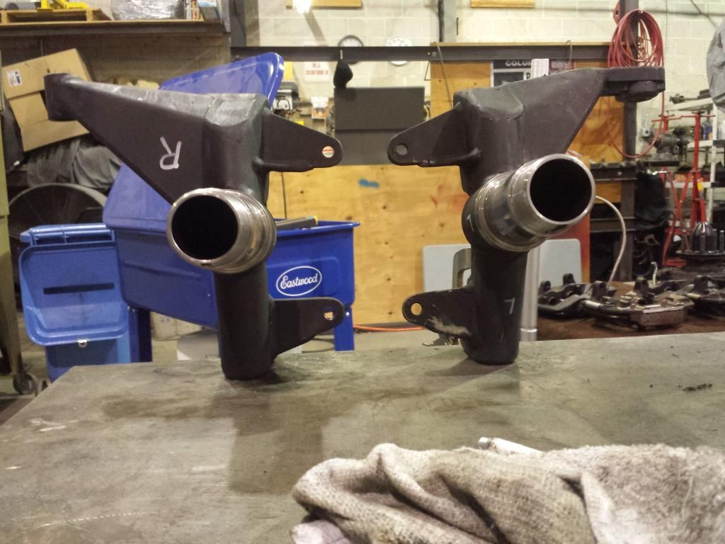
Port City Custom Road Race Spindles, Port City upper control arms, Howe lower control arms. Like Christmas over here...
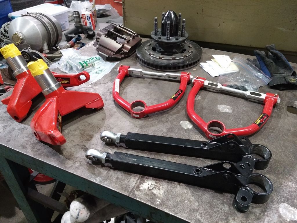
Question about these uppers, see how one of the slots is cut to accept a slug (for caster?), but the other is blank. What's up with that? Do I just run one slug?
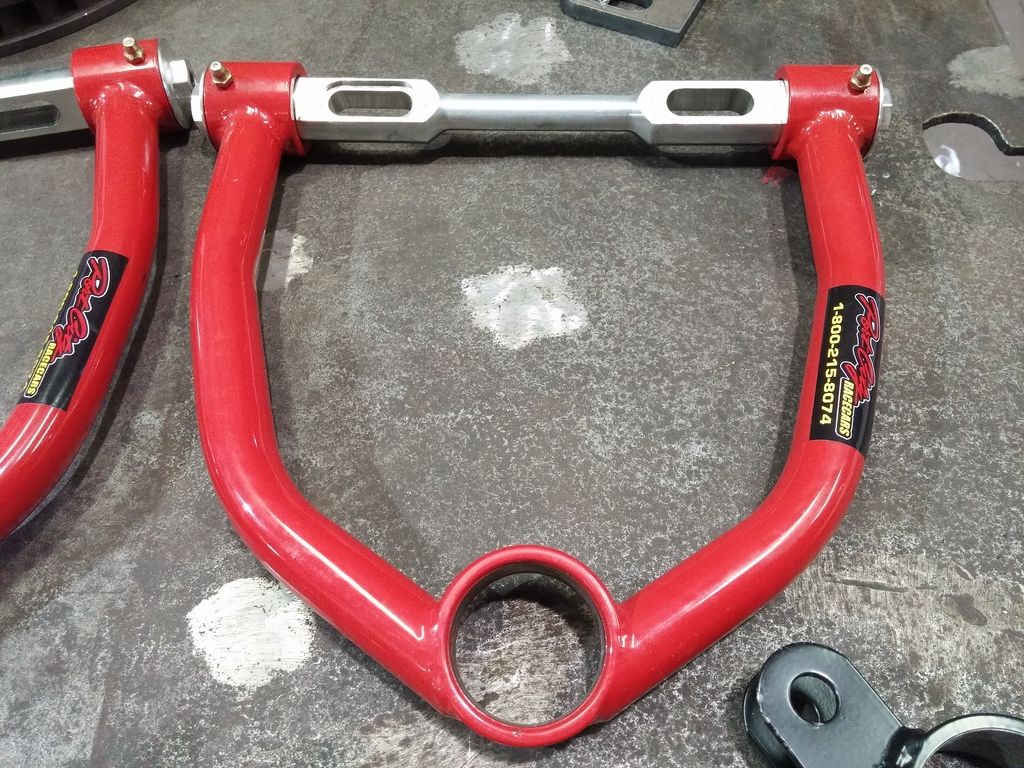
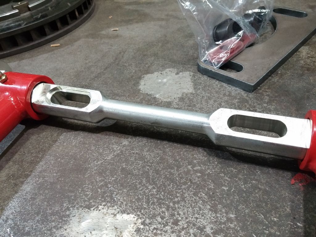
Port City Custom Road Race Spindles, Port City upper control arms, Howe lower control arms. Like Christmas over here...
Question about these uppers, see how one of the slots is cut to accept a slug (for caster?), but the other is blank. What's up with that? Do I just run one slug?
04-28-2015, 09:25 AM
#18
Burning Brakes
Thread Starter
I put the spindles and control arms on the car tonight, and then jacked them up to approximate static ride height, and I've got -8* of camber! It's at least equal right to left, but I'm not sure where else I screwed up here. So my options are to shorten up the lower control arms, or lengthen the uppers. The uppers are 9" angled, lowers I'll have to measure in the morning as I forgot tonight. Tomorrow I want to throw the wheels on to get an idea of what my track width is, as it may help with my decision.
Any advice?
Any advice?
04-28-2015, 09:26 AM
#19
Burning Brakes
Thread Starter
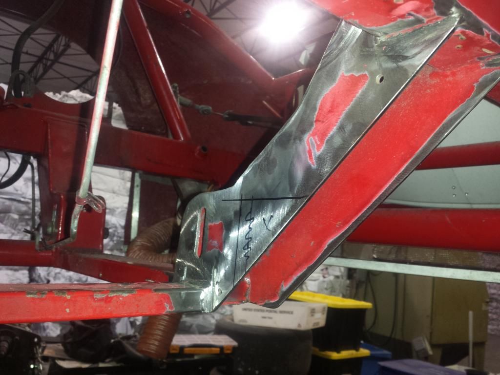
I moved the uppers to the outboard side of the mounts, and it solved the problem. It also will allow me to move the engine over to center. The way they were mounted originally, the headers on the right side were just about touching the back of the UCA, forcing the engine 3/4" to the already too heavy left side of the car. I had to cut away some angle bracing the mount, so I added some back in the center. Hopefully it will hold!
04-28-2015, 09:28 AM
#20
Burning Brakes
Thread Starter
I ordered my transmission from GeForce, got a recon G101A and ran a 1.7 first gear, and let them figure out the rest. Anything is better than what I had. Since my 5.5" Quartermaster needed a new button wheel and ring gear I decided to just get a whole new 7.25" setup.
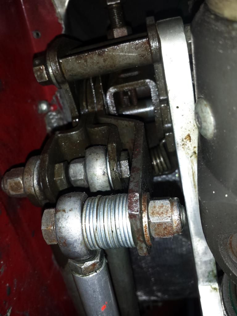
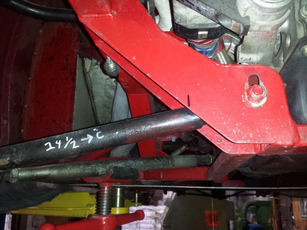
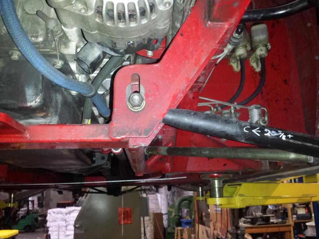
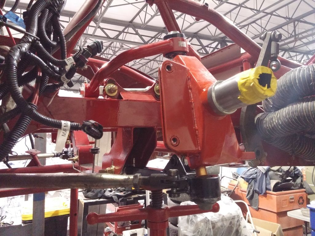
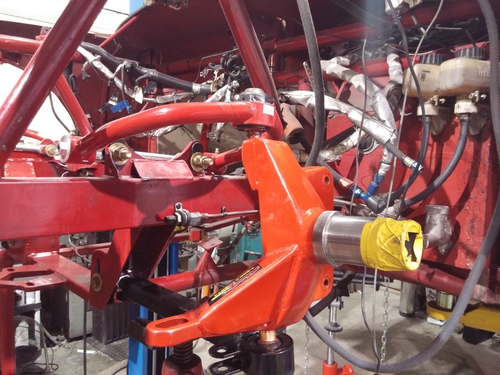
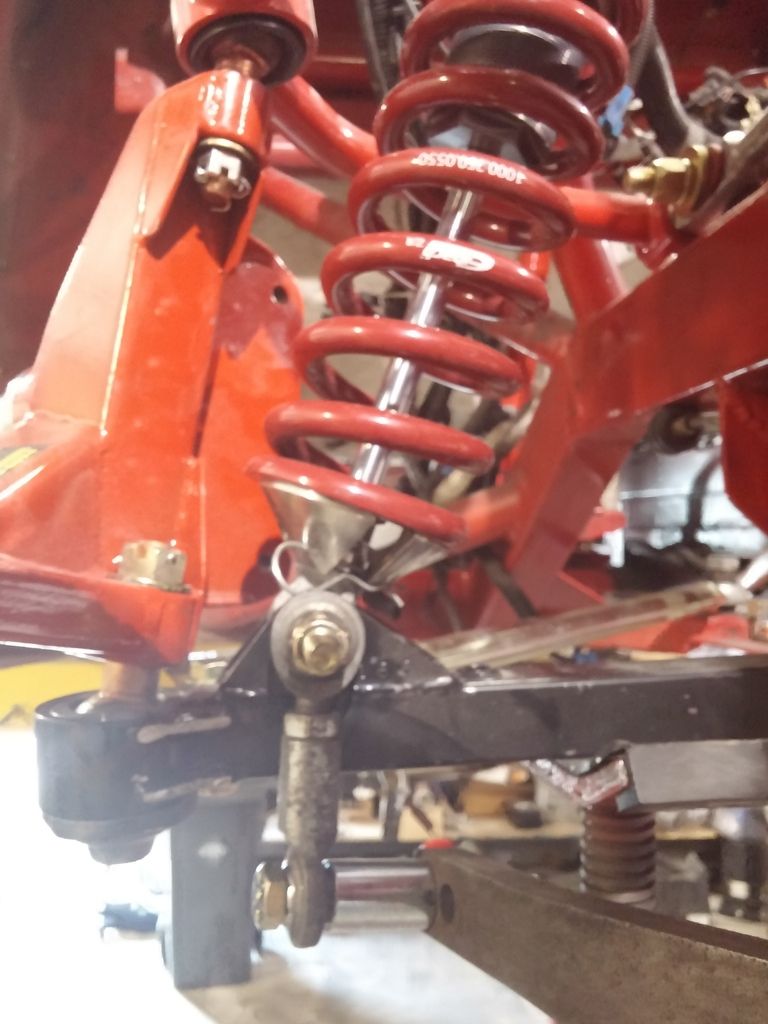
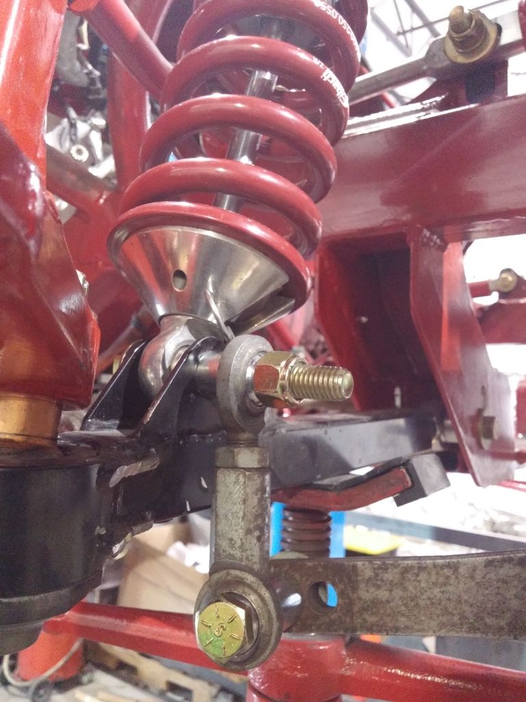
Got the front end mostly sorted out but have a few questions. First off, since moving the control arm and suspension mounts outboard on the passenger side to get rid of the offsets, now the sway bar doesn't line up. Is this a Kosher solution, or should I cut the whole sway bar mount off and move it over? Ignore the long shock lower mounting bolt it needs to be turned around it will interfere with steering as is. Note the 1.5" spacer I'm using where the end-link attached to the sway bar:
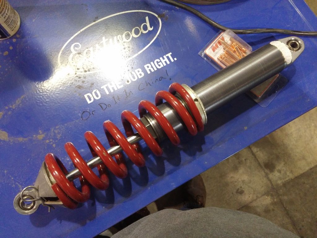
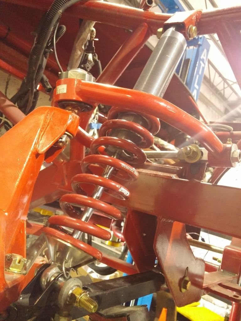
Another question, with these Carrera shocks, they were originally mounted heavy side down. Any reason why I can't run them upside-down as shown to save unsprung weight? I know I will have to cut a small clearance in the upper mount.
As always, any input is appreciated.
Got the front end mostly sorted out but have a few questions. First off, since moving the control arm and suspension mounts outboard on the passenger side to get rid of the offsets, now the sway bar doesn't line up. Is this a Kosher solution, or should I cut the whole sway bar mount off and move it over? Ignore the long shock lower mounting bolt it needs to be turned around it will interfere with steering as is. Note the 1.5" spacer I'm using where the end-link attached to the sway bar:
Another question, with these Carrera shocks, they were originally mounted heavy side down. Any reason why I can't run them upside-down as shown to save unsprung weight? I know I will have to cut a small clearance in the upper mount.
As always, any input is appreciated.