OK, how do I wire a four pin GM coil to act like a regular coil?
 09-08-2008, 06:21 PM
#1
Race Director

Thread Starter
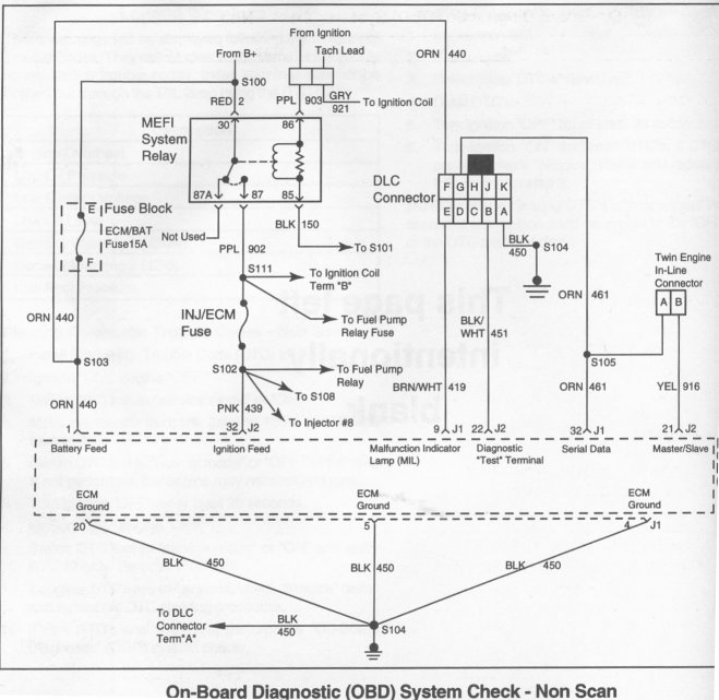
See attached wiring diagram. What pin on the GM coil does the POS wire go to and what pin does the NEG/GND wire go to?
I am suspecting the 902 PPL wire pin is where the NEG/GND wire goes, but I am not sure what to do with the 3 PNK and 121 BRN wire, do i connect the + wire to both 3 PNK and 121 BRN, or to 121 BRN only?

Thanks,
Doug
I am suspecting the 902 PPL wire pin is where the NEG/GND wire goes, but I am not sure what to do with the 3 PNK and 121 BRN wire, do i connect the + wire to both 3 PNK and 121 BRN, or to 121 BRN only?
Thanks,
Doug
 09-08-2008, 08:24 PM
#2
Race Director
Member Since: Feb 2007
Location: northern california
Posts: 13,609
Received 6,521 Likes
on
3,001 Posts
C2 of Year Finalist (track prepared) 2019

Doug, having absolutely no experience with the 4 wire coils, I'll bite.....
I'd tie 3 PNK and 902 PPL together and to your points or whatever ignition controller you use.
121 BRN goes to +12V
What looks like a gray wire could be left unconnected, but covered since it will have +12V on it via 121 BRN.
Good luck,
Jim
I'd tie 3 PNK and 902 PPL together and to your points or whatever ignition controller you use.
121 BRN goes to +12V
What looks like a gray wire could be left unconnected, but covered since it will have +12V on it via 121 BRN.
Good luck,
Jim
09-08-2008, 09:24 PM
#3
Race Director
Thread Starter
The grey wire is a tach signal and won't be used.
Another question:
On an old standard coil, what does the internal wiring look like? Does the + terminal connect to both primary and secondary coils?. I know the primary coils other connection is the - terminal, what about the secondary coil, does it terminate at the - terminal also or to the iron core that sends out the spark?
Doug
09-09-2008, 12:03 AM
#4
Drifting

Member Since: Mar 2005
Location: Iowa
Posts: 1,300
Likes: 0
Received 0 Likes
on
0 Posts
The grey wire is a tach signal and won't be used.
Another question:
On an old standard coil, what does the internal wiring look like? Does the + terminal connect to both primary and secondary coils?. I know the primary coils other connection is the - terminal, what about the secondary coil, does it terminate at the - terminal also or to the iron core that sends out the spark?
Doug
Another question:
On an old standard coil, what does the internal wiring look like? Does the + terminal connect to both primary and secondary coils?. I know the primary coils other connection is the - terminal, what about the secondary coil, does it terminate at the - terminal also or to the iron core that sends out the spark?
Doug
09-09-2008, 12:20 AM
#5
Drifting
Member Since: Mar 2005
Location: Iowa
Posts: 1,300
Likes: 0
Received 0 Likes
on
0 Posts
Doug, having absolutely no experience with the 4 wire coils, I'll bite.....
I'd tie 3 PNK and 902 PPL together and to your points or whatever ignition controller you use.
121 BRN goes to +12V
What looks like a gray wire could be left unconnected, but covered since it will have +12V on it via 121 BRN.
Good luck,
Jim
I'd tie 3 PNK and 902 PPL together and to your points or whatever ignition controller you use.
121 BRN goes to +12V
What looks like a gray wire could be left unconnected, but covered since it will have +12V on it via 121 BRN.
Good luck,
Jim
Without knowing the internal resistance of the primary side, it is difficult to know how well it will interface to points or aftermarket ignition triggers. Also, the coil design may require the polarity of the primary to be reversed. An ignition oscilloscope will show a reverse polarity issue in the secondary waveform if it is backwards.
09-09-2008, 07:31 AM
#6
Safety Car


Is this diagram from an MEFI setup? I thought it looked familiar so I looked in my Ram Jet manual and found some more information. The 3PNK is a connection to the Ignition Control Module (ICM) and is shown as a B+ signal FROM the ignition coil. 121BRN is also connected to the ICM and is an ignition coil trigger signal. 902PPL is connected to S111 which is a 12v supply from the main power relay. If you are trying to wire this as a "normal" coil, I'm not sure that this helps any.
Charles
Charles
09-09-2008, 08:55 AM
#7
Race Director
Member Since: Feb 2007
Location: northern california
Posts: 13,609
Received 6,521 Likes
on
3,001 Posts
C2 of Year Finalist (track prepared) 2019
Doug, my initial suggestion to you was based on an assumption on my part and was wrong.
My assumption was that in a conventional ignition, that ground is common to the two windings and is switched by the ignition control device.
Going back to some old ignition diagrams, what I found is that traditional Delco coils (can't speak for other brands) internally tie the ground of the secondary winding to the (+) of the primary winding.
This would mean that the metal case of the coil is not part of the circuit connection.
So, to make the 4 wire coil electrically similar to a traditional coil, you could connect 3 PNK to 902 PPL, if that is the real +12V connection. However, you could also just ground 3 PNK and the coil would still work.
Sorry about the bad information.
Jim
09-09-2008, 11:26 AM
#8
Race Director
Thread Starter
If you look at the bottom of the diagram i posted, you will see S111 appears to be a main ground, not 12 V. That is part of my confusion.
A typical coil has power to it all the time and the ground path is broken by points or electronic module to cause the field collapse.
This MEFI coil seems to be continuously grounded,a nd the 12V + input is broken to cause the field collapse.
I suppose I could just go out and buy a 2 wire compact coil, but wanted to see if i could use the existing one, as the MEFI box has been replaced with something that hopefully will work without the bugs (refusal to go into closed loop, occasional odd idle speeds for no apparent reason).
Doug
09-09-2008, 12:05 PM
#9
Team Owner


Member Since: Oct 2000
Location: Washington Michigan
Posts: 38,899
Received 1,857 Likes
on
1,100 Posts

Here's the conventional points ignition system - both the primary and secondary coil windings are powered from the (+) terminal on the coil; the primary windings ground through the points (which induces high voltage in the secondary windings), and the current in the secondary windings grounds after jumping the gap at the spark plug (after passing through the rotor, cap, and plug wires). 
09-09-2008, 12:20 PM
#10
Safety Car
Doug:
Here is a diagram from my MEFI3 manual. There are several others that show this ECM connection and they all are labeled S104. You are probably using the MEFI4 wiring harness, but I wouldn't think this connection would be different. More confusion!
Charles
Here is a diagram from my MEFI3 manual. There are several others that show this ECM connection and they all are labeled S104. You are probably using the MEFI4 wiring harness, but I wouldn't think this connection would be different. More confusion!
Charles
09-09-2008, 04:11 PM
#11
Race Director
Thread Starter
Here's the conventional points ignition system - both the primary and secondary coil windings are powered from the (+) terminal on the coil; the primary windings ground through the points (which induces high voltage in the secondary windings), and the current in the secondary windings grounds after jumping the gap at the spark plug (after passing through the rotor, cap, and plug wires).
That tells me that 3 PNK and 121 BRN should be +12V connected, and the PPL wire is a ground.
Doug
09-09-2008, 07:31 PM
#12
Drifting
Member Since: Mar 2005
Location: Iowa
Posts: 1,300
Likes: 0
Received 0 Likes
on
0 Posts
Here's the conventional points ignition system - both the primary and secondary coil windings are powered from the (+) terminal on the coil; the primary windings ground through the points (which induces high voltage in the secondary windings), and the current in the secondary windings grounds after jumping the gap at the spark plug (after passing through the rotor, cap, and plug wires).
I'm away from my shop, but it would be a simple test to check the continuity of the secondary high tension lead to the primary. If they are truely both connected internally, then there should be continuity from the primary side + terminal to the secondary side high tension tower (through the winding of the secondary). I don't believe you will find continuity.
As I mentioned before, the secondary is electrically isolated from the primary side. The two connections to the secondary are the + and - terminals while the connections to the secondary are the high tension tower and the case. Again, this is why the coil bracket has a dimple to dig into the side of the coil to make a good connection. This is not an active device and operates exactly like a transformer, which isolates the primary from the secondary sides.
The supplied picture is somewhat misleading. It appears that the secondary is connected to the + terminal, but if you zoom in on the picture, it is not shown connected.
Maybe a little explination of how a coil works may be in order. When the points close in the distributor, a continuous path is created from the DC source (battery), through the primary side of the coil, through the closed points, through the distributor, block, and back to the battery. The coil is an inductor, which opposes changes in current by building an opposing magnetic field. This magnetic field also encompasses the windings of the secondary. This increasing magnetic field in the presence of a coil (winding) will induce an opposing current. With an ignition oscilloscope you can see the counter emf spike from the closing of the points. This is not the high voltage spark pulse, but the result of charging the coil. Upon opening the points, the primary side of the coil is no longer being powered by the DC source. The winding will attempt to maintain the DC current by collapsing the magnetic field. The secondary will see this field collapse also. A coil in the presence of a changing magnetic field will induce voltage in the winding. The more wraps of wire, the higher the voltage. In a transformer application, the ratio of the windings is directly related to the ratio of voltage. The secondary side has many more wraps, so it produces significantly greater voltage (the high voltage for the air gap of the spark plug). The circuit is completed through the high tension tower, to the distributor, through the rotor, arcing to one of the plug wire towers, to the spark plug, arcing at the sparkplug, through the block, to the coil bracket, to the case of the coil, and back to the other end of the secondary winding.
The purpose of the condenser (capacitor) is to block the energy in the primary side from arcing across the points and bleeding off the magnetic field over an extended period of time instead of quickly. A slowly collapsing magnetic field will not produce as high of secondary voltage. An additional benefit is to extend the life of the points by again reducing the arcing at the points.
There is no power directly applied to the secondary side of the coil. It is completely induced into it.
09-09-2008, 09:48 PM
#13
Race Director
Member Since: Feb 2007
Location: northern california
Posts: 13,609
Received 6,521 Likes
on
3,001 Posts
C2 of Year Finalist (track prepared) 2019
I hate to stirr the pot but this is contrary to what I know about point ignition systems. The secondary is not powered from +12Vdc.
I'm away from my shop, but it would be a simple test to check the continuity of the secondary high tension lead to the primary. If they are truely both connected internally, then there should be continuity from the primary side + terminal to the secondary side high tension tower (through the winding of the secondary). I don't believe you will find continuity.
As I mentioned before, the secondary is electrically isolated from the primary side. The two connections to the secondary are the + and - terminals while the connections to the secondary are the high tension tower and the case. Again, this is why the coil bracket has a dimple to dig into the side of the coil to make a good connection. This is not an active device and operates exactly like a transformer, which isolates the primary from the secondary sides.
The supplied picture is somewhat misleading. It appears that the secondary is connected to the + terminal, but if you zoom in on the picture, it is not shown connected.
The diagram John posted is accurate and is the same one to which I referred earlier.
Two coils that I just re-verified show the following:
Between (+) and (-) ~3 Ohms
Between either (+) or (-) and the HV output ~8K
Between HV output and the metal case - Infinite resistance
In operation, the (+) terminal of the coil is the AC ground connection. Why did they do it that way? Two reasons, probably: It works and it saved the cost of a fourth connection.
Jim
09-09-2008, 11:41 PM
#14
Drifting
Member Since: Mar 2005
Location: Iowa
Posts: 1,300
Likes: 0
Received 0 Likes
on
0 Posts
The diagram John posted is accurate and is the same one to which I referred earlier.
Two coils that I just re-verified show the following:
Between (+) and (-) ~3 Ohms
Between either (+) or (-) and the HV output ~8K
Between HV output and the metal case - Infinite resistance
In operation, the (+) terminal of the coil is the AC ground connection. Why did they do it that way? Two reasons, probably: It works and it saved the cost of a fourth connection.
Jim
OK, lets try another test then. If what you and John say is correct, that the secondary is not connected to the case of the coil and the other connection is through the + terminal, then the ignition system should work if the coil is taken out of it's mounting bracket and insulated from the engine. I say it won't work, it has to be grounded to the engine to make the secondary circuit. This should be a very simple test for you to try.
Also, if the secondary is connected to the + terminal, how is the high voltage spark returning to the secondary? What path is it taking? It can't work if it it isolated from the engine block where the spark is traveling.
BTW, there is no AC going on here, it is a pulsed DC that is significantly distorted via the inductance and capacitance of the primary circuit. This is also reflected in the secondary circuit. Have you ever looked at the traces from an ignition oscilloscope? I'll see if I can find some to help explain how this all works.
09-10-2008, 02:00 AM
#15
Race Director
Thread Starter
The diagram John Z posted is correct. I also found my old auto shop notes and teh diagram there is the same circuit path as was posted
I have had coils mounted to the fiberglas fender of my car. No ground to coil body, it worked fine. I have coils now that have plastic bodies, no ground from case to car, they work.
I checked an old GM coil i have, I got similar readings to Jim Lockwoods,and the coil is fine.
Doug
I have had coils mounted to the fiberglas fender of my car. No ground to coil body, it worked fine. I have coils now that have plastic bodies, no ground from case to car, they work.
I checked an old GM coil i have, I got similar readings to Jim Lockwoods,and the coil is fine.
Doug
09-10-2008, 08:04 AM
#16
Race Director
Member Since: Feb 2007
Location: northern california
Posts: 13,609
Received 6,521 Likes
on
3,001 Posts
C2 of Year Finalist (track prepared) 2019
OK, lets try another test then. If what you and John say is correct, that the secondary is not connected to the case of the coil and the other connection is through the + terminal, then the ignition system should work if the coil is taken out of it's mounting bracket and insulated from the engine. I say it won't work, it has to be grounded to the engine to make the secondary circuit. This should be a very simple test for you to try.
Let us know what you learn.
Jim
09-10-2008, 10:16 AM
#17
Drifting
Member Since: Mar 2005
Location: Iowa
Posts: 1,300
Likes: 0
Received 0 Likes
on
0 Posts
I'll ask two more questions and then shut up till I can make the tests and prove my point.
1. If the coil secondary has one end of the winding connected to DC positive through the + terminal of the coil, where is the return path for the DC and why is the secondary coil energized with DC?
2. Where is the return path to the secondary winding for the energy of the spark exiting fron the tower of the coil? Through the battery?
Last edited by rgs; 09-10-2008 at 10:21 AM.