66 Fender Emblem Location
 01-09-2011, 04:40 PM
#1
7th Gear

Thread Starter
Member Since: Jul 2009
Posts: 7
Likes: 0
Received 0 Likes
on
0 Posts
My 66 roadster is in the paint shop, getting close to finishing a multi year frame off restoration. The fender emblems were not on the car when I purchased it, and there is no sign that they ever were. The front fenders had been changed to '67's for some unknown reason which of course did not have fender emblems.
My body man is lookng for where to drill the holes for the new emblems, note the bottoms of the fenders have been returned to '66 vents.
I have not been able to find any drawings or measurements to go by.
I appreciate any assistance.
My body man is lookng for where to drill the holes for the new emblems, note the bottoms of the fenders have been returned to '66 vents.
I have not been able to find any drawings or measurements to go by.
I appreciate any assistance.


 01-09-2011, 06:13 PM
#3
Team Owner

Similar to the above, no pictures but I took my measurements in the same locations as above poster.
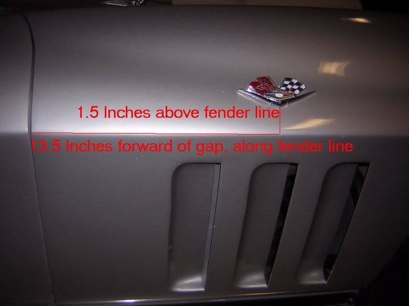
Mine are original to fender.
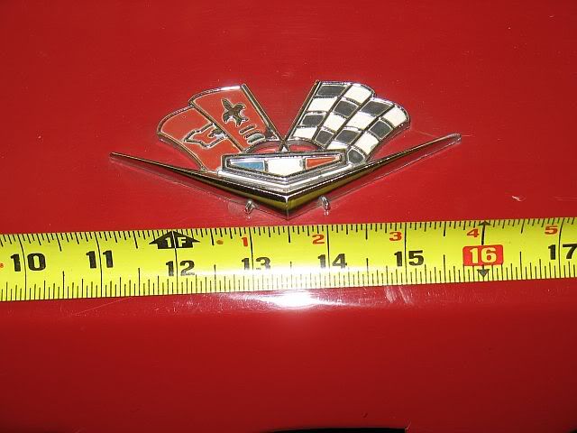
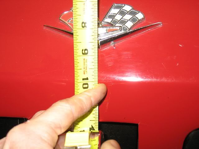
The horizontal measurements on mine are 13.5"
The vertical measurements on mine are 1.5"
jack
Mine are original to fender.
The horizontal measurements on mine are 13.5"
The vertical measurements on mine are 1.5"
jack
 01-09-2011, 06:33 PM
#4
Tech Contributor
 01-09-2011, 06:46 PM
#5
Team Owner

Member Since: Mar 2003
Location: Greenville, Indiana
Posts: 26,118
Received 1,843 Likes
on
1,398 Posts

'65-'66 are the same. Don't pattern a '63-'64 off these measurements.
 01-11-2011, 06:04 PM
#8
7th Gear
Thread Starter
Member Since: Jul 2009
Posts: 7
Likes: 0
Received 0 Likes
on
0 Posts
Thanks for the quick replies and the great information. I will get to body shop tomorrow if the snow storm does not keep us all in doors.
This was my first post and I'm impressed with the responses.
This was my first post and I'm impressed with the responses.
01-12-2011, 08:33 PM
#9
Safety Car

The Assembly Manual also shows the hole placement on UPC 11-13, A1 (not sure that is the proper drawing # - page E178 is handwritten at top of page - page shows LH 1/4 body view).
15/64" dia. (2) holes.
Also makes mention to cut off end of rear most stud on RH side only to clear heater installation.
The hole pattern is a bit hard to interpret, but it appears to indicate the following:
Hole c/c 2.04"
Front hole located 1.12" forward of body vertical reference line "O" (reference lines tied to another sheet in assembly manual).
Holes horizontally 0.88" above body horizontal reference line "20" (again reference tied to another sheet in assembly manual).
Last edited by bub; 01-12-2011 at 08:56 PM.
01-12-2011, 08:45 PM
#10
Safety Car
UPC 1 BOLT WELD REF. C4. C5. (again not sure that is the proper drawing # - page E46 handwritten at top of my version sheet [page shows LF fender door hinge and A pillar on coordinate grid]) had the body reference points.
The intersection of vertical reference line "O" and horizontal reference line "20" is above the horizontal body ridge ("Line B") at point 18 by 20" - 18.63" = 1.37".
Point 18 is on the horizontal body ridge line.
This puts the holes 1.37" + 0.88" above the horizontal ridge line = 2.25" (for the holes not the tip of the emblem )
This fixes the location in vertical space (assumes BB or SM pins are same pin drilling).
To fix it in horizontal space, we'll that's probably best with what the guys have noted above. My head hurts trying to decipher the AM document, probably had templates in the factory made once to the dimensions and repeated 20,000 times. Horizontal appears to be keyed off front of door edge point 16 which shows 13.5 inches from bottom tip of emblem near point 18 and 18.49" height from zero datum.
The 13.5 inches agrees nicely with the actual measurement above.
Last edited by bub; 01-13-2011 at 11:47 PM.
01-13-2011, 12:36 PM
#11
Team Owner


Member Since: Oct 2000
Location: Washington Michigan
Posts: 38,899
Received 1,857 Likes
on
1,100 Posts

All of the dimensions in the Assembly Manual are referenced to body inch lines in 3-dimensional space (the GM Body Dimensional Grid System); none are measured on the body surface, and none relate to any specific points on the body. Makes it interesting trying to correlate grid dimensions to a real car. 
01-13-2011, 11:32 PM
#12
Safety Car
All of the dimensions in the Assembly Manual are referenced to body inch lines in 3-dimensional space (the GM Body Dimensional Grid System); none are measured on the body surface, and none relate to any specific points on the body. Makes it interesting trying to correlate grid dimensions to a real car.

I believe that there is also a distance from longitudinal centerline (line of symmetry) listed on the grid system (C' LINE) that locates surface points in 3 dimensional space, similar to an x,y,z axis CNC machine.
The tables list the 3 dimensions as:
C' LINE (=z), "O" LINE F.O.D. {front of door?} (=x), and HEIGHT (=y).
e.g. Points 16 & 18 on LF fender as referenced above per the 3D locations are:
Point 16: C' LINE = 33.69", "O" LINE F.O.D. = 13.5", HEIGHT = 18.49"
Point 18: C' LINE = 34.28" (makes sense - Coke bottling to fender), "O" LINE F.O.D. = 0.00" (on 0 reference line), HEIGHT = 18.63" (beltline slightly higher vs. datum than at door).
That said, the hole dimensions referenced above should hold true when projected in 2D (side view only).
Check my math, but I'm still thinking that the emblems mounting holes are 2.25" above the horiz. beltline. If someone can confirm on a loose SB emblem that the pins are 3/4" above the bottom tip of the bottom of the SB emblem, that would validate the 2.25" above the beltline for the holes vs. the 1.5" for the tip as measured/depicted above.
Bottom line, I think this pic is accurate, and correlates with the AM info.:

Last edited by bub; 01-13-2011 at 11:53 PM.
01-14-2011, 01:32 PM
#13
Team Owner
Member Since: Oct 2000
Location: Washington Michigan
Posts: 38,899
Received 1,857 Likes
on
1,100 Posts