1962 340hp radiator seal kit?
 09-18-2011, 10:16 PM
#1
Advanced

Thread Starter


Trying to help with the Florida heat 327/340HP so I purchased a 3 piece lower seal and two side seals for my radiator but can't find any literature for installing these parts can anyone help? The side seals have holes in them but don't seem to line up with any of my bolts.
Scott
Scott
 09-18-2011, 10:21 PM
#2
Tech Contributor

The side seals attach to the side of the radiator core support, if I remember correctly.
The 3 other pieces glue to the bottom of the core support, like this:
The 3 other pieces glue to the bottom of the core support, like this:
09-18-2011, 10:38 PM
#4
Tech Contributor
09-19-2011, 09:30 AM
#5
Melting Slicks


Look in the options sections in the back of the AIM. There's a page there that shows how these seals go.
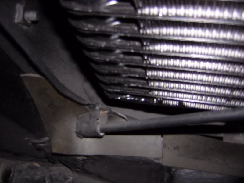
Consider stuffing split foam 1" pipe insulation down the sides of the radiator in the mount and across the top of the fan shroud. It's cheap and easily removable for judging.
Consider stuffing split foam 1" pipe insulation down the sides of the radiator in the mount and across the top of the fan shroud. It's cheap and easily removable for judging.
09-19-2011, 10:50 AM
#6
Instructor
Member Since: Jun 2006
Location: Houston TX
Posts: 223
Likes: 0
Received 0 Likes
on
0 Posts

Scott,
I have exactly what you need. Give me the day to dig up the reference materals. But I can tell you that the pieces are not glued they are connected with what are called robbins clips, which you can get from Paragon. I will post the reference materials for you.
I have exactly what you need. Give me the day to dig up the reference materals. But I can tell you that the pieces are not glued they are connected with what are called robbins clips, which you can get from Paragon. I will post the reference materials for you.
 04-29-2014, 01:03 PM
#8
Instructor
Member Since: Jan 2013
Location: Amelia Island Florida
Posts: 194
Likes: 0
Received 16 Likes
on
7 Posts
Great pic and Idea for the isulation. I am ready install my new radiator also and A/C. Do you have a completed engine bay pictures so I can see the Compressor and Alternator & overflow tank set up.. Thanks if you can...
 04-29-2014, 01:46 PM
#10
Team Owner


I got the idea from Bill but that round pipe insulation along the top and down vertically on both sides of that loosely designed C1 shroud really makes a difference!
05-01-2014, 07:21 AM
#11
Instructor
Member Since: Jan 2013
Location: Amelia Island Florida
Posts: 194
Likes: 0
Received 16 Likes
on
7 Posts
great pictures of the full engine bay. Two other questions, inotice the compressor is on the pass side and you relocated the alternator to the drivers side and then the aluminum tank to the pass side. What brackets did you use for the Alternator and the tank ? Thanks for the help....
05-01-2014, 09:07 AM
#12
Race Director

Member Since: Jun 2006
Location: Inverness FL
Posts: 17,891
Received 729 Likes
on
623 Posts
St. Jude Donor '07
great pictures of the full engine bay. Two other questions, inotice the compressor is on the pass side and you relocated the alternator to the drivers side and then the aluminum tank to the pass side. What brackets did you use for the Alternator and the tank ? Thanks for the help....
http://www.alangrovecomponents.com/S...Short_Pump.htm
for the tank i made a simple rectangular plate and spaced it out past the exhaust manifold (similar to the way the a/c mount is done) and then bolted the original tank mount to it.
Bill