When you click on links to various merchants on this site and make a purchase, this can result in this site earning a commission. Affiliate programs and affiliations include, but are not limited to, the eBay Partner Network.
283 CI Engine Build for Harmonic Balancer, Water Pump, Generator Pulleys & Brackets
I built a parts buck engine to show a stock 1959 to 1961 partial assembly to help clear up confusion about brackets and pulleys in the drive belt system. I will also show methods to help align the generator to the pulley system, as this design was not ideal and allows much movement during assembly and some critical areas that must be observed. There are many photos and measurements shown to help visualize assembly.
Any feedback, corrections, comments always welcome.
It will take some time to edit and add comments and captions, as I'm doing it on-the-fly.
Rich
Edit 12/30/14 - See end of this post for the attached PDF version of this document. Special thank you to DZVette (Dave Z) for creating and editing for me.
======
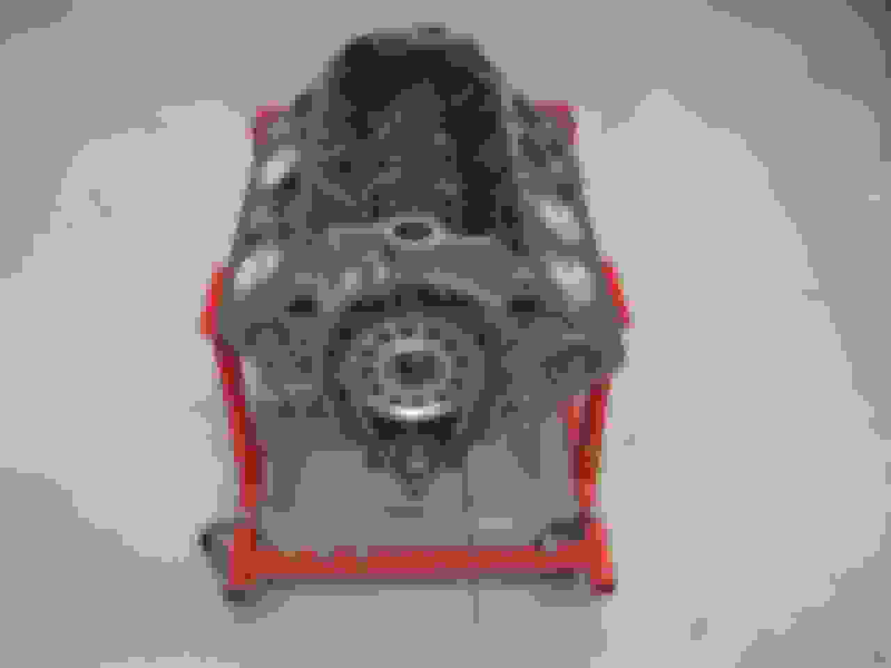
The Parts Buck Engine. A 1961 283 CI with stock build. This one is slated for Fuel Injection and has Domed Pistons, the Duntov Camshaft, and will have solid lifters. It included a Cloyes adjustable Timing Gear set to allow the cam to be dialed in. It was balanced by the shop, meaning all connecting rods and pistons were weighed and altered for equal weight.
After returning from the machine shop...
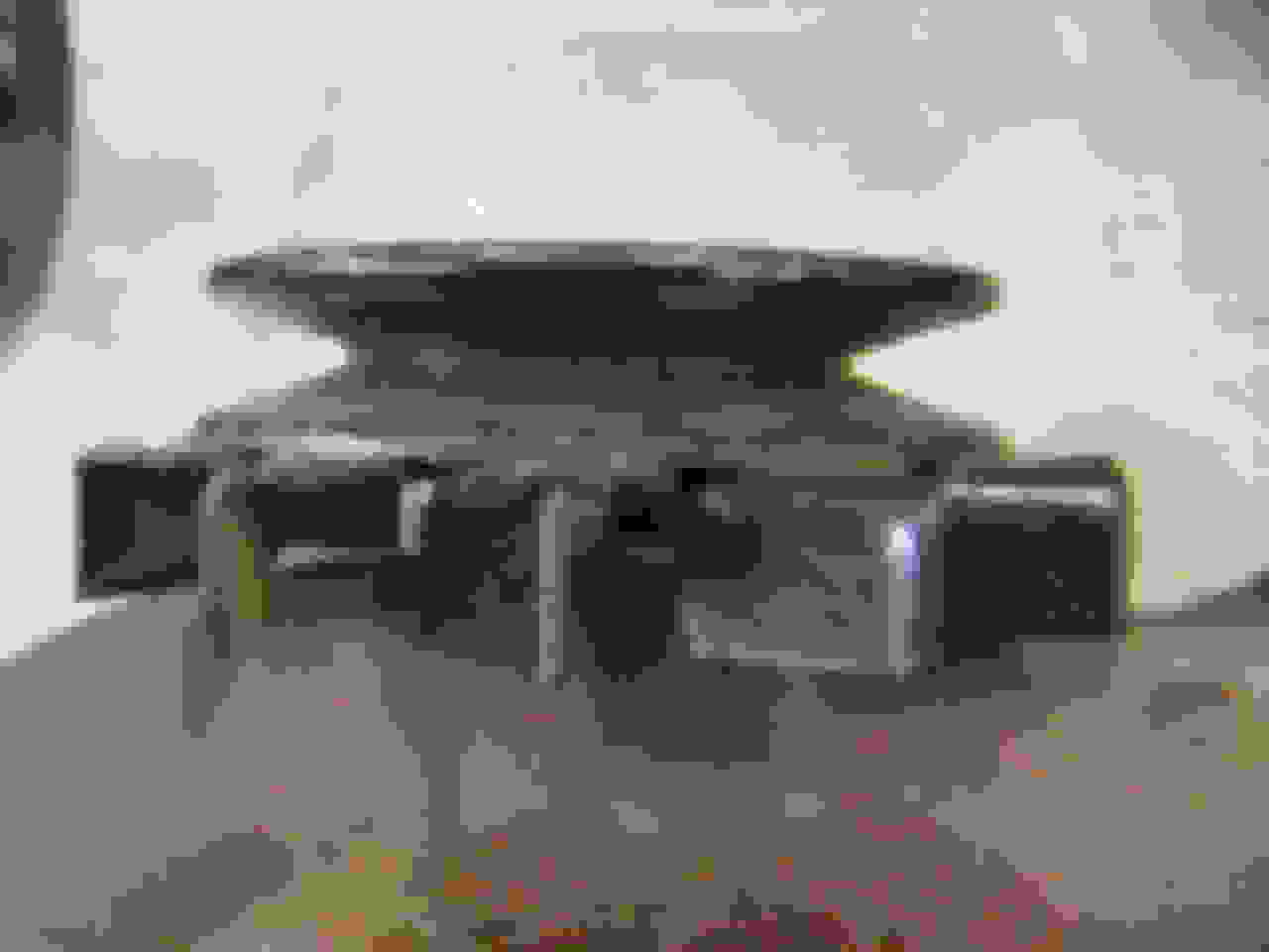
Here it is after trial fitting the heads and other various pieces for the trial build exercise.
Here is the crankshaft snout. Note there is no harmonic balancer(HB) spacer installed. This spacer will be discussed later.
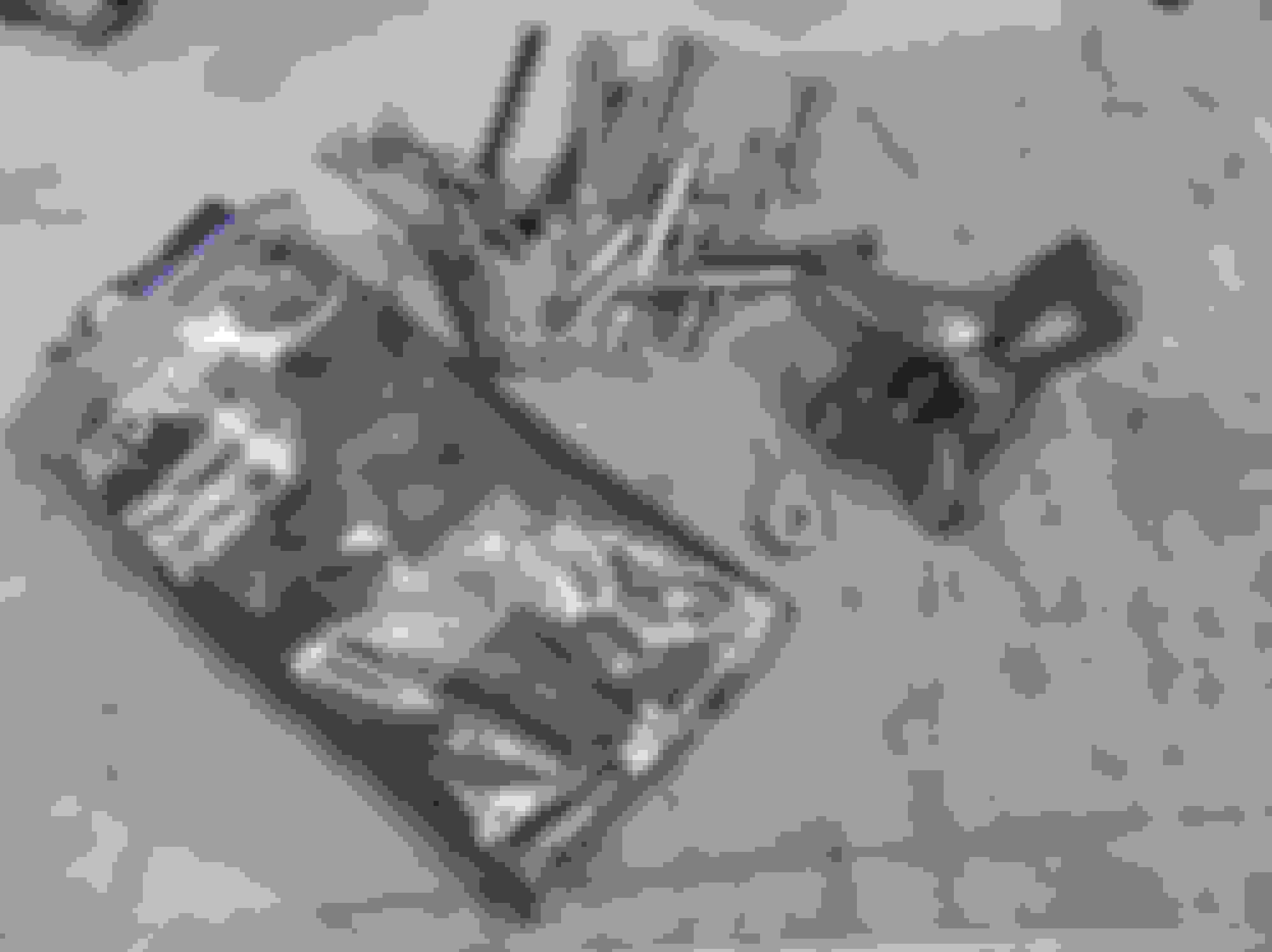
Here are the pieces to be installed. (with the exception of the timing chain cover so it will be easier to photograph and measure the items in the assembly)
The small round washer with the keyway slot is the HB spacer. On the 1956(some applications) to 1962 Corvette, this must be installed to allow the HB pulley to align with the stock Chevrolet Water Pump(WP). Because the front engine mount sits between the block and the pump, that same thickness must be matched at the balancer where it attaches to the crankshaft. This brings the HB pulley forward to match the WP.
One problem I had was that I did not have the stock '58-'61 generator U-Bracket, GM part# 3750548, used on 1958-1961 Non-FI engines. Its dimensions are 1 7/8" H x 6 5/8" OAL (overall length ). This engine is destined to be reassembled as a 315HP Fuelie for the '61 I'm restoring. My U-Bracket is slightly longer with offset mount holes for the 1102268 generator which has different mount spacing, 7 ". For the parts buck build I had to improvise. I used the longer U-Bracket designed for the 11022268 FI generator, not for the tach drive generator 1102043. I simply extended the rear of the generator case to the rear frame (Commutator End frame). I did this by adding spacer washers between the end frame and the rear of the generator case. This has no effect on pulley alignment as the front frame(Drive End frame) ends up in the same position as it normally would.
Also, the 1102043 generator I used in this buck was not the one pictured above. I had to use a Passenger car generator that i had on the shelf. This is only different in the distance of the armature shaft to end frame mount hole centers. It's 1/2" taller in it's mounted position. The only effect this has on the buck is that the belt tension will yield a slightly shorter profile. Since this exercise is to show alignment methods and assembly practices,this also has minimal affect on the main objective of this document.
I've included an Addendum (A) at the end of the document showing the different generator U-Brackets used for various years and horsepower applications.
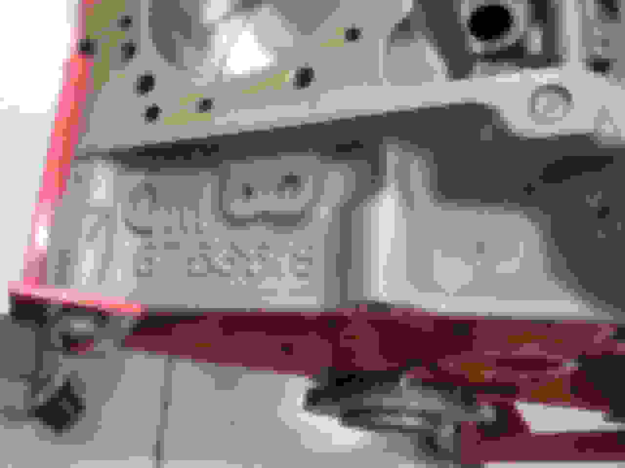
This is the exhaust manifold for the Right Side, GM part# cast 3750556. This is used on 1958 to 1961. It has 2 threaded 7/16 holes for the generator brackets. You can't see it here, but this one is for the FI application, as it is missing the machined holes for the carburetor choke fresh air tube. Other than that, it's the same manifold used on the non FI engines.
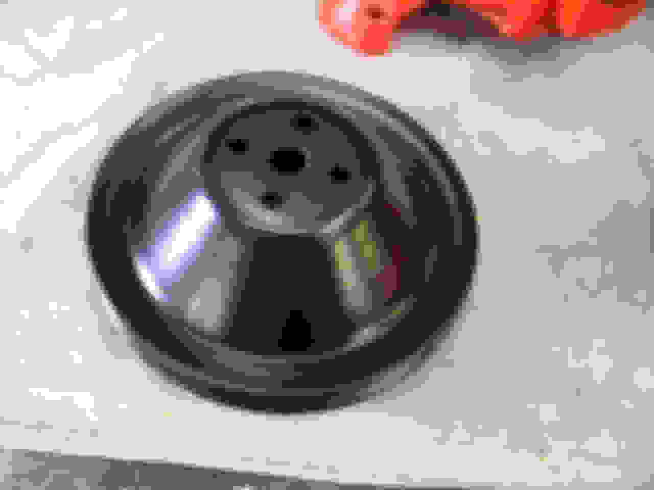
This is the Water Pump Pulley GM part# 3724816. Used on all engines from Late 1958(with hood support on the left), up to Early 1962. Early 1958 used a stepped pulley part# 3827846. Late 1962 used 3770245, 7 1/8" diameter double groove, IIRC for the SHP engines.. The double groove is to accomodate a idler pulley drivebelt.
This is the stock Harmonic Balancer pulley, GM part# 3756328. This was used on all 1958 to 1962 engines, except the 1962 Special High Performance(SHP) Fuel Injection. That option required GM part# 3858533 double groove pulley, 6 5/8' diameter. The double groove is to accommodate the idler pulley to the above mentioned 3770245 Water Pump pulley. Note that pulley was also used up to 1980 for various engine configurations.
A close up of the casting number 3750556 RH. This will be more visible when cleaned and painted for the actual engine build.
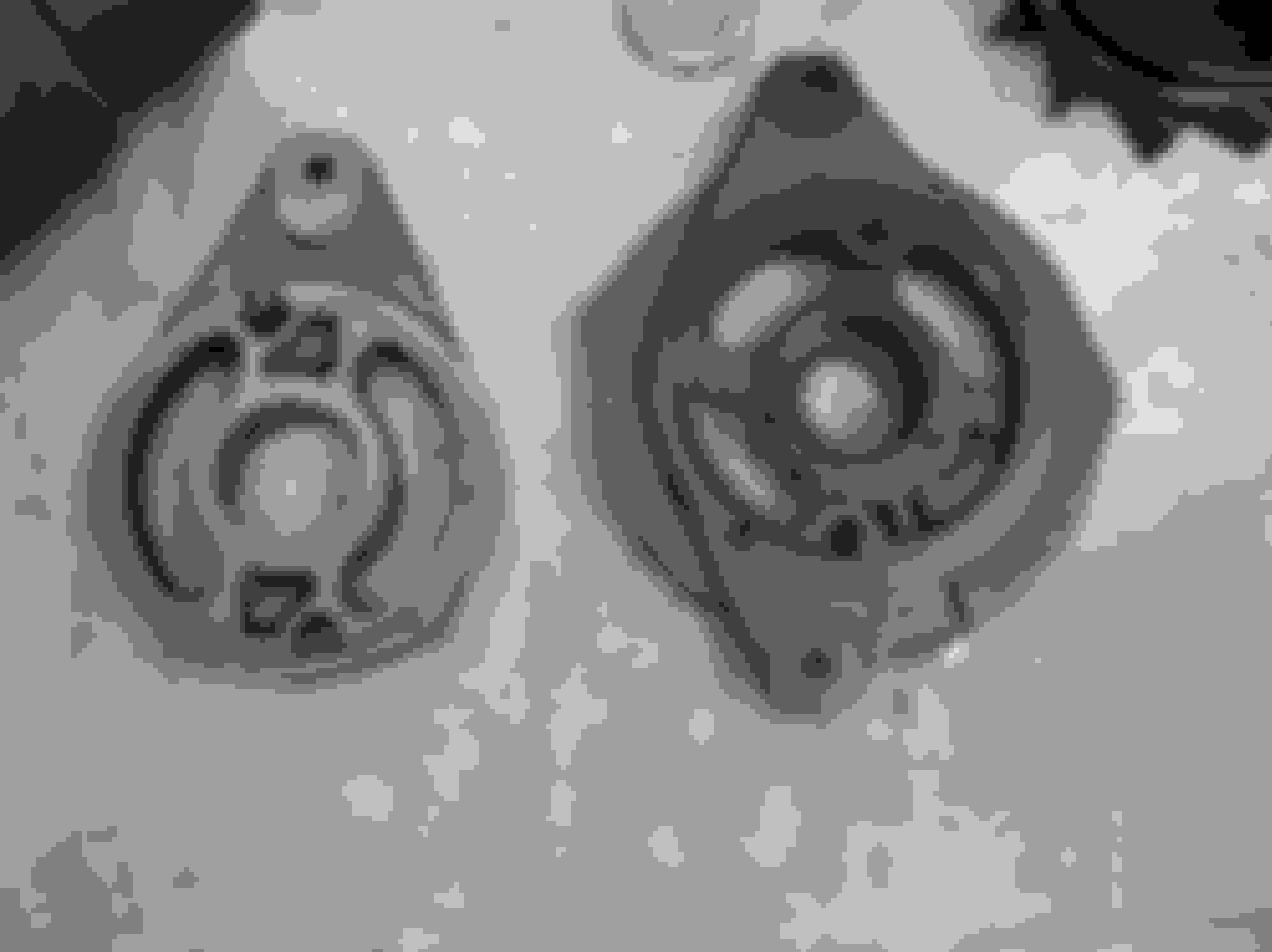
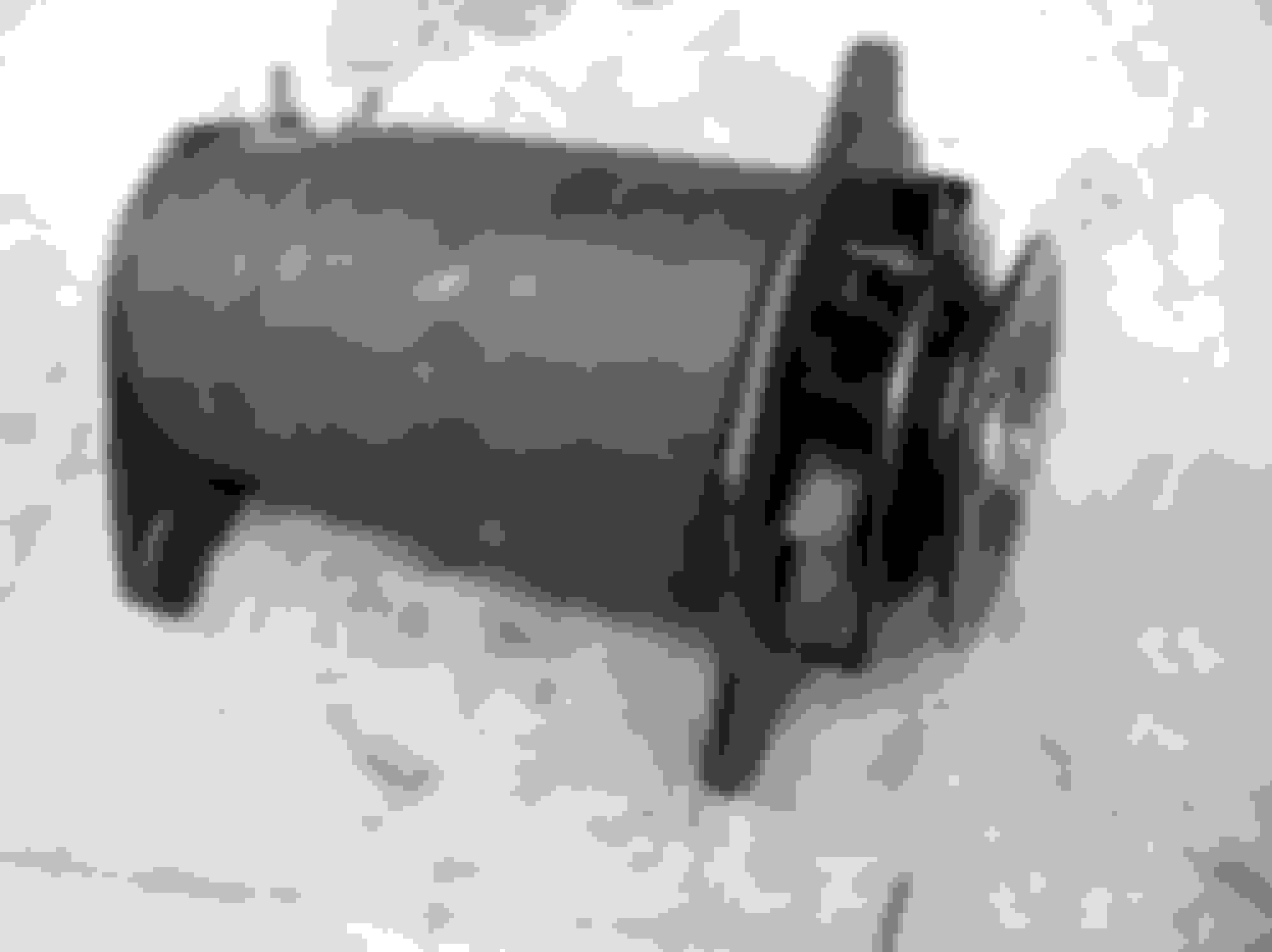
The generator is a stock issue 1102043 NON-FI unit. This was used from 1956 to 1961, but has variations of attaching parts and pulley usage based on year.
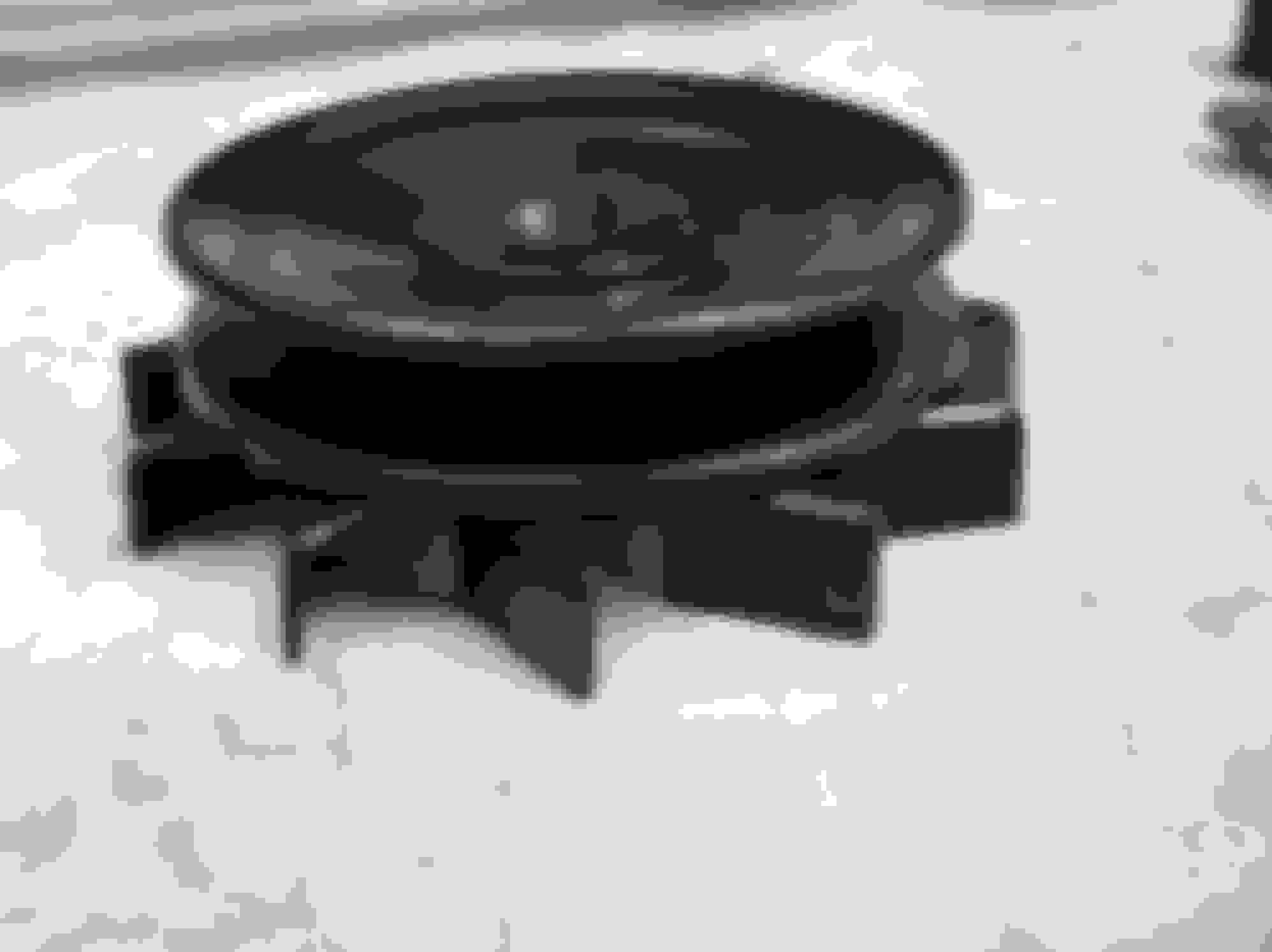
The 1958 - 1962 generators used a special 3 5/8" pulley which has a 1/4" offset/space between the fan and backside of the pulley dish.
1956 - 1957 used a 3 5/8" pulley also, but no offset/space.
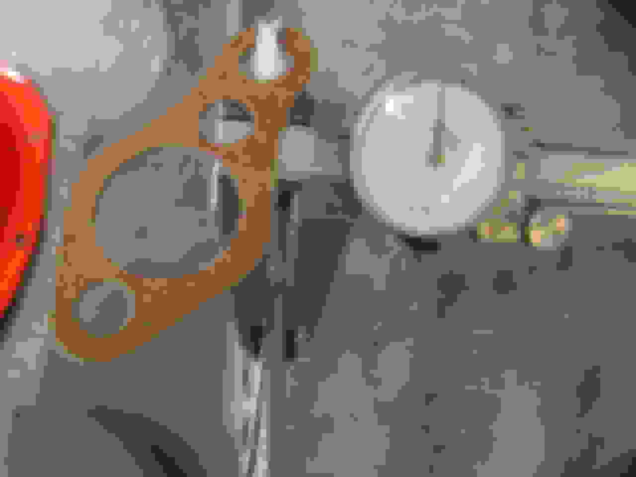
This shows the thickness of the engine bracket......apx 0.150".
This shows the thickness of the engine bracket......apx 0.180" including one additional water pump gasket.
This is the Water Pump Pulley Reinforcement. GM part# 3720616. Pictured is a reproduction.
This shows the thickness of the Harmonic Balancer Spacer......apx 0.150"
The WP pulley reinforcement is apx 0.042" thick at its mount surface.
Here shows the height of the Harmonic Balancer, apx 2 1/16" to the face of the outer ring.
The inner sleeve of the balancer snout measures apx 2.330".
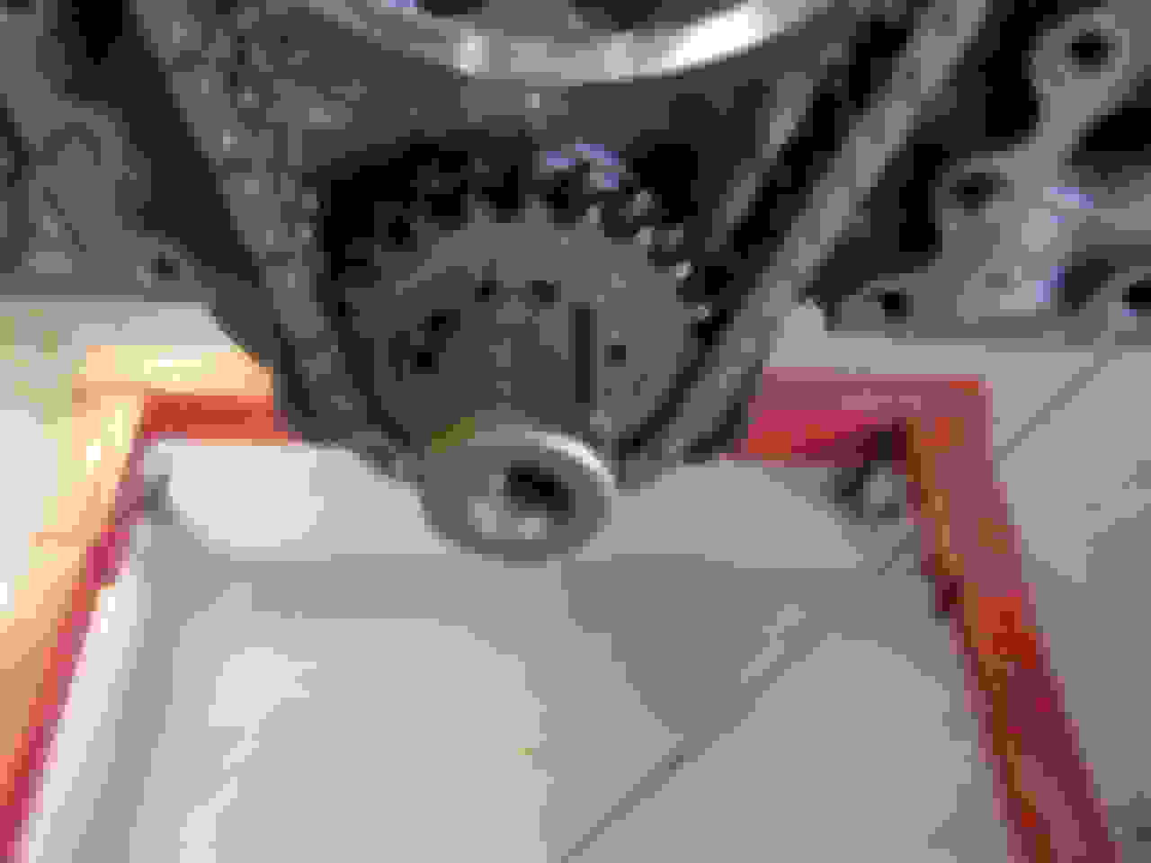
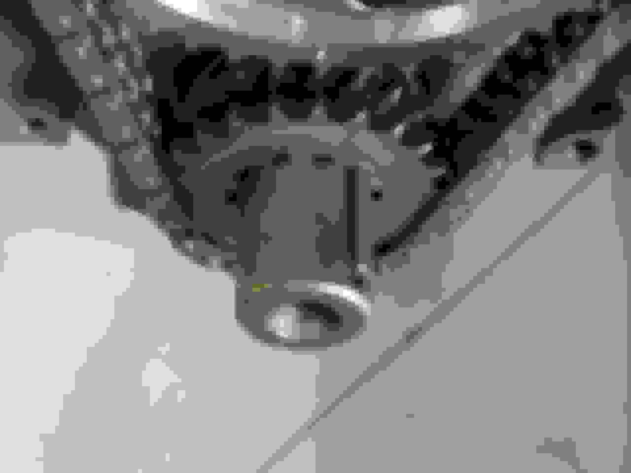
Here is the crankshaft before installation of the HB Spacer.
It measures apx 1.330" from the face of the crankshaft timing gear to the front edge of the crank snout.
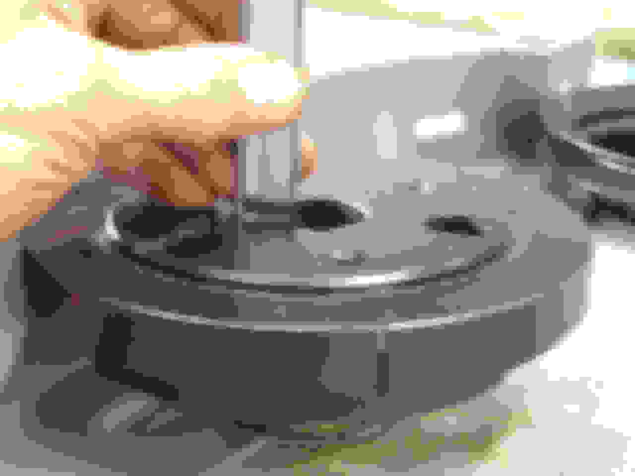
Here I install the HB spacer. This must be installed before the balancer is installed.
Here I measure the snout for reference after installing the spacer.
2.335"(HB Height) - (1.330"(Snout) + 0.150"(HB Spacer Thickness)) = 1.155" (I'm off a few thousanths in the numbers, hardly a factor)
When installed, the measurement from HB spacer to snout face is now apx 1.165". You can use our found measurements before and after HB installation to verify if a HB spacer is installed in a unknown engine assembly. This is particularly important, as you don't want TWO HB spacers installed, and find out later when things don't fit, or worse, the HB gets launched at high RPM's in the future.
A standard Chevrolet water pump measures apx 5.700" from the mount flanges to the top surface of the pulley hub. This is often a factor when buying a rebuilt pump, or one that someone has modified. Don't rely on "out-of-the-box" correctness. Measure it to be sure.
Measured again, the depth of the HB from the end of the mount hub to the front edge of the pulley hub is 2.335".
Here you can see the HB against the spacer. It was drawn in tightly.
Here is the end of the crankshaft through the hole in th HB. It measures 1.150" from crank snout face to edge of HB.
Here I've mounted the Water Pump using a gasket on each side of the engine brace. Note the 3/8" special stud for the generator brace. I've also mounted the pulley to the HB.
Here is the WP reinforcement mounted on the WP hub before the WP pulley is installed. This item should always be used as pulley condition and life will be extended.
As you will see, there is a mismatch of the HB pulley to the WP pulley. It's off by about 1/8". Why is this? Variations in pulleys, water pumps and their hubs, and varying gasket thickness can play a role in these tolerances. But there are ways to correct these anomalies.
Here I have added one additional WP pulley reinforcement to help get better pulley alignment. This may not have been done at original build, as it's costly for many cars, but in your case it may make your build easier and a better finished product.
Now it's closer.
Another alternative to alignment is more involved. The Water Pump Hub can be adjusted to match, or can be adjusted to correct rebuild shop errors when it was installed. In this case, the hub could be "Pulled" forward using a 3-jaw puller to make up the difference. Do this very slowly and carefully, as you do not want to pull it too far out. Small steps and measure carefully between steps.
If the hub needs to go rearward, the pump MUST be removed from the engine and partially dismantled. After the WP rear cover is removed, a press will be needed to push the hub downward the required amount. A small diameter socket is held against the rear of the shaft where the impeller sits, to ensure that the impeller location is not altered on the shaft.
Here is the exhaust manifold boss to attach the generator brackets. Make sure the threads are clean by using a thread restoration die. It has a bottoming end to allow you to get very deep into the threads.
Here the main offset brace support, GM part# 3755555 is installed directly to the manifold. Ensure that the upper tip is pointing forward. If not, the generator will not reach the desired drive belt plane.
Then a U-Bracket, GM part# 3750548 is installed to the previous bracket, then the generator is mounted to the U-Bracket.
This is where you must make unconventional "adjustments" to the brackets and generator to achieve optimum alignment.
Here is the generator using the correct offset pulley again. It's off apx 1/8" forward, measured using a straightedge as shown below. You can see the alignment error in the photo by looking at the belt as it exits the top of the generator pulley.
Note the rubber bushings on the lower mounts. One side has a flat outer ring. Placement direction of these in the generator end frames can help offset small variances in the alignmnet. The pointer shows a ridge on one side of each bushing. Replacements do not always have this feature. Because of this, the generator can move forward or rearward when tightening the adjustment brace while pulling the drive belt tight.
I check HB to WP pulley alignment to verify it's correct.
Here I've placed the straightedge against the generator pulley to see the alignment error at the WP pulley.
It's off apx 1/8".
Here I've installed the NO-offset generator pulley as a experiment. It now shifts the alignment error rearward.
Apx 3/16" error rearward using the NO-offset pulley.
Here are the generator bushings to show their profile.
I've reversed them in the end frames.
And remounted the generator.
Checking alignment again.
It's still too far rearward. This pulley will not work.
I reinstalled the offset pulley. With the rubber bushings reversed, the alignment is closer to the WP pulley.
However, when the straightedge is placed between the HB pulley and generator pulley, a small error persists, this time forward.......
....as shown here.
Then by loosening the generator U-Bracket, and manifold bracket, as there is a small amount of play in the holes of those mounts, I was able to align the generator even closer to both pulleys.
The idea here is to to sometimes "cheat" a bit here or there to get proper pulley alignment, after all of the correct bracket and pulley hardware is installed. The Harmonic Balancer spacer MUST be installed as a baseline for ALL other alignments. The Water Pump Hub must be properly installed and spaced on it's shaft for proper alignment. The generator pulley MUST be the correct offset type for proper alignment.
Once all of the correct pulleys and brackets are installed, slight adjustments can be made at other mount points to get the ideal pulley and drive belt alignment.
Here are a few additional measurements for reference......
Face of engine mount brace to Water Pump Pulley.
Face of block(adjacent to Timing Cover) to HB ring and HB pulley.
Addendum A - Generator U-Brackets
===========================
There a 4 different U-Brackets based on application. I will show all 4 with dimensions here.
GM part# 3728514 1956-1957 Non-FI
1 11/16"H x 6 7/64"OAL
GM part# 3750548 1958-1961 Non-FI
1 7/8"H x 6 5/8"OAL
GM part# 3750876 1958-1959 With FI & High Lift Camshaft
1 5/8"H x 7 1/8"OAL
GM part# 3768152 1958-1962 With FI (Hydraulic and? H/L Camshaft) ?? unsure
1 5/8"H x 7 1/8"OAL
Addendum B - Fuel Injection Applications
==============================
Here I've removed the 1102043 30 amp generator and have set up the 1102268 35 amp generator for trial fitting on this 1961 engine. This 2nd design generator is used on High Lift camshaft solid lifter engines. The 1st design generator is 1102173. It has a different drive end frame. 1958 to 1960 FI generators vary in their part number and configurations. Since this is a 315HP engine, I will concentrate on this only, but the principles of assembly and alignment will be similar.
This 1102268 generator is unique as it has no tachometer drive, a large bearing cap on the commutator end frame, and both end frames contain solid mounts with no rubber bushing. It requires a different U-Bracket mount, the 3768152, which is spec'd at 1 5/8"H x 7 1/8"OALwith offset mount holes.
Here is the generator in pieces before I did a trial reassembly. Note that it's spacing between the armature shaft and mount holes is 3 1/2". Non FI generators with tach drive are spaced 3 1/4". This can get confusing, as the Passenger car and Truck base generators are spaced at 3 1/2", as the 1102268 generator is.
The pulley for this application is 4" diameter, with NO offset. Also Deep Groove
This is the FI manifold, note without access hole for a fresh air carburetor choke tube.
Here the generator is mounted showing the U-Bracket. Note the solid mounts.
When first attached, alignment was off about 1/8"....
....as seen more closely here.
By loosening all bracket bolts, as well as the exhaust manifold bolts, and then pulling everything more forward before re-tightening, I'm able to bring the alignment in to near perfect.
Here is the result of making minor adjustment to all generator mount points.
This is proper generator alignment.
Addendum C - Removing and Installing the Harmonic balancer
======================================== =====
Harmonic Balancer Removal
With threaded crankshaft:
-------------------------
It is best not to install the HB using the attach bolt. This is a 7/16' x 20 2 1/4" bolt, Grade 8, with special thick washer and lock washer. It should be torqued to 60 lbs/ft after it is installed.
To install the HB use a puller. If not available, acquire a threaded Grade 5 bolt 7/16 x 20 about 3" long, cut the head off, then using a die, thread it to the appropriate size at the cutoff end. You can use coarse thread there.
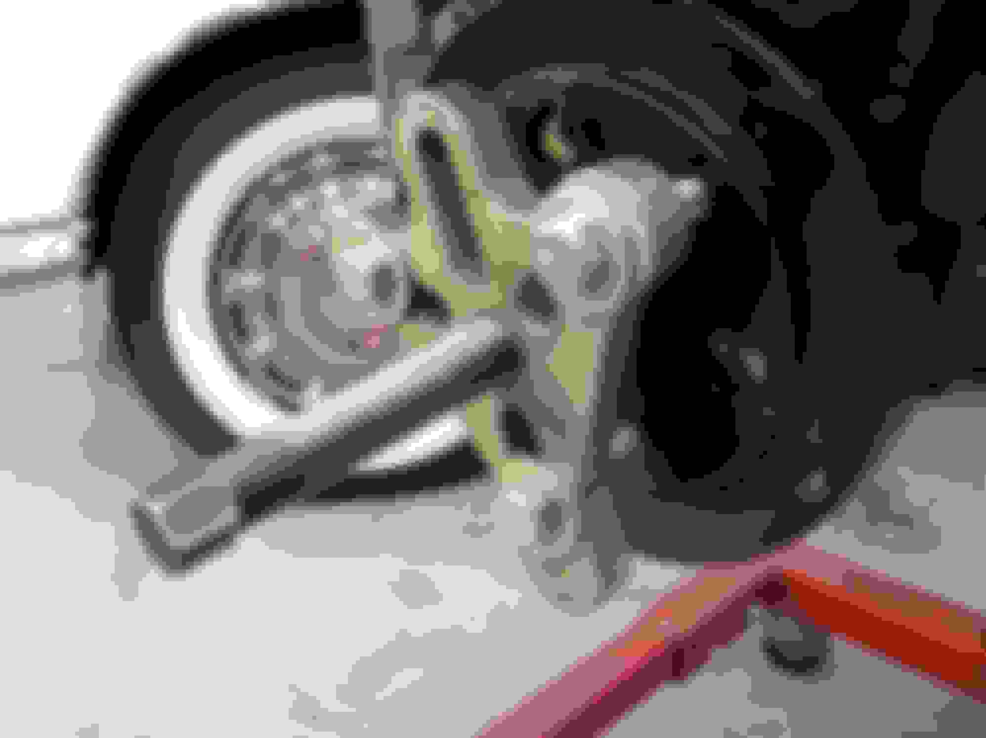
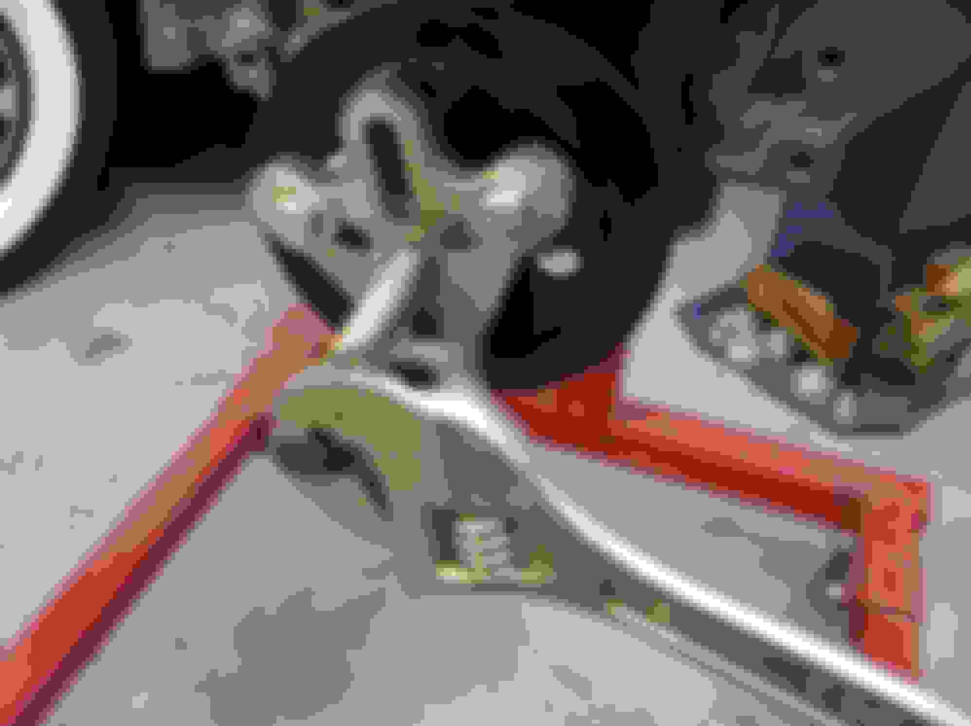
These are my home-made "Pullers". Simply thread the stud into the crankshaft until seated, install the HB and using a nut on the forward end, pull the HB over the crank. The large one is 7/16" x20 & 7/16" x 14 on the "nutted" end. The smaller one i had to make for a different car which had 3/8" threads in the crankshaft and a safety-wired wired bolt on a '56 race-car.
To remove your puller you may need to double nut it and remove it by turning the inner nut CCW.
Without threaded crankshaft:
----------------------------
My process to install a HB is what is described in period GM Service Manuals, but along with some additional methods. The books say something like this...."Using a wood block, drive it on with a hammer until home."
If the engine is out of the car, I position the rear of the engine against a solid wall or beam. This helps absorb the shock of the hammering. After installing the HB spacer I start to push the balancer, with keyway aligned to key, onto the crankshaft as far as possible. I mount my HB Puller frame tightly against the HB face, flat side to the HB face. Using a solid block of oak hardwood and a 3-4 lb hammer, I simply drive it on hitting the block with a hammer until it's home.
If the engine is in the car and you have limited space, just use whatever can reach in that tight space. Sometimes you have to pull the radiator and fan shroud to get enough room. You obviously cannot back-up the end of the crankshaft so use caution and solid hammer action.
Harmonic Balancer Removal:
To remove the balancer use a HB Puller. This one can also be used as a steering wheel puller.
End.
Last edited by rich5962; 12-30-2014 at 03:30 PM.
Reason: added more info and addendum B & C
I just find it amazing how dedicated you are to helping people. The amount of work doing all this and putting it together and asking nothing in return speaks volumes of your character.
Thanks Rich for showing how you measure everything. This will help me a lot when I get my engine back from the re-builder as I am going to install a left side alternator and will use your techniques to line up my pulleys. I believe that my spacer was missing when I pulled the HB off as I don't remember seeing it. I will check tomorrow.l
I noticed your crank has a threaded hole for a HB bolt but mine does not. Why is that? It is a 1960 block. (casting date). Should it be drilled? Should I get it drilled?
I just find it amazing how dedicated you are to helping people. The amount of work doing all this and putting it together and asking nothing in return speaks volumes of your character.
Glad it may help Dennis, and others too. I had the day off today but I had all of the stuff sitting there, a gorgeous day with the doors open, so I had some fun.
Thanks!
Originally Posted by stvaughn
Thanks Rich for showing how you measure everything. This will help me a lot when I get my engine back from the re-builder as I am going to install a left side alternator and will use your techniques to line up my pulleys. I believe that my spacer was missing when I pulled the HB off as I don't remember seeing it. I will check tomorrow.l
I noticed your crank has a threaded hole for a HB bolt but mine does not. Why is that? It is a 1960 block. (casting date). Should it be drilled? Should I get it drilled?
Thanks, Steve
Steve, Original crankshafts did not have the drilled and tapped threads until the High Performance engine in the mid 60's IIRC. Your '60 engine did not have it drilled and tapped originally.
This is a '61 block, and because I'm using a used rare original HP harmonic balancer, I told my machinist to drill and tap for the 7/16" x 20 bolt. Strictly a added safety, that's all.
If you're using a new balancer, that's fine, they just get hammered on with a wood block against the face while whacking with a 3lb hammer. When I do that on a engine on a stand, I like to roll the engine against a steel beam or concrete wall so the shock is directed down the crank, not the thrust points.
If you're using your original balancer, check for wear inside the throat. You can have the machinist thread the crankshaft for the future if you ever decide to use the bolt. If being judged however....it'll be a small deduct.
I had a not so fun harmonic balancer issue once on my '59. I'll try to find the old thread to link it here.
Here's a excerpt from it....
It happened to me back in '87 on my '59 270hp. Doing about 60 on the highway though. I heard a big bang and then saw this orange and black round thing in my rear view mirror and then passed me in the left lane. Found it in the median in the tall grass about a 1/2 hour later. Flatbed got me home. I purchased a OTC GM replacement balancer right away. 8 years later had the crank drilled and tapped for the bolt during a engine rebuild.
I'll never forget that night. Was a gorgeous summer Friday. I decided to take the '59 to work that morning. I called my wife later and asked if she wanted to go to dinner out that night, she jumped on that idea and lined up a sitter for the 3 boys, 5, 7 and 9 years old. They loved the babysitter, such a nice and cute kid from the neighborhood.
I was all excited about taking my sweetheart wife out in my sweetheart ride that night. When I left work I took the back roads home, then got on the highway for the last few miles. I was going down the on-ramp, just casually shifting and cruising on to the highway. No cars nearby and was just getting to about 55-60 when it happened. Scared the heck outa' me.
About 10 or so cars stopped by in front of me in the breakdown lane asking if I needed help. One of them went ahead and called my wife for me, with a message to come down to the Chelmsford exit to meet up, and to call a flatbed to meet me there.
About a hour later, she and the 3 boys showed up in the Bronco, just about when the flatbed arrived.
The car went on the truck, with me riding shotgun while the wife and boys drove behind us in the Bronco. We got home around 7pm IIRC, all of us exhausted from the ordeal. We ordered takeout pizza, got a kiddie videotape movie and called it a night. I was bummed.
Thanks for relating that story Rich. Don't want that to happen to me so I called my re-builder and asked him about the crank and he said he "always" threads the old cranks 7/16-20. Problem solved.
Rich;
Very nice and thorough writeup with great pictures.
I just wanted to offer a caution for those who have a drilled crank snout. Don't use a bolt to pull in the damper as there is danger of stripping the threads. Use a damper installation tool which has a long threaded stud that you screw into the snout all the way and then a spacer, ball thrust bearing and nut to pull in the damper. I just helped a friend last week that had used a bolt and stripped the crank snout threads trying to pull in and fully seat the damper. Fortunately the hole was deep enough and there were still some good threads in there so I was able to use my proper installation tool to pull it home for him. We did have to use a longer than standard grade 8 bolt and were able to torque it to the proper 60 ft lbs to secure the damper.
Rich;
Very nice and thorough writeup with great pictures.
I just wanted to offer a caution for those who have a drilled crank snout. Don't use a bolt to pull in the damper as there is danger of stripping the threads. Use a damper installation tool which has a long threaded stud that you screw into the snout all the way and then a spacer, ball thrust bearing and nut to pull in the damper.
PS. Nice looking shop!
Thanks K2, I was wondering what the proper method should be.
Thanks guys, glad it can help. I still need to add the addendum about the brackets, and believe it or not, a few more pics of the "tweaking' areas.
I'd also like to show some of the HB differences, as some pasenger car and Trucks have longer hubs and overall heights than others I believe. This may throw some assemblers off. If anyone has some measurement info related to that I'd like to add that in there too.
Originally Posted by K2
Rich;
Very nice and thorough writeup with great pictures.
I just wanted to offer a caution for those who have a drilled crank snout. Don't use a bolt to pull in the damper as there is danger of stripping the threads. Use a damper installation tool which has a long threaded stud that you screw into the snout all the way and then a spacer, ball thrust bearing and nut to pull in the damper. I just helped a friend last week that had used a bolt and stripped the crank snout threads trying to pull in and fully seat the damper. Fortunately the hole was deep enough and there were still some good threads in there so I was able to use my proper installation tool to pull it home for him. We did have to use a longer than standard grade 8 bolt and were able to torque it to the proper 60 ft lbs to secure the damper.
PS. Nice looking shop!
Yes I didn't mention the stud installation method, which I used to attach the one above. I spoke with Dennis over the phone about using that on his HB versus the attach bolt as it can gall the threads of the crank. Good reminder, I'll add that to the doc.
As you will see, there is a mismatch of the HB pulley to the WP pulley. It's off by about 1/8".
Rich:
Your crank pulley is about 0.125 inch further forward than your water pump pulley. This is after you installed a 0.120 spacer behind the damper. If you removed the spacer, you would be off by 0.005?
Example #2 from Dennis:
[QUOTE=jusplainwacky;1588371976 In the meantime there is something that is perplexing Rich and myself...and it appears that I do not have the spacer on the crankshaft that moves the harmonic balance out, yet my harmonic balance is lined up with the water pump pulley. I do not know if perhaps it can go on any further, but I have the bolt in the front and it is tight.
Now the question is...how is everything lining up if I don't have the spacer?? Perhaps if someone can tell me how far the harmonic balance is from the timing chair cover, that might give me something to check.[/QUOTE]
Example #3: my '59
My damper measures 2.32; yours measures 2.33
My water pump measures 5.69; yours measures 5.70
I have the same pulleys as you do.
My crank does not have a HB spacer.
My crank and water pump pulleys line up almost perfectly.
Sure looks to me like the newer pulley system was designed to eliminate the HB spacer.
Bill, I've always been under the understanding that all 1957 to 1962 and 56 2x4 Corvette engines require the HB spacer. This is due to the front engine brace thickness, and therefore to allow use of stock Chevrolet water pumps and balancers. I believe this was designed to bring those forward to match.
Without the spacer, the balancer would be too far rearward to align with the water pump pulley. The pulleys are different from Passenger car and truck due to deep groove design. I believe their heights may be identical in most cases.
For reference the P & A Catalogs specify....
56 w/ dual 4BC
57-62 3734984 SPACER, balancer ( 1 3/4" OD x 1 1/4 ID )
When the engine brace went away in 63, so did the spacer.
IMO, somehow on Dennis's, either the water pump hub is not to spec, or some oddity exists with the balancer, the crankshaft or keyway or the pulleys.
On yours, are you positive the spacer is not installed? Is your HB installed? If not, can you measure the crank snout face to the timing gear?
If you get apx 1.3", no spacer is installed, if you get 1.15", it is there.
My crank is out of the engine so I can see it clearly, but I do measure 1.3.....
Bill, when it was together and lined up, it was likely because all of the brackets and exhaust manifold were "cheated" into position, and/or your WP pulley hub was out of spec to get it aligned.
See my Post#1 Addendum C. After loosening all brackets, and the exhaust manifold, I was able to align the FI generator perfectly. This after being offset apx 1/8"+ at the pulley.
New edits in the Post#1 document were added this morning to include HB pullers and HB installation methods, and the mock-up assembly of the solid mount fuelie generator using different brackets, 4" non-offset pulley, and how I resolved alignment issues.
This is fantastic. Thanks so much for sharing this with us. I am putting a new water pump in my 60 and just pulled the exhaust manifolds off to paint them. So all your information about pulley alignment will be most helpful. You're awesome!!!! Happy New Year, Rick.
This is fantastic. Thanks so much for sharing this with us. I am putting a new water pump in my 60 and just pulled the exhaust manifolds off to paint them. So all your information about pulley alignment will be most helpful. You're awesome!!!! Happy New Year, Rick.
Glad it can help you Rick........ and Thanks.
Dave Z (DZVette) just sent me a updated PDF version which I just uploaded in the first post. It was mainly to correct some of my grammmmar and spullign mistakes.
 11-30-2014, 08:22 PM


 I'll try to find the old thread to link it here.


 , a few more pics of the "tweaking' areas.