When you click on links to various merchants on this site and make a purchase, this can result in this site earning a commission. Affiliate programs and affiliations include, but are not limited to, the eBay Partner Network.
Remember the valve covers that came on my motor? (They are pictured below) Aluminum valve covers with vinyl "CHEVROLET" emblems on them. I was afraid that the vinyl would end up looking like a "Shrinky Dink" on the valve covers after the engine ran for a while. Plus I just did not really like the way it looked. I have been looking for a way to dress these up a little.
I started by peeling off the vinyl and then took them to be polished. There is a guy out side of town where I live that polishes metal for a living. $40 later and they look almost like chrome.
Next I was looking for something different to spice them up. I was looking for some type of metal emblem or logo. Something I could bolt on. I also considered engraving. Then I ran across some replacement "FUEL INJECTION" fender emblems for a 1965 corvette. "PERFECT !! "
The engine is going to be fuel injected and these will look really nice. I am a little concerned about the maintenance of the aluminum. If it becomes too much to keep them looking good I may powder coat them later.
Well, I spent all day yesterday and this morning at the machine shop. I made some progress on my suspension parts but not done yet. My engine guy is cleaning up the block and getting ready to install cam bearings. The crank needed to go out for balancing.
So I can update you on a little project I started I think last winter.
I was trying to decide on seats for the car. I don't like the originals. They have very low backs and I would rather have a taller back and something with power adjust. I looked at other corvette seats and after market seats. In the end I decided to rob the seats out of my 1969 corvette. I will either replace those later or go with something else.
The 1969 seats are not power though. Again, I looked at after market stuff, used corvette stuff, and believe it or not I ended up buying a pair of 6 way power seat bases out of a Volvo for $130. Yep, and the driver side has the memory module so that two drivers can be programmed. They are narrow assemblies and would fit the seats perfect. All I need to do is make a couple of brackets.
I stripped down the drivers seat. The frames are solid. They will need new springs, foam, and covers. I will probably try to do something a little custom to the cover. Both seat bases seemed to be bent a little. The channel that forms the base looked like the inside was bent in with a hammer. Both seats, and the same place. Maybe the factory did that?? Can't figure out why they are that way so I straightened this seat out.
Next I disassembled the drivers side power seat base. I want to clean these up and re-paint some of it. With it apart I can use the seat mounting bracket from the power seat base to make brackets to mount it to the 1969 seat base.
I got that done and mounted that seat to the other power seat base (Passenger) since they are the same. I hooked up some temporary power to make sure everything works. There is a lot of forward and backward movement and more than enough up and down for a corvette.
Next I will take everything back apart to clean, sandblast, and paint if needed. Then re-assemble and do the same to the other seat. After that I will need to redo the seat mounting in the car. These are obviously going to bolt in differently.
Original 1969 corvette seat. This is the condition of both seats.
This is where the seat base was bent out. Not sure why, but both are like this.
Here I have made brackets and new attachment points for the power seat base.
Here the seat frame is attached to the power seat base. Everything works
Here more material is being removed before I profile the shape. Both parts currently look like the part on the left. Next I will set them up in a CNC mill to machine the final profile and radii.
Hopefully I have the finished parts in a week or two. I really need these to make any progress on the rear suspension.[/QUOTE]
I love seeing a fellow machinist using his skills on the forum!
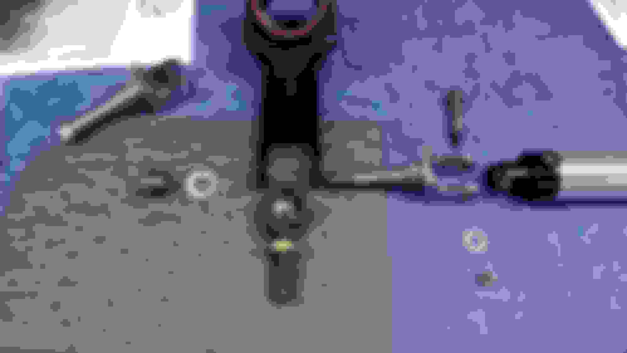
O.K., I got them done over the weekend. Finally, finally, finally I am really happy with how they turned out, but man, that was a lot of machining. Below is a picture of how everything goes together. I will be working on assembling the rear spindle supports and mocking everything up. Before I do the final assembly of the rear suspension I will have the new parts coated with black oxide. I don't want to paint them and powder coating adds too much thickness.
Above you see a spindle support. The rod end goes to my strut rod. The new lower shock mount goes through the spindle support and rod end. The other end of the shock mount, mounts the shock.
You might have noticed from my last post the aluminum shock. I had (still do have) a pair of Bilstein shocks for the rear which are a heavier duty version of stock shocks. I noticed that when they were mounted the rubber bushings were at a bind. As a matter of fact, they were very difficult to mount because of that misalignment. I started looking for shocks that had spherical bearings at the ends to give some alignment relief. Someone must make some, and yep, there are bunches out there. I found these made by "QA1". They have the same stroke as the stock shocks but were a tad longer with the compressed length. If you look at my new rear lower shock mounts you will notice that I have lowered the lower mounting bolt to compensate for the longer length. The suspension will bottom out on the frame before the shock bottoms out. These also have adjustable rebound for tuning the rear suspension. They should be a nicer shock for the rear and with the spherical joints at the ends give flexibility with the mounting points.
I have been working on a lot of some what little projects this week. I have also spent a little time at the machine shop working on something new that I think will work. I will talk about that later.
One of the items that I did get complete this week is assembling the rear parking brakes. This is part of my preparations for assembling the rear trailing arms. The brake shoes that I removed from the car at the start were brand new so I reused those. The springs were new, but everything else was old and rusty so I ended up buying a new hardware kit. The back plates are the originals that I had sand blasted and powder coated.
Luckily I took pictures when I dis-assembled them. That reference picture made assembly real easy.
Last January I was looking at my rear upper shock mounts. I was considering moving them to the inside of the frame rather than below the frame. The reason why was to gain more clearance between the shock and my offset trailing arm. I decided to go ahead with that move. I still used the original bracket. I made a new bracket that utilizes the original bracket and helps support the shock on the inside. After the brackets were made and fitted I had them anodized black.
The machined brackets. I used a long shoulder bolt to go through the original bracket and the new bracket. This is a 1/2" shoulder bolt which is a nice slip fit for the spherical joints on the shocks. Once all the way through both brackets the shoulder bolt threads into a captured nut for tightening. There is also a 1/4"-28 screw that goes through an existing hole in the original shock bracket and into the new bracket for added support.
Here I have the brackets and new shocks installed. You might notice the thick washer on the frame side of the shock. The original shock brackets are not square by any means. This made having a tight fit for the shock in that space impossible. To compensate, I used that thick stainless steel washer and a heavy heavy spring washer to take up any slack.
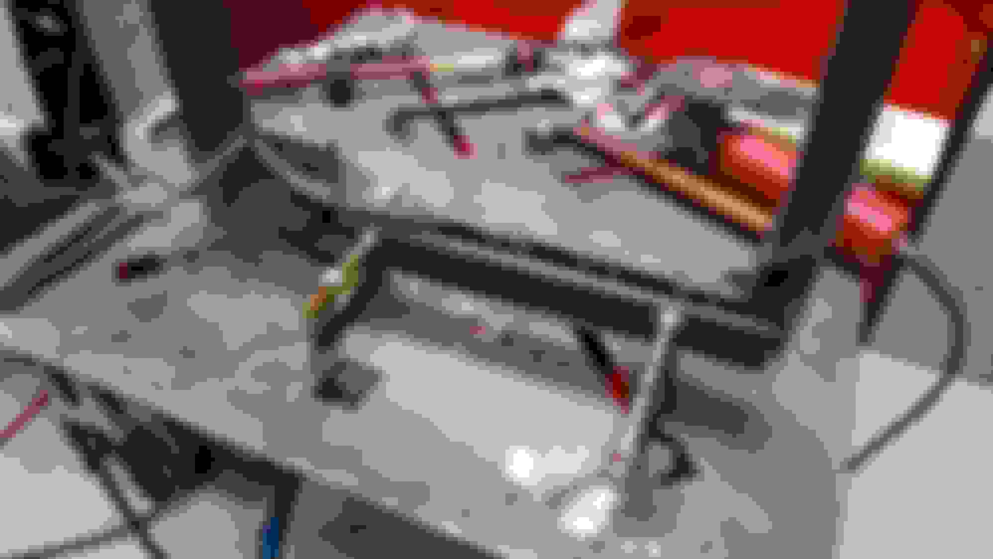
I managed to get the rear spindle bearings set up and ready for final install. I made a fixture out of a scrap grinding wheel blank. The machine shop that I work at makes diamond coated grinding wheels and cutters. This one was scrap because of the inside hole diameter. It worked great for me because the large hole gave clearance for the spindle support to go through. All I needed to do was drill four mounting holes.
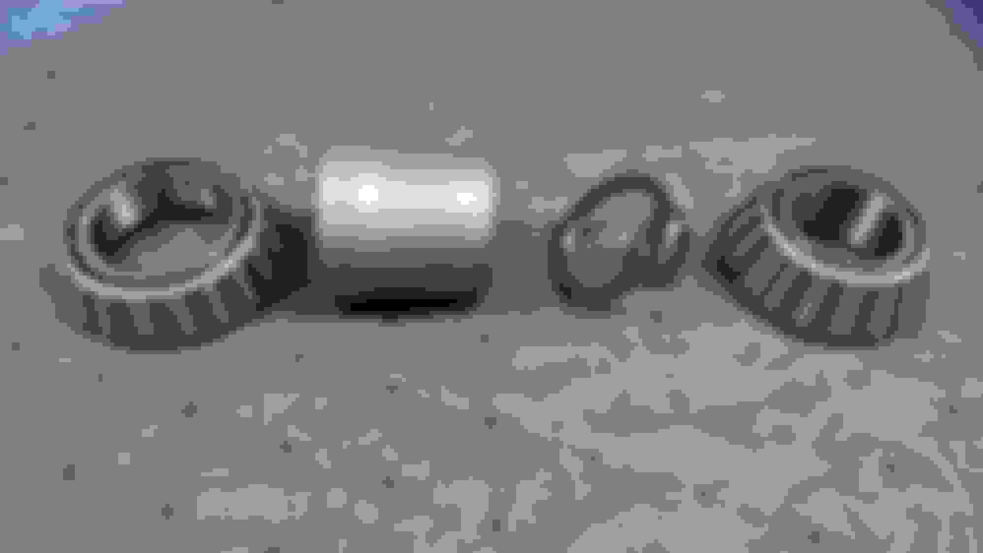
I pressed in the new races into the spindle supports. The bearings and races are all Timkin. I bought one of the bearing setup tools to do the job. It worked really nice. The original spacers ended up being small. After reading several articles about setting the bearings up, I decided to aim for .002" to .003" end play. The spec is .001-.008". .001" would be tight and .008" would just be really loose. One article said aim for .0015-.002", another said aim for .003". I decided that .002-.003" would be good. I re-ground the large spacers at both ends to square them up. I then made new spacers out of 4140 steel. The original small spacers were .130" thick for one and .131" thick for the other. I started out by making two new spacers at .140" thick thinking that I could grind them down to size. They ended up still being a little small. So, I made two more at .150" thick and ground those down to size. They ended up at .1425" thick for one and the other was .1455" thick. Bearings and spacers are now fitted and matched with each spindle support with .0025" of end play.
This is my end play fixture. Very simple. I just held the plate in a vice.
The large spacer is original. I ground both ends to make sure that they were flat and square. The small spacers were made from scratch using 4140 steel.
Just a reminder to be careful when you have parts powder coated. Powder coating adds lots of thickness and can effect how parts bolt back together. These parts should have had a lot of masking before they were powder coated. I ended up having to sand the powder coating off a lot of critical surfaces and then scuff everything and paint them.
Just a reminder to be careful when you have parts powder coated. Powder coating adds lots of thickness and can effect how parts bolt back together. These parts should have had a lot of masking before they were powder coated. I ended up having to sand the powder coating off a lot of critical surfaces and then scuff everything and paint them.
I jet coated my bell housing on the 63 and my mechanic was mad at me he had to sand down the matting points I didn't know about that but its very true.
I started installing the new universal joints in my half shafts. I'm not done yet. I put a new U joint on one end of each shaft and stopped. On both I can get the clip in one side but not quite in on the other. Those goofy clips that come with the U joints measure .059" thick. They do fit in the grooves when there is no U joint installed. Not sure if I have the wrong U joints, or if the new ones are just a little different, or what. I can't imagine that there is another U joint that is completely the same, just .010-.020" less wide. I ordered some snap rings that are supposed to only be .050" thick. I am going to see how well those work. Those might give me the extra clearance I need.
I also pressed a U joint into one of the half shaft flanges. What a pain in the @#$&^56% ! They came apart a lot easier. I made sure to bolt the two halves of the flange together to keep them from bending. They still flexed a lot when pressing the U joint in. I got the first one in, but it felt very stiff when moving it. I worked it in and out a little bit with the press and got it loosened up. Not sure, some how it was bound up. And I have the same issue with the retaining rings on this one also.
Half shaft with U Joint in one end and half shaft flange ready to have U joint installed. Notice how both halves of the flange are bolted together. This is to keep them from bending.
I'm anxious to see how you handle the u-joints. Most times when I have installed u-joints, the u-joints seem to be tight. I don't know the correct process to get them to move easier. I have supported the "other" sides of the u-joints (the sides not pressed into the flange) and flexed the flanges a bit to gain clearance. Like I said, I'm not sure this is a good process or not but it made sense to me.
You may need to rethink those upper shock mounts, unless you were planning on some fiberglass work. There is only about 1" of clearance between the stock mount and the side of the jack stowage compartment.
[QUOTE=buns;1593690367]You may need to rethink those upper shock mounts, unless you were planning on some fiberglass work. There is only about 1" of clearance between the stock mount and the side of the jack stowage compartment.
Way ahead of ya. I had already looked at that and knew that there would be some fiberglass work to do. I am not planning on this car carrying a jack or spare tire. Those compartments will be for other things.
FYI, I will also have to do fiberglass work around the drive shaft tunnel and probably under the seats.
O.K., I got the half shafts together. I ended up using the new snap rings on everything. Some of my problems were the actual retaining ring grooves in the half shafts and flanges. They are a little chewed up from years of use. Nothing serious. The thinner snap rings fit a lot better and give a little more clearance.
The issue the first flange I put together was that I did not have the two halves bolted together tight. Yep, I snugged the two halves up, pushed the U joint caps out a little, and then pushed then back in. After that everything was good.
I pushed the caps out like this. I pushed both caps out just a little. Doing it like this helped to take the stress out of the flange.
I pushed the caps back in like this. This kept the stress off of the flange. I pushed the first side in just enough to get the snap ring in. Then flipped it over and repeated. This set up does not always work. It depends on were the gap is in the U joint.
New snap ring vs. old retaining ring. The specs for the snap rings I used are on the bag.
 11-27-2016, 06:57 PM


 "
"


 I love seeing a fellow machinist using his skills on the forum!

 I am really happy with how they turned out, but man, that was a lot of machining. Below is a picture of how everything goes together. I will be working on assembling the rear spindle supports and mocking everything up. Before I do the final assembly of the rear suspension I will have the new parts coated with black oxide. I don't want to paint them and powder coating adds too much thickness.