When you click on links to various merchants on this site and make a purchase, this can result in this site earning a commission. Affiliate programs and affiliations include, but are not limited to, the eBay Partner Network.
The side yolks can be pinned with a hardened steel pin. Please keep us informed with the set up of the R&P. On mine, I got the pattern and backlash within spec; I slip fit the case into the carrier and swapped shims side to side. Here is my screw up; I went to add the
.010 preload on the case bearings, I added .005 to each side and proceeded to work all those shime into the carrier. I managed to destroy the shims and had to go back. I noticed with my purchased shim pack there are TWO thick shims and I wondered what they were for. YEP, after your pattern and backlash are set, mike the shims and add .005and then have that thick shim ground to that measurement on each sides total. Bingo, I was able to work the case with the ground shims into the carrier.
Brgds,
Rene
Thanks, I will ask my machine shop guys about the hardened pin.
I have not even looked at my shim set for the case bearings yet. If there is not thick shims in there I had already planned on making some. When I took mine apart that is what was in there. One thick shim on each side. I have seen other builds where they used shim stacks and I do not want to use those.
I also plan on making solid sleeves for the pinion gear and trailing arm bearings. I am not using crush sleeves.
Nice build thread. Good luck with it and keep the pics coming. Nice garage!
Gary
Thanks, I love my shop but you know what. No matter what you think when you are building it, you always end up thinking that you should have gone bigger.
I am still waiting for the other front spindle to be done at the powder coater but I am still working away at assembling the front passenger side.
I grease packed my bearings, put the inside bearing in the hub, and pressed in the seal. I then made sure that there was a thin film of grease on the seal and slide the hub onto the spindle. I installed the outer bearing, slid the washer on, and threaded the nut on.
Now, this is where I found a post here on the CF that I liked. It described a process that I liked for adjusting and torquing the hub bearings. Normally when I was younger I would have probably torqued it by feel while spinning the hub (YIKES!). Some say torque it to 12-15 ft lbs, back it off and put your cotter pin in (better). This post said to torque it to 15 ft lbs while spinning, loosen and back off, and then torque back to 50-60 in lbs while spinning. And always spin in the direction of forward movement. This is what I liked. It gives you measurable torques for setting the bearings and the clearance.
The other part of the post I liked was what to do if your cotter pin holes don't line up after being torqued. It said to use valve spring shims under the nut. I was able to purchase a set that were made by Comp Cams. The set included 16 each of .015", .030", and .045" thick shims. They are steel, the ID was .765", and the OD was 1.5". Perfect for using under the spindle nut and the set was only $21. If your holes do not line up you use a shim under the nut and that will change the final location of the nut when it is tight. I ended up using a .030" shim on the passenger side.
.030" valve spring shim.
Shim installed, perfect alignment of the holes for the cotter pin.
The other part of the post I liked was what to do if your cotter pin holes don't line up after being torqued. It said to use valve spring shims under the nut.
Why bother with shims? 1/6th of a turn on 20 threads per inch gives .008", and since there are TWO cotter pin holes 90* apart, now you're down to .004".
Why bother with shims? 1/6th of a turn on 20 threads per inch gives .008", and since there are TWO cotter pin holes 90* apart, now you're down to .004".
According to what I have read this method will give a .0005" to .001" bearing clearance. The tighter the bearings are set the less run out on the rotor. And like I said, I feel better about being able to tighten the bearings to some spec instead of loosening to what ever it may end up as. Thanks
Pretty straight forward. The new rotor slid right on. I had to use one shim at the top bolt of the caliper to square it up on the rotor. Installed the braided stainless steel flex line and done.
I am using SSBC performance brakes. Still 12" rotors but cross drilled and slotted. Aluminum 4 piston calipers with Hawk high performance pads. They now make 8 piston calipers. Maybe some day I will upgrade to those.
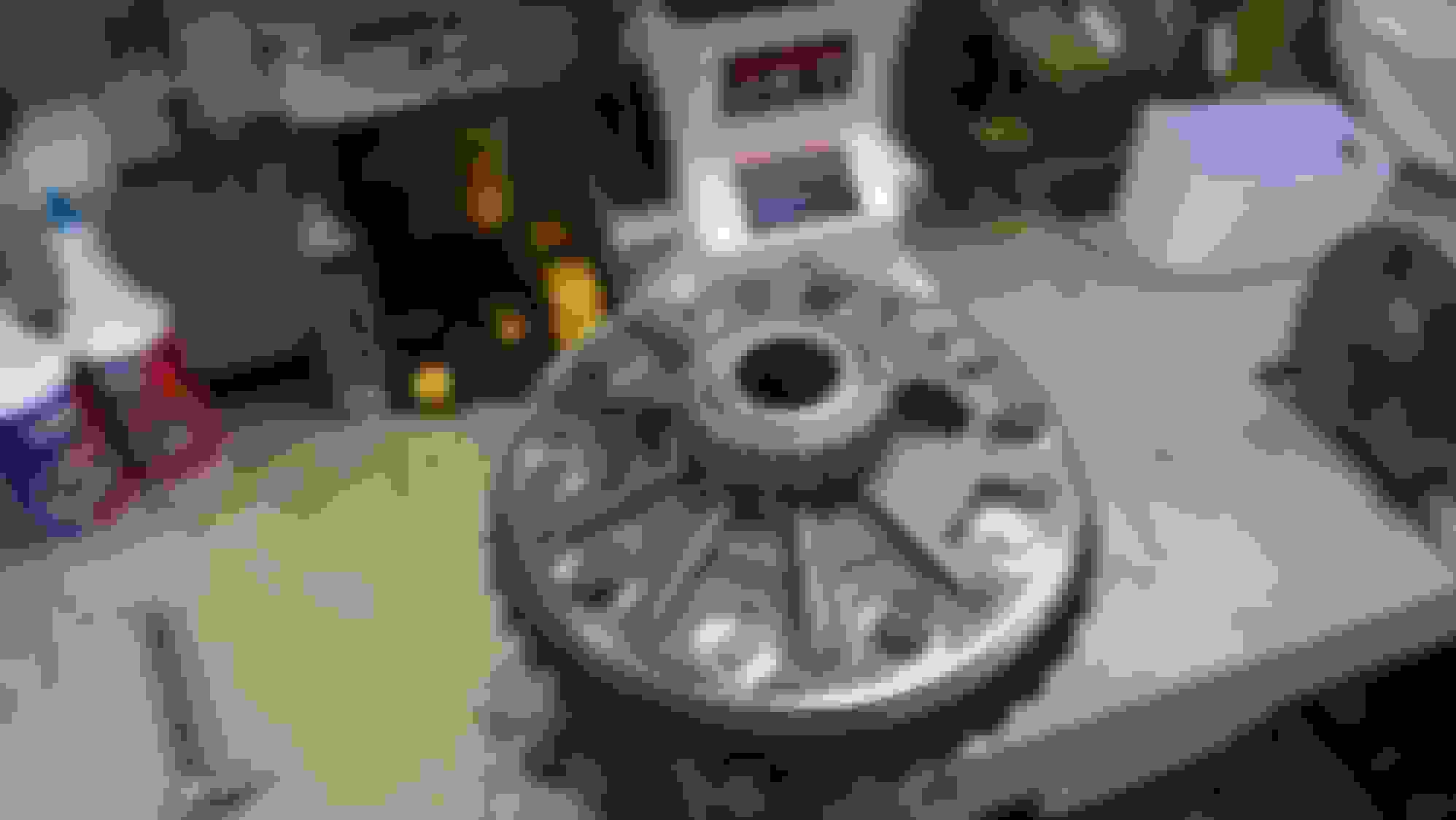
Time to press the bearings on the posi case. I think I mentioned before that my rebuild kit came with Timken bearings. I marked the matching race for the bearing that I used on the ring gear side so that I could keep them together. I don't think it would matter to much but I did it anyway. I wanted to keep the bearings and races matched.
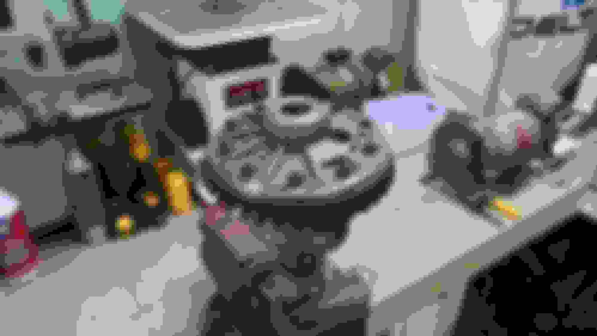
I cleaned the bearing surface real good on the case. I then cleaned the inside of the bearing real good. I used my 20 ton press and a socket just big enough to press on the inner race of the bearing. With this set up I was able to press the bearing just about all the way on before the socket interfered with the case. There was a small gap still between the bearing and case seat. I then grabbed one of the old bearings, cut it apart, and used the old inner bearing race to finish pressing the new bearing on until there was no gap.
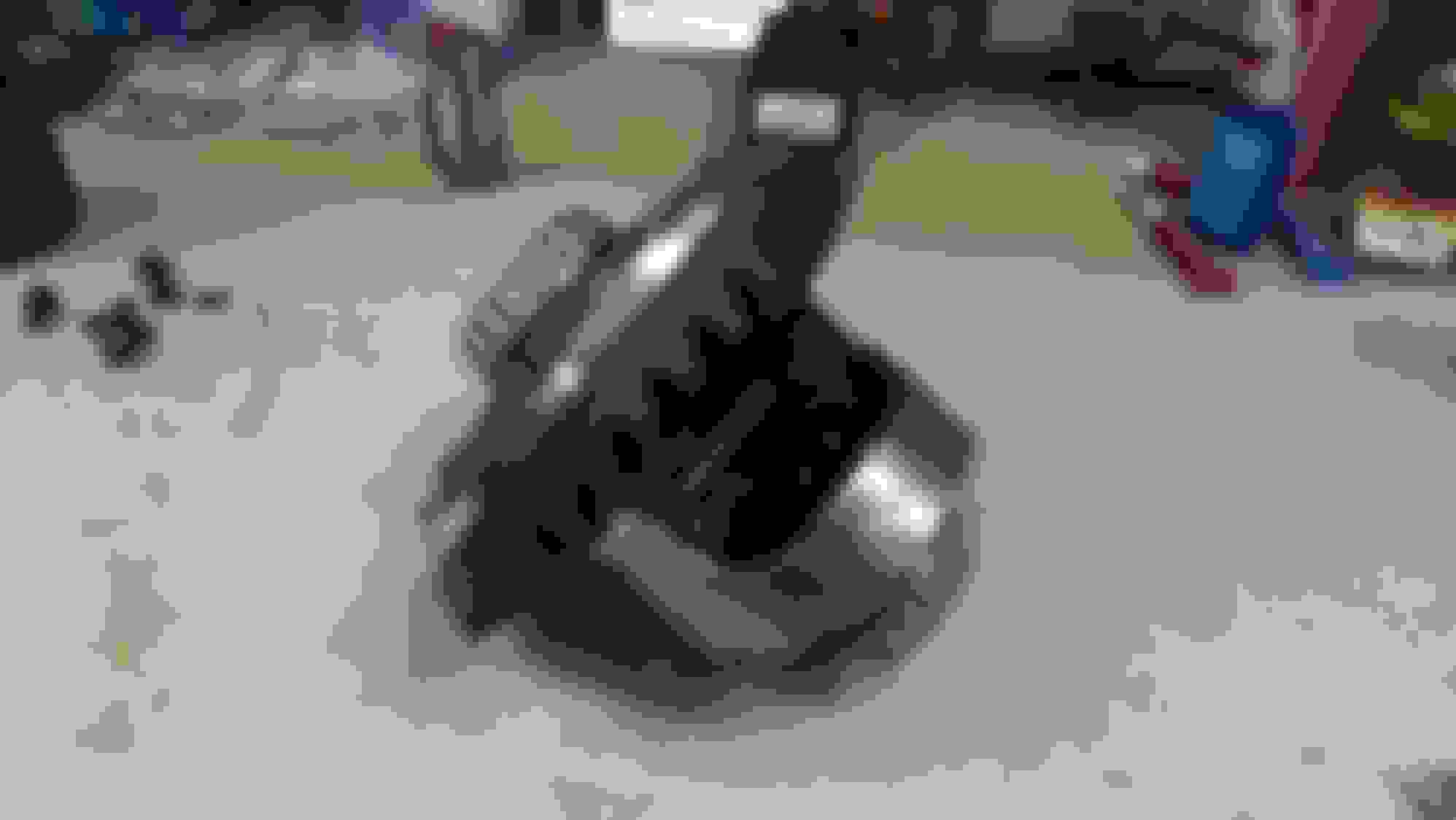
I then repeated the process for the other side with one difference. When you flip the posi case over and set it on the new bearing side it will not sit on the solid inner portion of the bearing. I actually needed to set it on another socket so that the outer portion of the bearing that I just installed would not be damaged.
I am now ready for the ring gear.
Pressing bearing on posi case.
Using old inner bearing race to seat new bearing completely down on the posi case.
New bearing installed with no gab at the bearing seat on the posi case.
O.K., The last step to the posi case is to install the ring gear.
I bought Richmond 3:70 gears to use in my Differential. I removed the ring gear from the box and blew it off and then used a stone to clean off the back and make sure it is flat. Washed it, dried it, blew it off, and then wiped the mounting face off with a rag and brake cleaner.
I have been keeping the posi case in a bag to keep it clean. I removed it from the bag and wiped off the ring gear flange. I took my stone and went over the ring gear flange again to make sure it was flat. I didn't want to blow it off because I did not want to get any of those filings inside it so I wiped it off real good. I then took a clean rag and sprayed some brake cleaner on it and wiped the flange off again. A lot of stuff (dirt and oil) still came off but now it was nice and clean.
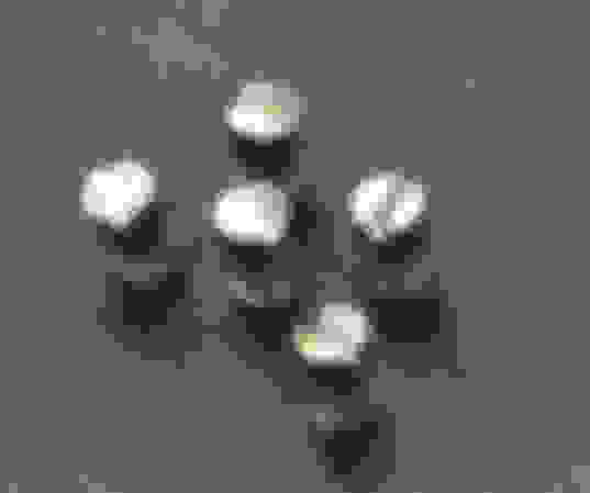
I had kept the old ring gear bolts to use as tools for installing the new ring gear. I took five of them and cut the heads off and then slotted the ends. These I threaded into every other hole and used as alignment studs for installing the ring gear. (a trick I learned from another post) I then aligned the ring gear and studs up with the holes in the posi case flange and used the remaining 5 bolts to suck the gear down on the flange.
I bought ARP ring gear bolts. I cleaned those with brake cleaner, wiped and blew them off. I then removed the 5 alignment studs from the ring gear, put loctite on five of the ARP bolts, threaded those into the five now vacant holes, and torqued them using a star pattern to 57 ft lbs. (spec was 55-60 ft lbs) Then I removed the five old bolts and repeated the install of the new ARP bolts in those holes.
Five alignment studs made from five old ring gear bolts.
Ring gear flange and ring rear stoned and cleaned. The ring has the alignment studs in it.
One of the other upgrades I am doing to the differential is a Tom's steel cap. There was quite a bit of machining to get this right and I have quite a few pictures so I am going to cover this in 2 or 3 posts.
First I bought the kit. I came with the steel cap, two 1/2-13 socket head cap screws, and also two 7/16-14 socket head cap screws for the other bearing cap.
The first thing I did was clean the bearing cap pads inside the housing. I wanted them good and clean but I did not want to distort them. I used my right angle die grinder and a small 3M medium grit pad. Not a disk. The pad will still remove material but nothing like a sanding disk.
Once I had the housing bearing pads clean I needed to drill out the existing 7/16-14 holes and tap them 1/2-13. I have a small mill at home but it was not large enough to get the housing into. I could have gone to my buddies machine shop but I decided to do it on my drill press. I would not recommend trying to hand drill them. I have a 20" drill press and the table tilts. So I rotated the table 90 degrees, used two angle blocks and bolted the housing to the table. I made sure the the housing was as perpendicular to the drill bit as I could by swinging a dial indicator across the housing cover face. I figured that surface was pretty close to parallel to the pads. I used a threaded rod in the 7/16 hole to help line up the drill chuck. After that I drilled the hole out to the proper tap size careful not to over drill it. Then used the drill press to align and start the tap. After that, tear it all down and start over for the other side. Piece of cake
In all it worked out well. The cap bolted right on and the bearing radius seemed to line up with the housing radius very well.
Tom's steel cap kit. It also came with two new 7/16-14 SHCS for the other cap.
These are the abrasive pads I use most of the time when cleaning gasket surfaces. In this case I used it to clean the bearing cap pads.
Housing set up for drilling and tapping the 1/2-13 holes.
The bearing cap pads drilled, tapped, and cleaned.
Fitting the bearings. I started by checking the stock cap that was being reused. This should be good, right (almost ). I grabbed the bearing race that was for the non ring gear side and put it in the journal and bolted the cap down. There was a couple of spots that I could get a .001" feeler gauge through and when it was loose there was no rock at all. It was close so I decided to stone the mating surface on the cap a little. That surface was not a real nice machined surface as it came stock. I was also afraid that if I tried to surface grind it I might remove to much. The stone worked out real nice. I rubbed the bottom of the cap on the stone a few times and checked it. I ended up rubbing it a few more times and kept trying it until when installed there was just barely a rock when loose (.001") and when tight I could not get a .001" feeler gauge in anywhere.
The upper cap is the one being used in my differential. This is after I rubbed it on the stone. The one below is the cap being discarded. It shows the stock rough machine surface.
Stock cap fitted and installed with now SHCS bolts.
Fitting the bearings, Tom's steel cap. I am sure these are manufactured and sent over sized so that they can be fitted to each individual housing. After all, I am sure that no two housings are the same. These were machined years ago, to lower standards, and a couple thousands here or there will make a difference with how the cap is fitted. I just makes sense.
O.K., I put the race marked "ring gear" into the journal, installed the steel cap, and tighten it down. I noticed right away that with a little effort, I could move the race up or down in the bore. I used some feeler gauges and determined that there was at least .017" clearance either at the top or bottom depending where the race was sitting. I new that there was actually more but could only get the .017" feeler gauge in because they just do not flex around the curve when they start getting thick.
Off to the machine shop. My buddies have a bore gauge and we quickly determined that there was actually .030" clearance. So we set the cap up in the mill and removed .020" and rechecked it. Yep, still needed to remove .010". .011" to get .001" rock. We went back to the mill and removed .009" and then went to the surface grinder and removed .002" and gave it a nice finish.
Now, when we first installed the cap before we removed any material, it centered itself really nice over the journal in the housing. But after we removed the needed material it didn't center itself as well at all. There was actually a lip on both sides where the radius of the cap met the radius on the housing. By removing one bolt at a time and checking we found that when one of the bolts was removed, the other by itself would let us center the cap. When we re-installed the other bolt, it drew the cap back of center. So with that one bolt hole (the one we could remove and get the adjustment we wanted) we opened it up an extra 1/64". That fixed the problem and allows the cap to center itself.
Now that all the machining was done, we put the race in the journal, installed the cap and tightened it down. Perfect. We could not get a .001" feeler gauge under the race anywhere. And when we loosened the bolts there was exactly .001" rock. Maybe slightly more, but not .002"
Tom's steel cap in the mill ready to remove material,
Steel cap in the surface grinder for a slight material removal and clean up.
We opened up just this one hole in the cap to allow it to center itself over the journal.
Both caps installed and fitted. I am now ready to start work on the pinion gear.
Thanks for making this thread, esp. with so many fine photos. It is always a pleasure to watch an especially skilled and thorough craftsman work on a worthwhile project.
Thanks for making this thread, esp. with so many fine photos. It is always a pleasure to watch an especially skilled and thorough craftsman work on a worthwhile project.
Ha, you guys are all to nice. If you only knew what really goes on in my shop you would laugh. I owe a lot of what I do to others here on the forum and out in the real world. I just read a lot and am not afraid to try something and risk messing it up is all.
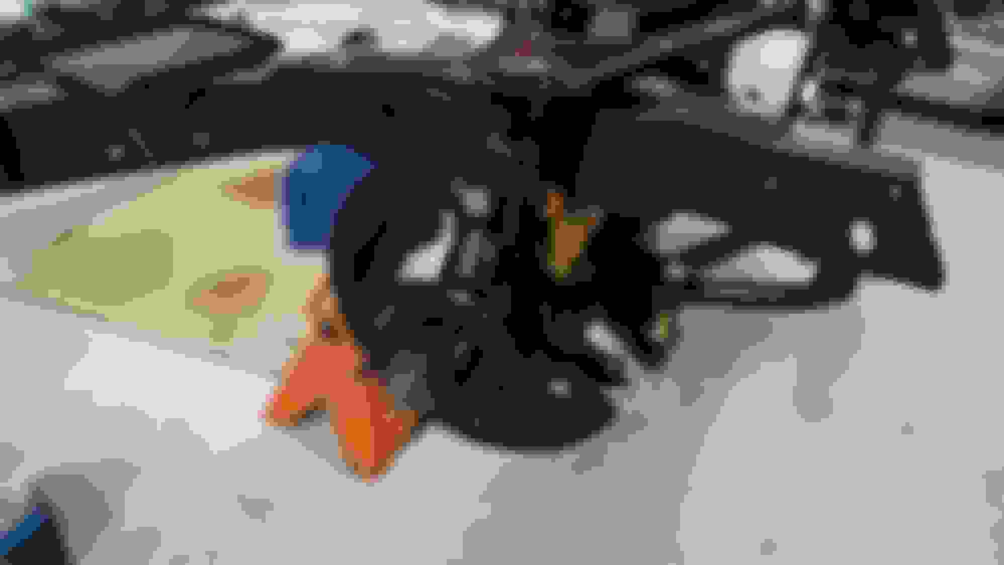
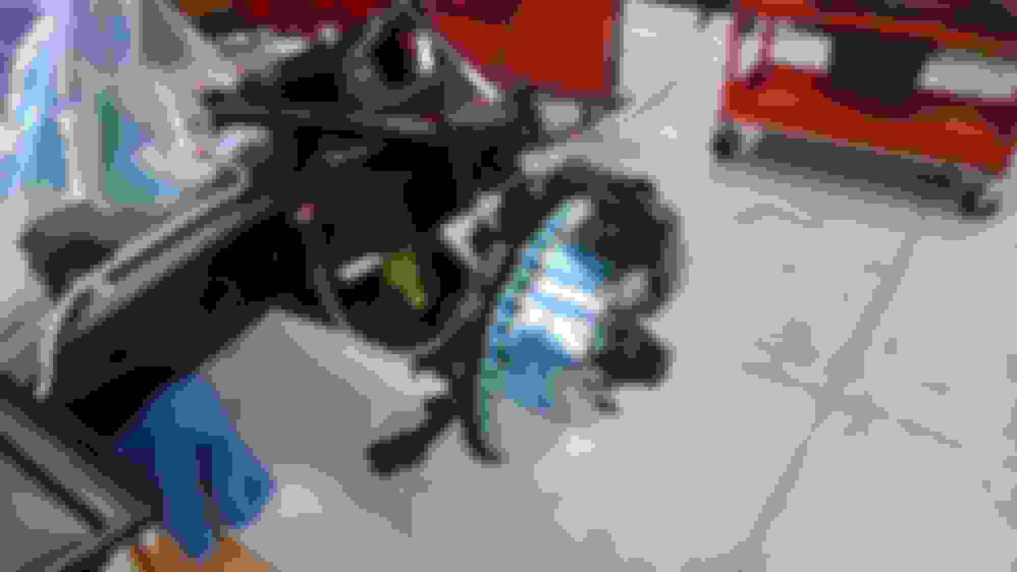
I pressed in the bearings today. Everything went pretty smooth. I used my press. Made sure that everything was clean and that there were not any nicks or burrs to catch on. It was a little difficult getting the side yoke bearings in because there is not a flat surface on the side of the housing to rest it on. I had to do a little blocking it up to get it straight and get them in.
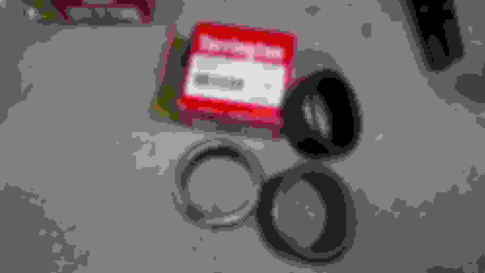
I also bought different side yoke bearings than what came with my kit. My differential had Torrington bearings in it originally. I noticed several threads discussing these bearings and the differences with some others that have half the rollers in them. My kit came with the ones that have half the rollers so I decided to special order new Torringtons. I don't know which are better, I just like the Torringtons.
The only thing I would have done differently would be to press the inner pinion bearing first. If I had pressed the inner bearing first I could have used the surface that the outer bearing sets on as a surface to press against. I could have placed a large socket in there to set the housing on. I was still able to press in the inner bearing in after the outer was in by placing the housing on end. It was just afterwards I thought the other way might have worked better.
Directly under the box is the new bearing. To the right of the box is one of the old bearings. And leaning on the new bearing is the other type of bearing with half the rollers.
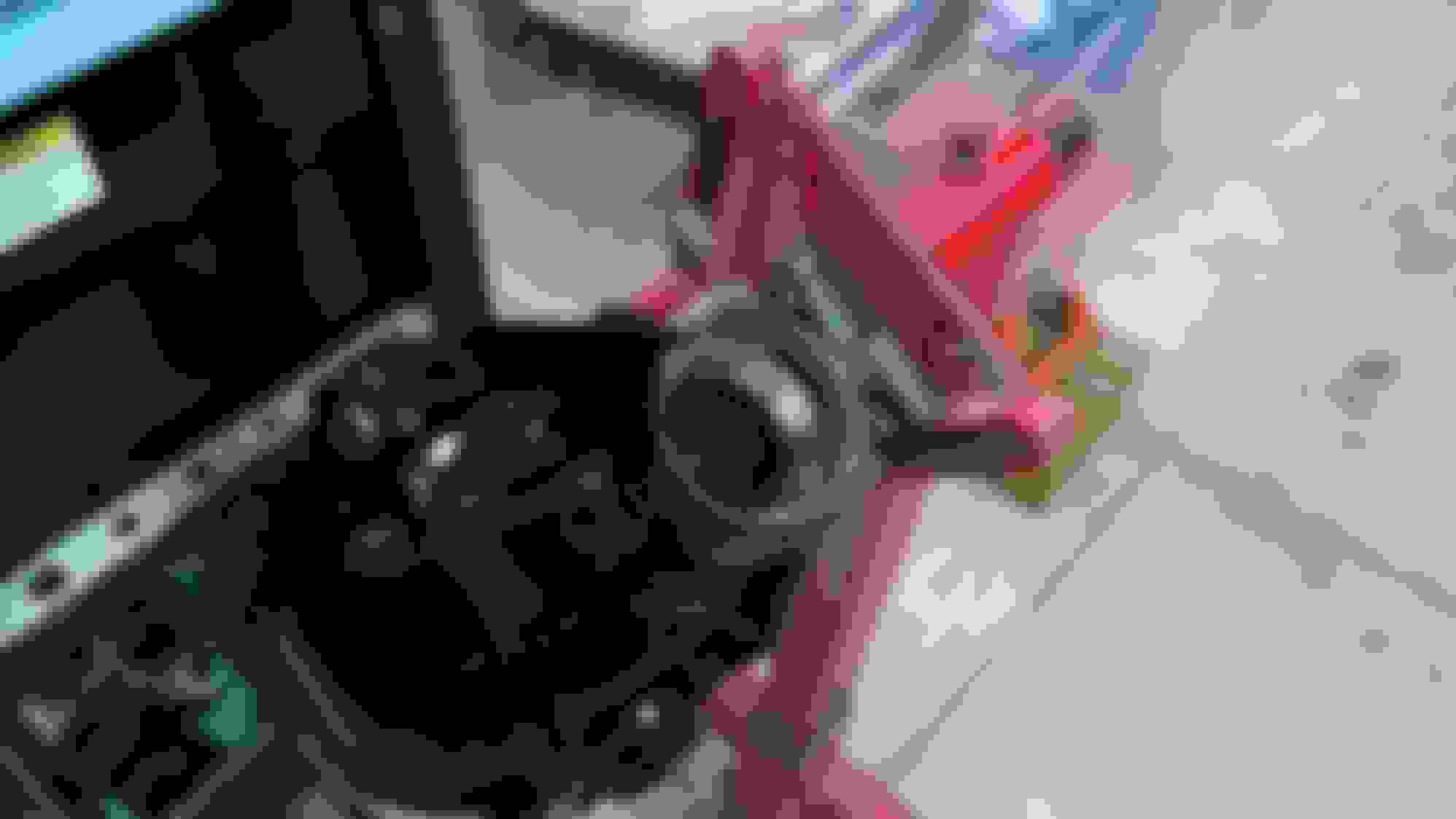
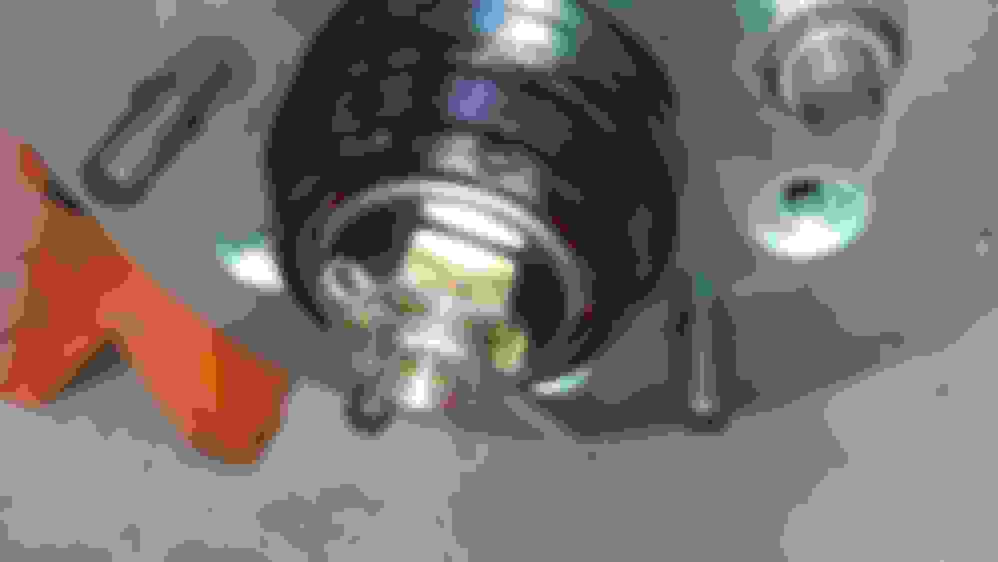
Pressing the first pinion bearing. This was the easy one.
Ha, you guys are all to nice. If you only knew what really goes on in my shop you would laugh. I owe a lot of what I do to others here on the forum and out in the real world. I just read a lot and am not afraid to try something and risk messing it up is all.
Thanks, Sam
I agree with everyone else. When people take the time to post such detailed photos, it makes life so much easier on the rest of us when we go about doing these projects.
I now know who to bug/bribe when I go to rebuild my diff.
 02-22-2015, 02:11 PM


 ). I grabbed the bearing race that was for the non ring gear side and put it in the journal and bolted the cap down. There was a couple of spots that I could get a .001" feeler gauge through and when it was loose there was no rock at all. It was close so I decided to stone the mating surface on the cap a little. That surface was not a real nice machined surface as it came stock. I was also afraid that if I tried to surface grind it I might remove to much. The stone worked out real nice. I rubbed the bottom of the cap on the stone a few times and checked it. I ended up rubbing it a few more times and kept trying it until when installed there was just barely a rock when loose (.001") and when tight I could not get a .001" feeler gauge in anywhere.