C1 & C2 Corvettes General C1 Corvette & C2 Corvette Discussion, Technical Info, Performance Upgrades, Project Builds, Restorations

Gas gauge

Thread Tools
 
Search this Thread
 
Old 11-23-2015, 04:08 PM
  #1  
Holmqvistar
Advanced
Thread Starter
 
Holmqvistar's Avatar
 
Member Since: Aug 2013
Location: Helsingborg
Posts: 89
Received 2 Likes on 2 Posts
Default Gas gauge

Hi.

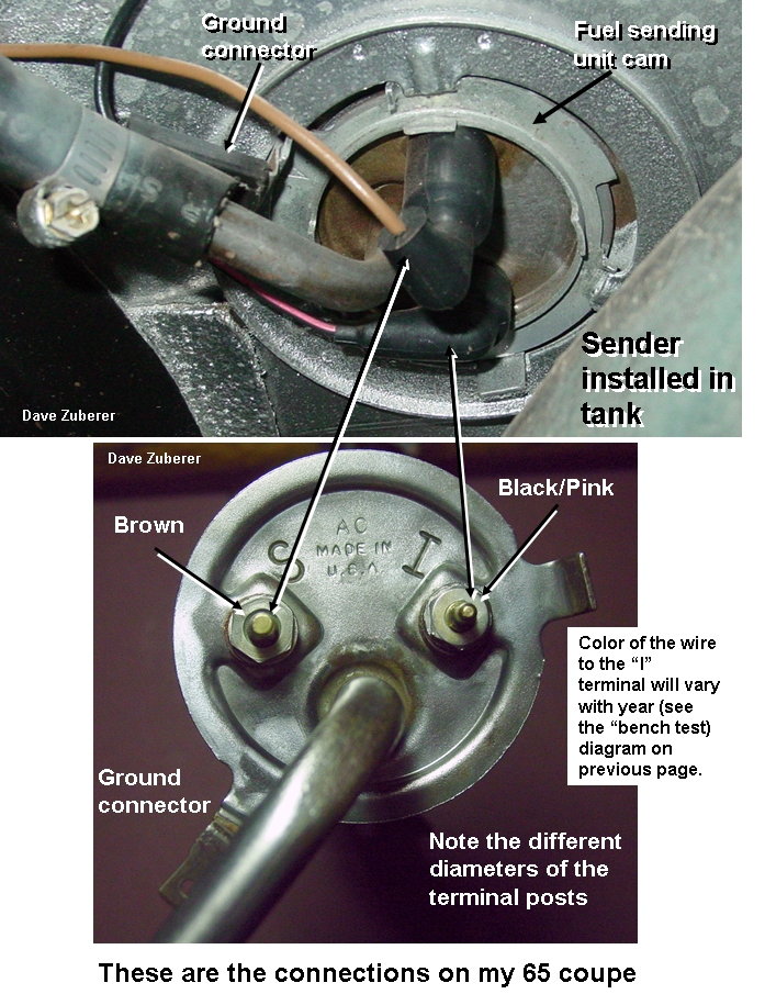
How much resistanse shall i have in the black/pink wire to the gasgauge.
There is a resistor on the wire.
Its a 64 327.

Best regards Fredrik
Old 11-23-2015, 04:20 PM
  #2  
JohnZ
Team Owner

Support Corvetteforum!
 
JohnZ's Avatar
 
Member Since: Oct 2000
Location: Washington Michigan
Posts: 38,899
Received 1,857 Likes on 1,100 Posts

Default

Originally Posted by Holmqvistar
Hi.

How much resistanse shall i have in the black/pink wire to the gasgauge.
There is a resistor on the wire.
Its a 64 327.

Best regards Fredrik
None. There is no resistance in the 12V feed circuit to the gauge "I" terminal; the gauge requires 12 volts to work properly. That same circuit also powers the temperature gauge.

Last edited by JohnZ; 11-23-2015 at 04:21 PM.
Old 11-23-2015, 04:34 PM
  #3  
Holmqvistar
Advanced
Thread Starter
 
Holmqvistar's Avatar
 
Member Since: Aug 2013
Location: Helsingborg
Posts: 89
Received 2 Likes on 2 Posts
Default

Originally Posted by JohnZ
None. There is no resistance in the 12V feed circuit to the gauge "I" terminal; the gauge requires 12 volts to work properly. That same circuit also powers the temperature gauge.
Ok, but to the "sender" in the tank?
I found a resistor on a black pink wire that runs from the dash to the rear of the car.
Old 11-23-2015, 05:45 PM
  #4  
DZVette
Melting Slicks
Support Corvetteforum!
 
DZVette's Avatar
 
Member Since: Sep 2001
Location: Aggieland TX
Posts: 2,627
Received 735 Likes on 455 Posts

Default

Originally Posted by Holmqvistar
Ok, but to the "sender" in the tank?
I found a resistor on a black pink wire that runs from the dash to the rear of the car.
John is referring to the "I" terminal on the sender unit. See photo below.
DZ


PDF file is attached with more details.
Attached Images

Last edited by DZVette; 11-23-2015 at 05:47 PM. Reason: PDF file added
Old 11-24-2015, 11:47 AM
  #5  
Holmqvistar
Advanced
Thread Starter
 
Holmqvistar's Avatar
 
Member Since: Aug 2013
Location: Helsingborg
Posts: 89
Received 2 Likes on 2 Posts
Default

Originally Posted by DZVette
John is referring to the "I" terminal on the sender unit. See photo below.
DZ


PDF file is attached with more details.
Is there any way to test the gauge and the cables easy?
Putting a low current from the tank cabels to the gauge just to see if the cabels and the gauge is ok?
Old 11-24-2015, 08:11 PM
  #6  
JohnZ
Team Owner

Support Corvetteforum!
 
JohnZ's Avatar
 
Member Since: Oct 2000
Location: Washington Michigan
Posts: 38,899
Received 1,857 Likes on 1,100 Posts

Default

Originally Posted by Holmqvistar
Is there any way to test the gauge and the cables easy?
Putting a low current from the tank cabels to the gauge just to see if the cabels and the gauge is ok?
Read the paper below on midyear fuel gauge diagnostics, and the diagram below goes with it.

http://www.lbfun.com/warehouse/tech_...rFuelGauge.pdf
Attached Images  
Old 11-24-2015, 11:34 PM
  #7  
rayvaflav
Le Mans Master
Support Corvetteforum!
 
rayvaflav's Avatar
 
Member Since: Apr 2006
Location: Oklahoma City Oklahoma
Posts: 5,976
Received 979 Likes on 491 Posts

Default

Do a resistance test on the wires from the gauge to the sender. The sender operates at full sweep from 0 to 90 ohms. Disconnect the level wire and it will go past full, ground it and it pegs on empty.

Ray

Get notified of new replies

To Gas gauge


Quick Reply: Gas gauge


All times are GMT -4. The time now is 09:19 PM.