Starter wiring
 01-17-2016, 06:59 PM
#1
Cruising

Thread Starter

Member Since: Sep 2011
Location: Granada Hills California
Posts: 10
Likes: 0
Received 0 Likes
on
0 Posts

I'm in the process of putting a high torque starter in my '63. The new starter seems to have a terminal for battery voltage, and a terminal for the violet wire (ignition switch) to energize the solenoid. I have the external resistor style coil, and a pink wire from the ignition switch to the coil, and another pink wire for 12v during the starting crank. I'm using the stock wire diagram, which shows another terminal on a stock starter.
My question: Can I run the un-restricted 12v pink wire from the starter cranking side terminal to the coil?
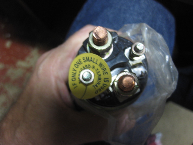
See attached picture that have the battery cable, electric fan, red wire to vr, black wire to amp gauge hooked to the 12V battery terminal, the violet to the solenoid terminal, and the pink that goes to the coil, attached to the starter post. Will the pink function here? Do I need to seek another cranking source for the coil?
Thanks for any help,
Tom G
My question: Can I run the un-restricted 12v pink wire from the starter cranking side terminal to the coil?
See attached picture that have the battery cable, electric fan, red wire to vr, black wire to amp gauge hooked to the 12V battery terminal, the violet to the solenoid terminal, and the pink that goes to the coil, attached to the starter post. Will the pink function here? Do I need to seek another cranking source for the coil?
Thanks for any help,
Tom G
 01-17-2016, 07:16 PM
#2

I'm in the process of putting a high torque starter in my '63. The new starter seems to have a terminal for battery voltage, and a terminal for the violet wire (ignition switch) to energize the solenoid. I have the external resistor style coil, and a pink wire from the ignition switch to the coil, and another pink wire for 12v during the starting crank. I'm using the stock wire diagram, which shows another terminal on a stock starter.
My question: Can I run the un-restricted 12v pink wire from the starter cranking side terminal to the coil?
See attached picture that have the battery cable, electric fan, red wire to vr, black wire to amp gauge hooked to the 12V battery terminal, the violet to the solenoid terminal, and the pink that goes to the coil, attached to the starter post. Will the pink function here? Do I need to seek another cranking source for the coil?
Thanks for any help,
Tom G
01-17-2016, 08:20 PM
#4
Le Mans Master

Member Since: Oct 2002
Location: Las Vegas - Just stop perpetuating myths please.
Posts: 7,098
Received 373 Likes
on
356 Posts

Man i swear i answer a '63 starter wiring question here weekly. Why always '63?
Ok the "pink" wire goes to pos + of coil and has its own terminal post (usually small). That will be a terminal switched by the solenoid internal contactor. U can verify this terminal with all the wires off the solenoid it will will show open or infinite resistance to ground. Now i should say measuring to ground would mean the case of the starter w/starter out of car or any part of the frame/drivetrain with starter installed.
The "violet" wire is powered from the ign sw and if u measure that resistance to ground (again w/all wires off solenoid) u should have close to zero reistance or only a few ohms. Now i should ention again that measuring to ground would mean the case of the starter w/starter out of car or any part of the frame/drivetrain with starter installed. BTW this terminal connects the ign sw to the solenoid coil and has its own terminal also - must have its own terminal.
Finally the red wire connect to a large terminal lug/post which also is switched by the internal contactor and should have infinite resistance to ground (open) also.
I cant recognize or tell how your solenoid terminals are label from Nevada but u should be able to verify correct terminals using resistance checks.
What i think maybe confusing u is there is no terminal for the "pink" coil wire as many aftermarket starter wont have a terminal for this. In that case the starter is ususally a hi-torque starter and u just need to remove the pink wire or cut of the terminal at the solenoid end and tape it back.
Whew! Good luck.
01-17-2016, 09:55 PM
#5
Cruising
Thread Starter
Member Since: Sep 2011
Location: Granada Hills California
Posts: 10
Likes: 0
Received 0 Likes
on
0 Posts
Just came in from working on this problem. Cardo0 you've confirmed my suspicions about the pink wire to a aftermarket starter. Thanks man, I'll guess I still need to pick up 12V to by-pass the resistor during the start, and I guess I'll go directly to the ignition switch. On to the next problem.
01-17-2016, 10:05 PM
#6
Team Owner


I'd have to dig back through my notes but when I put a mini starter on my 67 Chevelle I had to add a diode in the starter circuit to keep voltage from feeding back into the ignition. Not sure I remember specifics; others here might.....
01-17-2016, 10:35 PM
#7
Cruising
Thread Starter
Member Since: Sep 2011
Location: Granada Hills California
Posts: 10
Likes: 0
Received 0 Likes
on
0 Posts
Frankie,
I think you're right. At one point I found the starter getting feed back voltage thru the pink wire. If you come across your notes, let me know how you did it.
Thanks,
Tom G
I think you're right. At one point I found the starter getting feed back voltage thru the pink wire. If you come across your notes, let me know how you did it.
Thanks,
Tom G
01-18-2016, 07:22 AM
#8
Team Owner
I have no idea if these notes will apply to your situation or apply to a mini starter on a Corvette vs a Chevelle:
"As part of above starting problem the start cycle needs to provide 12V to the + side of the ignition coil. Ran wire from the starter’s 12V lead (provided by the ignition switch when turned to “START” position” to the + side of coil with a diode installed to prevent the DC voltage from the coil when in “RUN” state engaging the starter. The cathode (banded end) of the 3Amp / 400PIV diode needs to point towards the coil. Start up problem fixed!"
"As part of above starting problem the start cycle needs to provide 12V to the + side of the ignition coil. Ran wire from the starter’s 12V lead (provided by the ignition switch when turned to “START” position” to the + side of coil with a diode installed to prevent the DC voltage from the coil when in “RUN” state engaging the starter. The cathode (banded end) of the 3Amp / 400PIV diode needs to point towards the coil. Start up problem fixed!"
Last edited by Frankie the Fink; 01-18-2016 at 07:22 AM.
01-18-2016, 07:54 AM
#9


To prevent feedback, use a diode (3 or 5 amp) in line to the motor terminal (pink). Banded end will be oriented away from the starter. I used to sell mini conversion starters, but I used a 4 post solenoid on them. I still have a few.
01-18-2016, 08:03 AM
#10
Team Owner
Never needed it though

 This fits starter being used in op post
01-18-2016, 10:38 AM
This fits starter being used in op post
01-18-2016, 10:38 AM
#12
Cruising
Thread Starter
Member Since: Sep 2011
Location: Granada Hills California
Posts: 10
Likes: 0
Received 0 Likes
on
0 Posts
I'm going to pick up a couple 5A diodes today. All the info you guys have supplied has defnately been of help and my fooling with this problem has resulted in finding that without a diode, voltage feedback to the starter will try to keep it spinning.
I'll post what I end up with.
Thanks,
Tom G
I'll post what I end up with.
Thanks,
Tom G
01-18-2016, 12:05 PM
#13
Team Owner
I'm going to pick up a couple 5A diodes today. All the info you guys have supplied has defnately been of help and my fooling with this problem has resulted in finding that without a diode, voltage feedback to the starter will try to keep it spinning.
I'll post what I end up with.
Thanks,
Tom G
I'll post what I end up with.
Thanks,
Tom G
 01-18-2016, 12:46 PM
#14
I'm going to pick up a couple 5A diodes today. All the info you guys have supplied has defnately been of help and my fooling with this problem has resulted in finding that without a diode, voltage feedback to the starter will try to keep it spinning.
I'll post what I end up with.
Thanks,
Tom G
I'll post what I end up with.
Thanks,
Tom G
01-18-2016, 03:07 PM
#15
Le Mans Master
Member Since: Oct 2002
Location: Las Vegas - Just stop perpetuating myths please.
Posts: 7,098
Received 373 Likes
on
356 Posts
I think what your doing will work. Myself i would test the small term resistance to ground and each other terminal. If open or infinite resistance to all others then it will only get power while the solenoid is pulled in. It will only put full batt/12v on the coil when the solenoid pulls in and kicks out the pinion gear. But a diode wont harm anything and if it feels better to use one here then it will work.
The other 2 terminals look like one for a large for the red batt cable w/ other smaller red wires laid on top. This will be open and infinite resistance (to gnd and the other terminals) also until the solenoid pulls in. The last large term is for the internal solenoid coil wire and that should have very low or zero resistane to gnd but open/infinite to the other terminals. This is for the violet wire from the ign sw.
Now i dont have my '63 wiring dwg w/me here so i cant tell u what a forth term should do or where the black wire (i recall) goes. But i think u have a handle on it now.
Good luck and let us know what works and what doesnt - it helps us all.
Last edited by cardo0; 01-18-2016 at 03:08 PM.
01-18-2016, 04:19 PM
#16
Solenoid 3 post (what Tom has) Terminal Id. Large post-Battery (where Battery cable and acessory wires go. Other large post- Motor connected to starter field lead. (Comes out of starter) Small post S- switch (where purple wire goes) comes from Ign switch. 4 post solenoid has additional small post R goes to coil to supply 12v when cranking. Tom does not have this post. Battery and R post have no connection to ground S and Motor post are grounded.
The following users liked this post:
cardo0 (01-18-2016)
01-18-2016, 09:24 PM
#17
Le Mans Master
Member Since: Oct 2002
Location: Las Vegas - Just stop perpetuating myths please.
Posts: 7,098
Received 373 Likes
on
356 Posts
Ok i think i can see the solenoid to motor wire. Connection to that terminal is kinda in the shadow. So good catch Stella. That terminal is only for the solenoid to motor wire. Many starter motors that will be a solid piece of copper. So its a true high torque starter. The small term only carries the violet wire from the ign sw then. I dont want to advise about the diode then as i have never used one.