When you click on links to various merchants on this site and make a purchase, this can result in this site earning a commission. Affiliate programs and affiliations include, but are not limited to, the eBay Partner Network.
There is a plate that runs the length of the rocker
I have a photo of a 59 with the rocker off.....
see if I can post it up
I have both the left and right rear halves of these plates with zero corrosion (each over a foot long), came with a rear clip I bought.
I had my originals of these (full length) hot dip galvanised as a fair bit of crud can accumulate in the cavity area and if the top sides of these mounts are shagged then I bet the hidden steel support is rotten as well. One side of mine was about 90% full with dirt a bullet, 1960s lipstick and some coins and bits of other crap.
It is also riveted along the length of the door sill with about 8 rivets on the top side and about 12 rivets on the bottom side and then is joined/riveted/bolted to the front mount point and birdcage behind the firewall. These steel section basically provided the rigidity between the front and rear of the car.
Looks nasty, but if you are doing a resto and the paint doesn't matter is a pretty straight forward task though initially it will look pretty destructive. You will need to purchase an aftermarket left and right side panel as these will be pretty much destroyed in trying to keep the floor section undamaged; I bought the full side panel that is basically the size of the pieces that have been removed. You need to separate the bonding glue/resin between the individual panel pieces and buy yourself a die grinder with some nice course burrs to remove the old glue once the panels are apart.
I bought the rivets and riveting dollies etc from an aeronautical tool shop for about $200 in the US. Way cheaper than buying rivets from a corvettes spares outlet.
If you need more info for rivet sizing and tooling, I can scratch around and be more specific and I probably have more photos of the process.
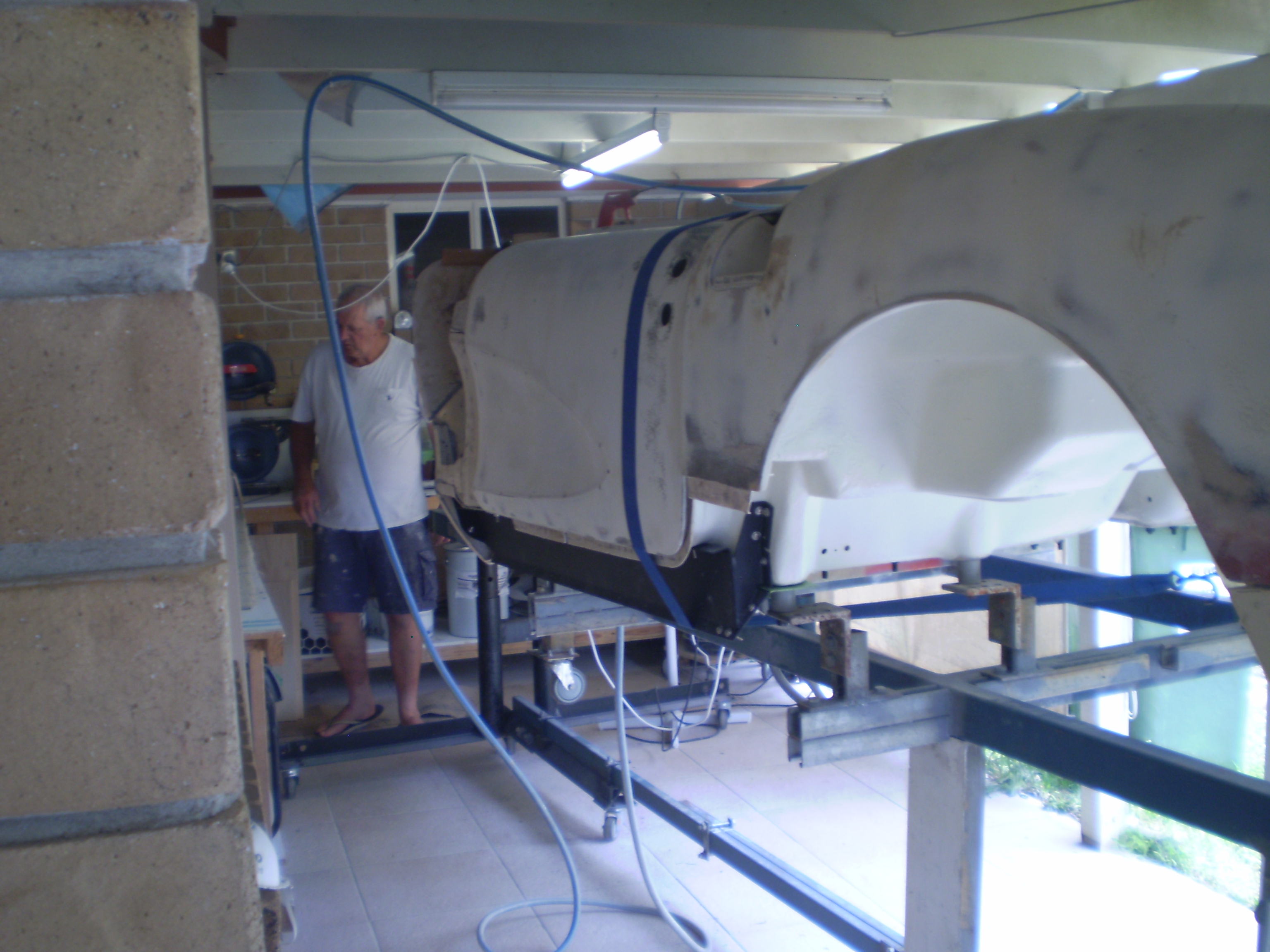
Wait... Isn't the body supposed to be upside down?
I should have speared it in the ground up to the doors like that dude did with those Cadillacs in Texas or where-ever; that would have solved lots of my resto problems and saved my bank account.
I don't think it has ever been completely upside down on the rotisserie.
I should have speared it in the ground up to the doors like that dude did with those Cadillacs in Texas or where-ever; that would have solved lots of my resto problems and saved my bank account.
I don't think it has ever been completely upside down on the rotisserie.
That did not work with this one...
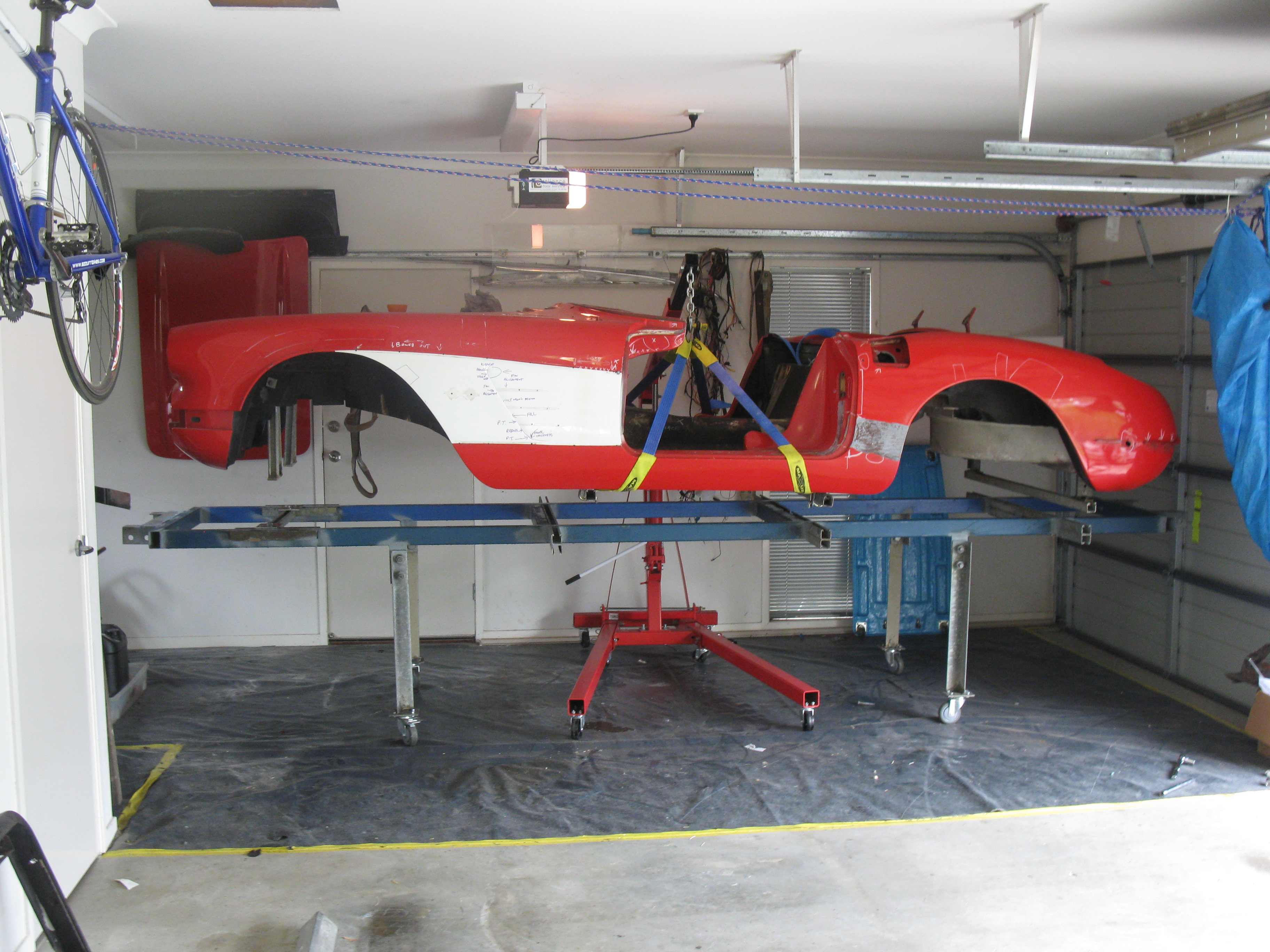
But I have seen one car in a rotisserie (my car):
Rocker panels were replaced with the same braces replaced:
Yeah project creep, I will study all these pics and go for it , more pics would be cool. I think now is the time to do it. All my body glass is good but the metal parts have rusted from sitting for 40 years in humid garage. Chip
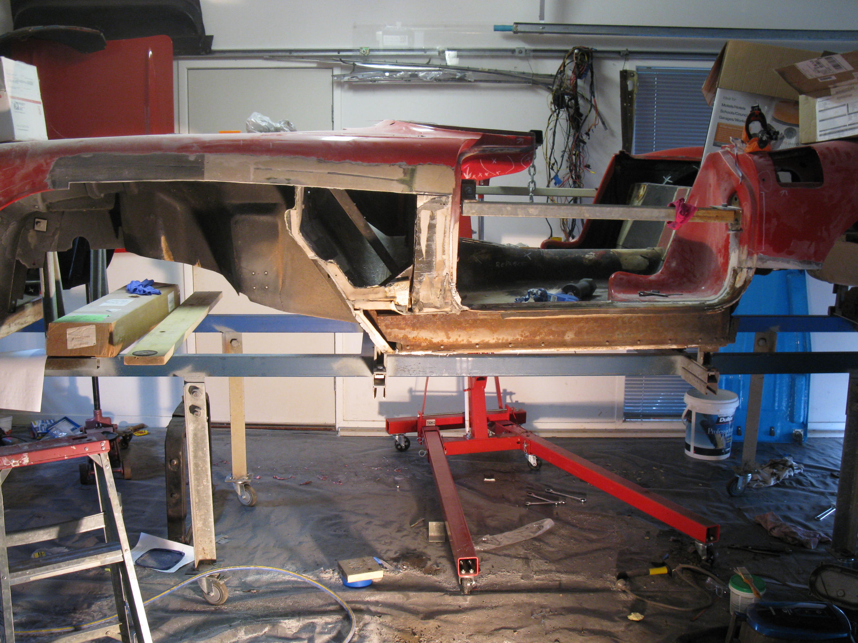
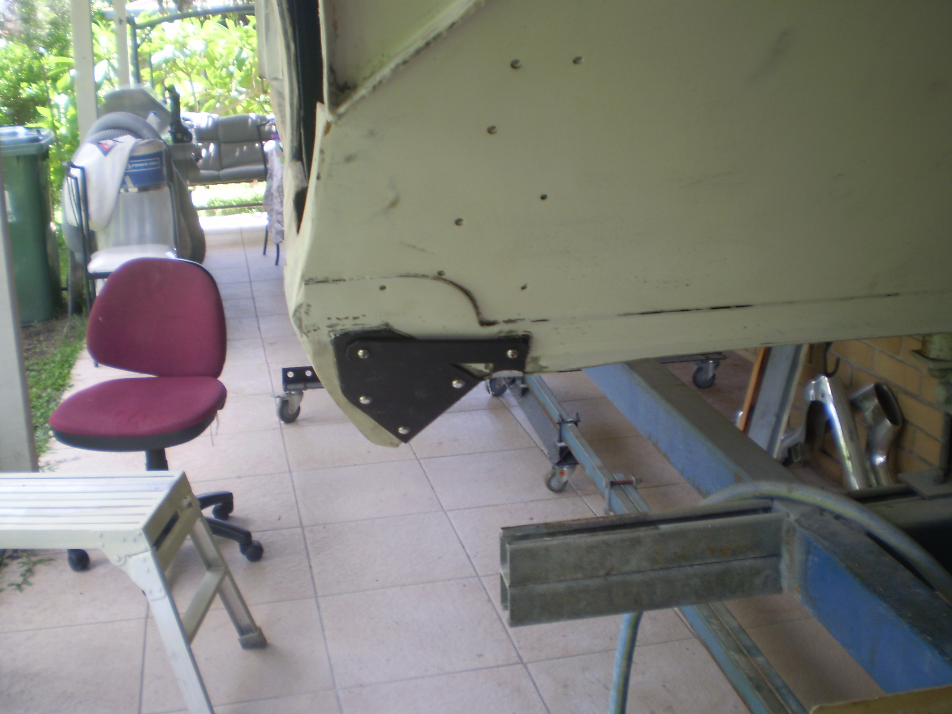
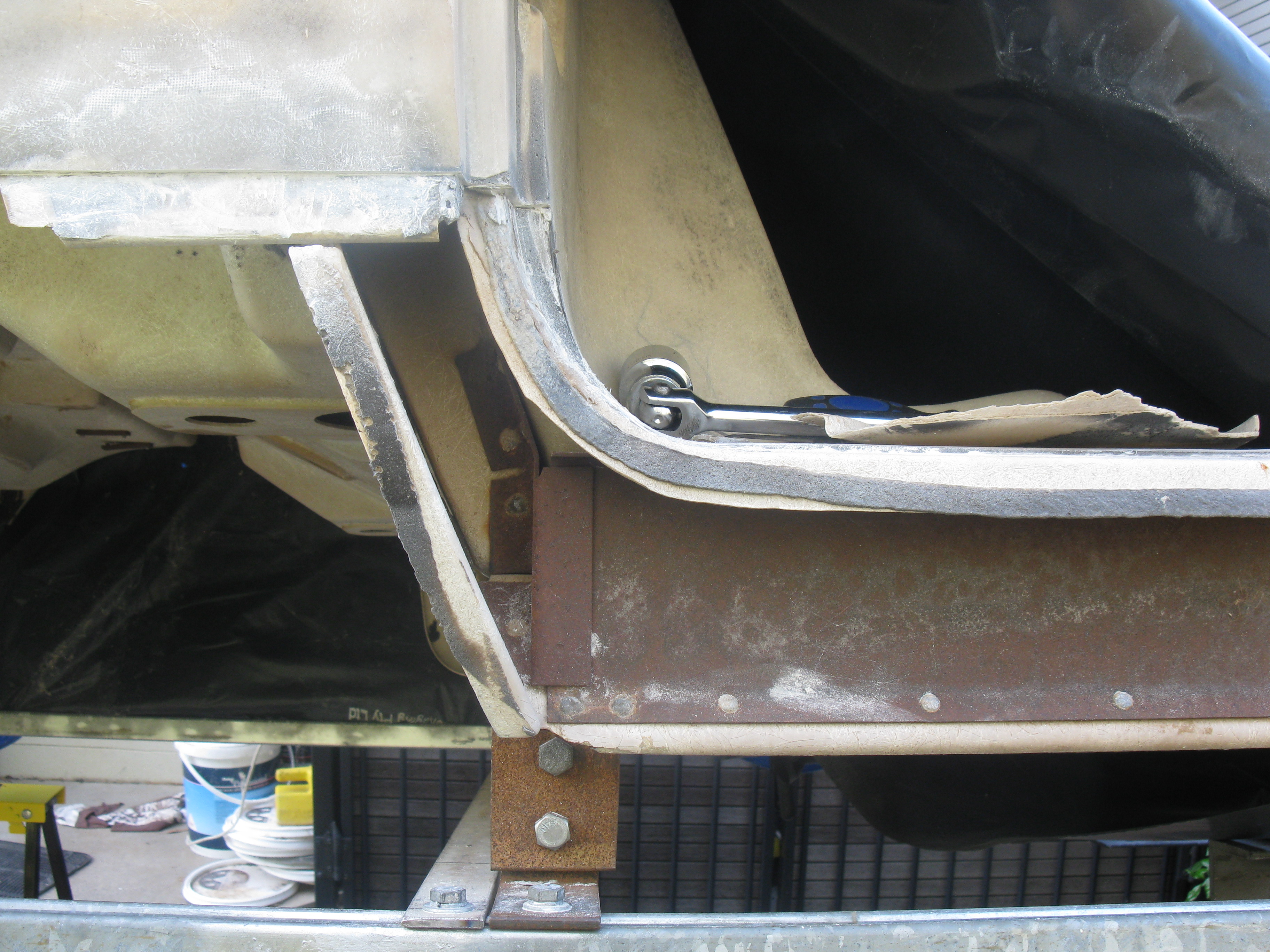
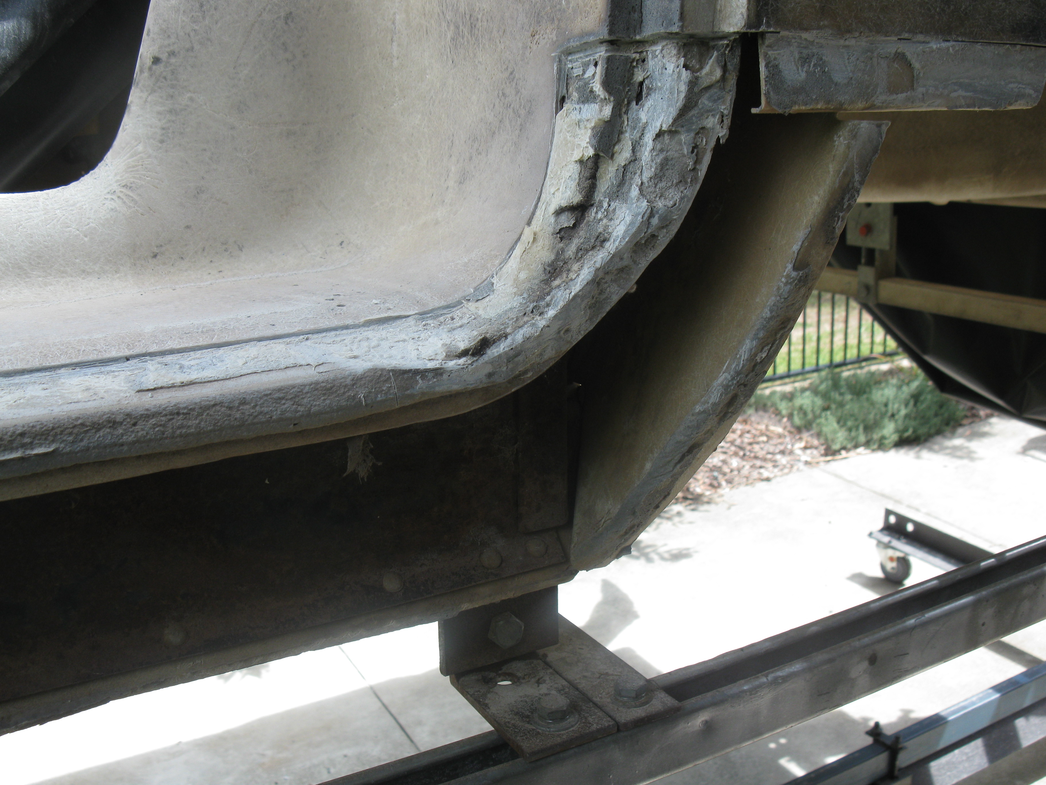
Chip, I was in the same situation several years ago with my 60 - good body but bad metal - including the frame and metal body reinforcements. As mickatbp's picture in post # 21 shows, there is a steel reinforcement inside the rocker panel. It is bolted through the body to the inner structure on the front. On the back, just behind the splash shield is a bracket:
It is riveted to the body on two sides and also riveted to the steel reinforcement. I used 1/4 X 20 bolts instead.
In the passenger compartment are the brackets you show in your one picture:
The two brackets effectively sandwich the fiberglass at that location and provide structural support from the front body mounts to the back mounts:
Finally, the "hidden" bracket is rivited to the external body mount (don't have a picture of that one)
I happened to find the "hidden" ones in a junk yard. Not sure if they're made by anyone.
Rod
I did not know about the hidden brackets, I did some research and it seems Vette products makes all these metal parts. My gut tells me to start ripping fiber glass and repair/replace all of this, then I stand back and look at the fact that none of the body glass has been affected by it, going crazy. Chip
Yeah project creep, I will study all these pics and go for it , more pics would be cool. I think now is the time to do it. All my body glass is good but the metal parts have rusted from sitting for 40 years in humid garage. Chip
The other ones to check are the braces behind the kick panels. Check the bases and if they are rusted through. I think I might have one brace for the area where the dimmer goes. I cannot remember. I might have the 'hidden one' shown above too. Let me know. I would be happy to get it to someone who can use the parts.
Jim, my braces behind the kick panels are still solid with just surface rust. I will clean them up and paint. I'll keep your hidden bracket offer in mind once I decide exactly what I'm going to tackle at this time. Thanks Chip
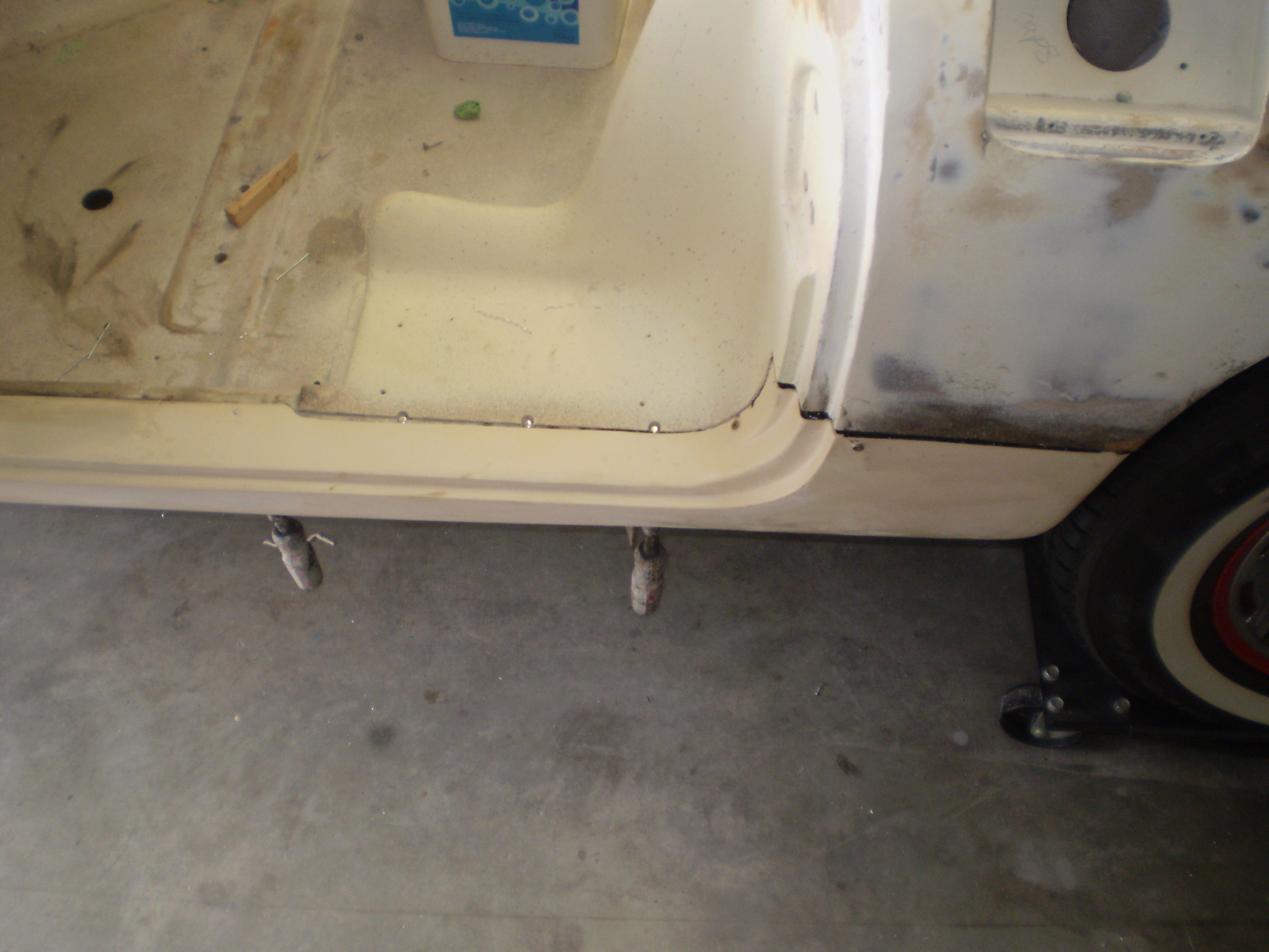
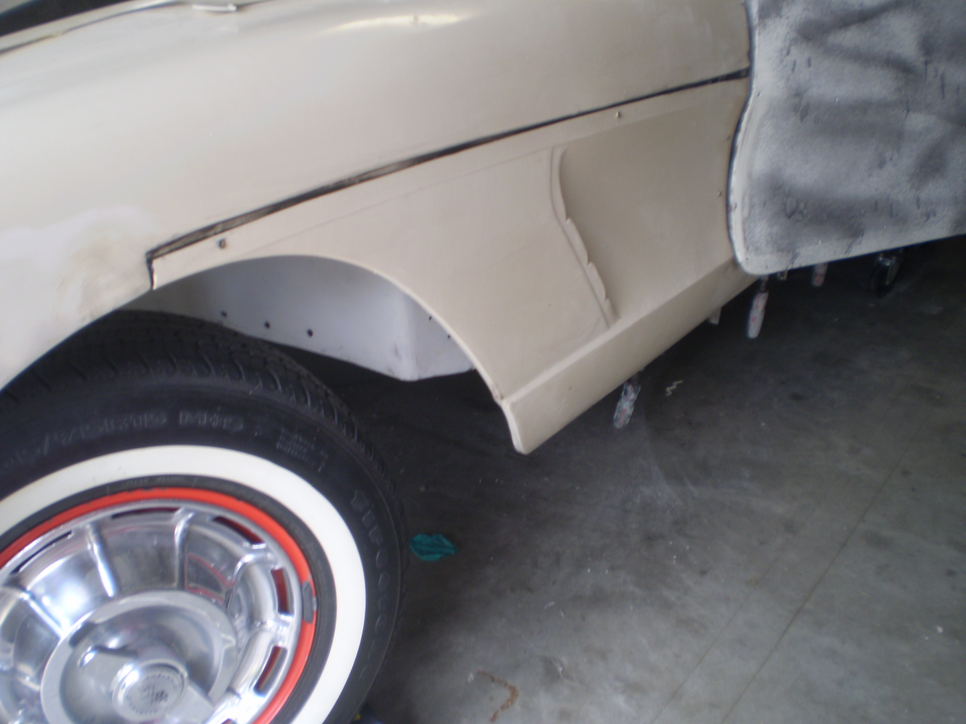
Id remove the small panel on Left and Right sides just in front of the rear wheel as this is an easy enough panel to remove which will then allow you to survey how rotten the hidden steel parts are; you may be surprised (here's hoping) and it may be okay. Removing these small panels will also give you access to then replace the rear inner mounts that are rotten on both sides and you can put bolts through. The front mounts are a different story and you need to cut a smallish hole to get to the underside of these if you plan on using bolts to secure the new front mounts in position.
Of course if the hidden brace is cactus then remove the side panel and replace the brace.
I pretty well much managed to get my panels off as one piece with only a few small penetration holes through them in a few spots. What you need is a dozen or so putty knives that are very thin bladed (1 inch or narrower in blade width) and that the steel for the blade goes all the way to the back of the handle (so when you hit the back with a hammer the force is transferred through to the blade rather than shatter the handle), a hammer - not to big so you can control the force you apply, a die grinder and some small course burrs to remove the glue in all of the seams before you try and remove any panels (and to clean the glue off later).
Ensure all paint is removed so you can easily see the glue seams(made easy because the bonding glue is black in colour). Remove all glue that is bulging out between any butt jointed seams so that the putty knife blade doesn't slip off its intended location. Die grind out all glue down to the depth of the glass of the panel underneath with a square ended burr where ever you can. then gradually at close intervals start hammering in the putty knives (all a little bit at a time) until the seam gives way, do the underside of the kick panel first until this seam is open all the way along - you'll need to drill those rivets out first; then start on the top seam (I started in the middle and worked my way back to the B pillar end and then forward to the A pillar/hinge end). Don't rush it and you'll do just fine.
I used rigid box cutters rather than putty knives and sharpened the ends nice and thin as I could get these from work. Flex the blade so that it is wedged in the joint seam before hitting with the hammer otherwise you'll put holes in places you don't want them.
Some suggest using heat to soften the glue before trying to break the seam - that suggestion was of absolutely no help to me but may work for you. I tried a hair drier and a paint stripper gun, all that did was make it difficult to work at the removal process because everything was bloody hot.
Sounds like a perfect plan Mick, now that you verified that I can at least replace those rear inner mounts by removing those small panels is great! Like you say maybe I'll luck out and it's not so bad on the inside, either way a least I'll see what I have going on and go from there. If you have any other pics that would be helpful. I agree with you about using heat to seperate panels, I had to remove the fiberglass reinforcements under the floor to replace the nut plates for the seat tracks and the adhesive stayed hard as a rock but the fibergass softened and wanted to tear, I let it cool down and seperated it cold with putty knives. Chip
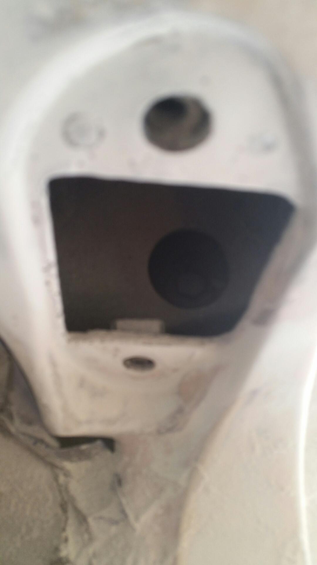
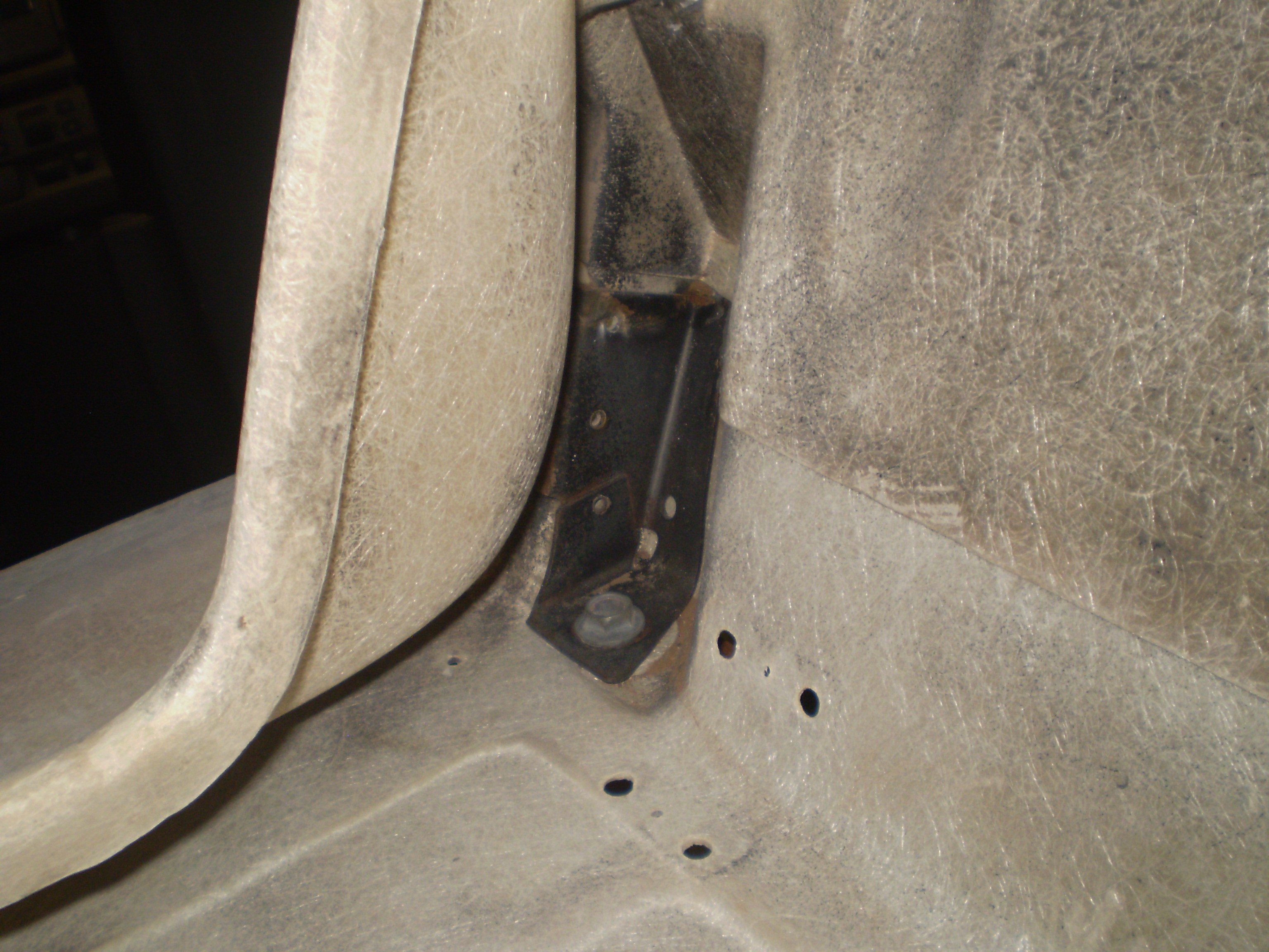
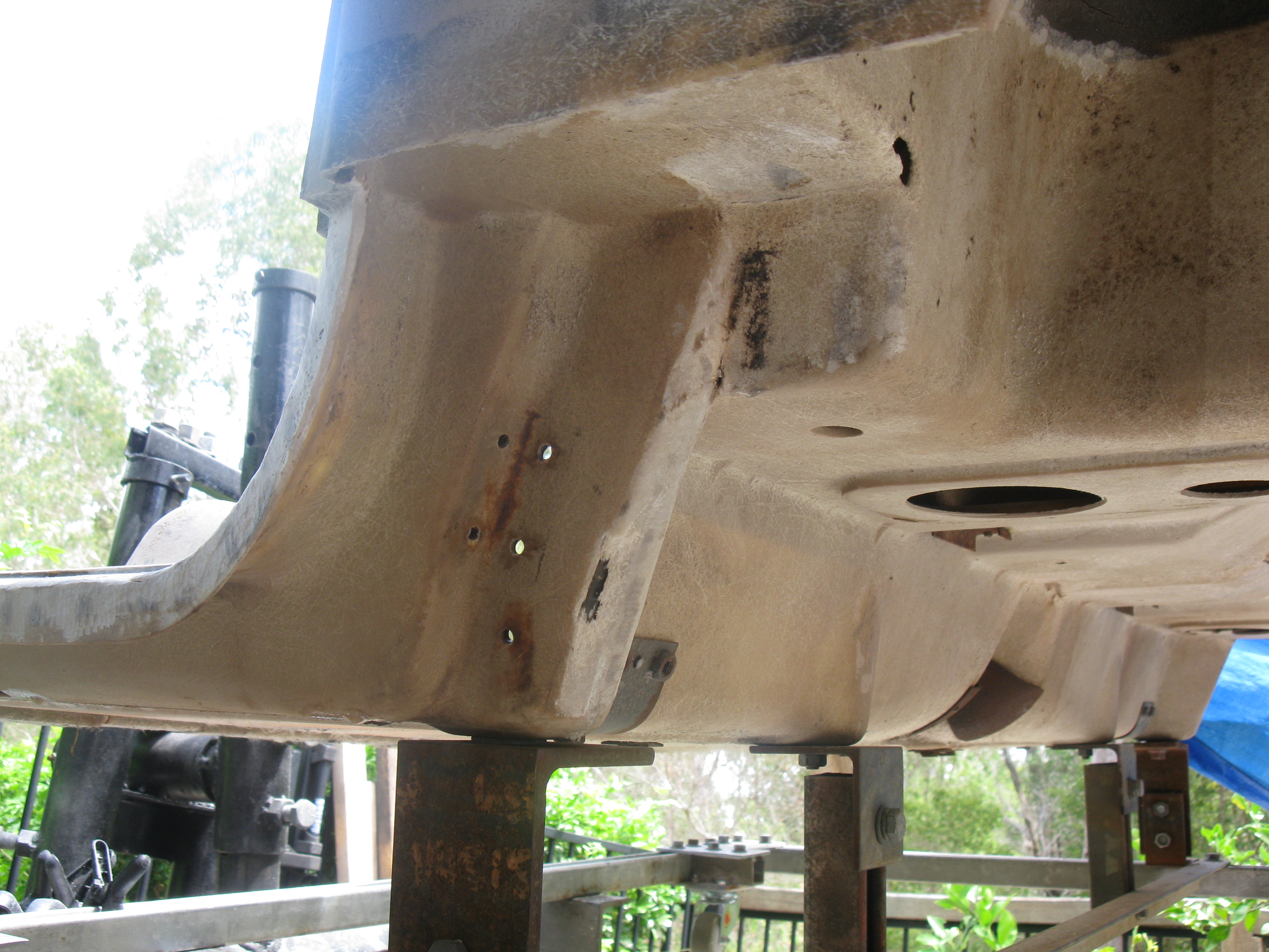
So the small rear panel came out easily with out damage using just putty knife. The first thing to fall out was the hidden mount, the sheet metal is not good and there are more acorns, I must have removed 5000 acorns from this car. here is a pic. Chip
So the small rear panel came out easily with out damage using just putty knife. The first thing to fall out was the hidden mount, the sheet metal is not good and there are more acorns, I must have removed 5000 acorns from this car. here is a pic. Chip
Well if nothing else you know where you are at (sadly) but on a positive note you are doing something about it. Once you get over the mental anguish of having to do more work than you had initially planned it is pretty straightforward as long as you take a sensible approach and leave 'Bubba' in the toolbox.
1. If you are going the hole hog then gently remove the small FRP press moulded pieces that run across the body and hide the seat mount nut plates.
2. Remove the FRP pieces on the underside that run parallel to your rotted braces. This will give you access to the front hidden mount section but from memory I don't think you can get to the nut in the front underside of this mount; at least not once you fit the new brace.
3. I think you could drill upwards to remove the rivets that hold the brace on the door jam as most of your brace metal is gone. I'd use a sharp wood chisel to knock off the mushroomed ends of the rivets so drilling is as accurate as possible. This will also then show you where the rivets are looking from the top of the jam down so you can use your die grinder to clean the filler/glue around the rivet heads and remove what is left of the rivet after having drilled them out.
4. This should at the very least give you a very good indication of whether you need to cut a hole on the outside panel in line with the front mount nut or remove the entire panel.
Take your time as you have done so far to minimise damage to pieces you plan on reusing.
As I said I got all of my hidden mounts and those two braces hot dip galvanised so that future rot won't occur and I don't have to (or any future owners) worry about that job ever again. Easy if you have a galvanising plant 15 minutes away as I do.
Before you refit you new braces, you have an opportunity to bond some small backing pieces where you have cut your front access holes so when it is all together you can just bond the pieces you cut out back into place.
Mick, yes going "hole hog", do it once do it right, both sides. I ordered all the metal parts, but won't do anything until they arrive and I can see what it's supposed to look like then plan my method of attack. From your pics, it looks like removing outer panel is the most straight forward, with access to every thing. Also have to replace/repair DS FRP at front mount, its ripped as if someone tried to lift the body with out removing the bolts, I hope they are reproduced, it would be difficult to reconstruct. If you have pics of removal process of outer panel (bonding seams), or a pic of the panel after removal, that would help. Chip
Mick, yes going "hole hog", do it once do it right, both sides. I ordered all the metal parts, but won't do anything until they arrive and I can see what it's supposed to look like then plan my method of attack. From your pics, it looks like removing outer panel is the most straight forward, with access to every thing. Also have to replace/repair DS FRP at front mount, its ripped as if someone tried to lift the body with out removing the bolts, I hope they are reproduced, it would be difficult to reconstruct. If you have pics of removal process of outer panel (bonding seams), or a pic of the panel after removal, that would help. Chip
Chip,
I'll see what I have on a camera but camera is currently at a mates place, will let you know.
Are you going to try and keep the side panels that you remove or replace them with new press moulded items. Was easy for me as I knew mine were stuffed before I started so had new next to old and marked seams location using the new panels as a guide. But the best advise I can give is get rid of ALL of the paint and undercoat near and around where you think the seams are as the bonding adhesive is black and stands out giving you a great guide as to where to start the panel removal process.
If you want I can email you photos, that way you can zoom in for greater detail. Email me at michael.stumpf@bigpond.com and I'll do my best to reply as soon as possible.
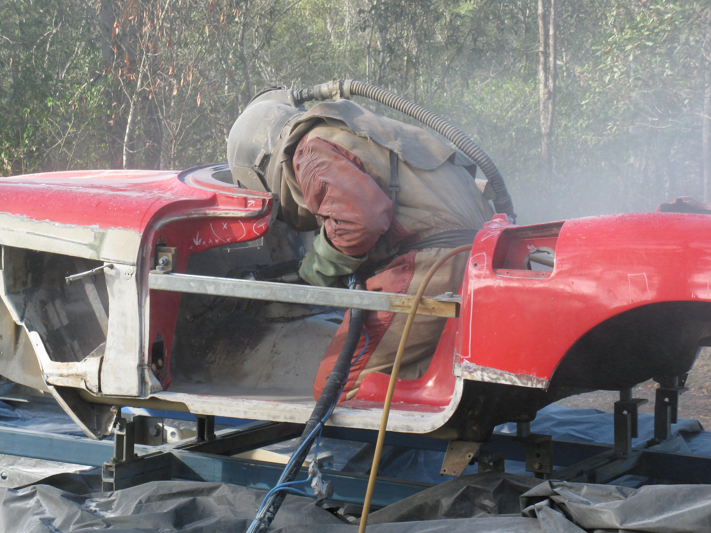
body mount and rail replacement photos - no particular order.
Chip,
I've found these photos which may be of some help to you. Probably have others but these will do for a start. If you need photos of specific areas let me know and I'll look further. If you want me to email any to you so you can zoom in.
Regards
Mick
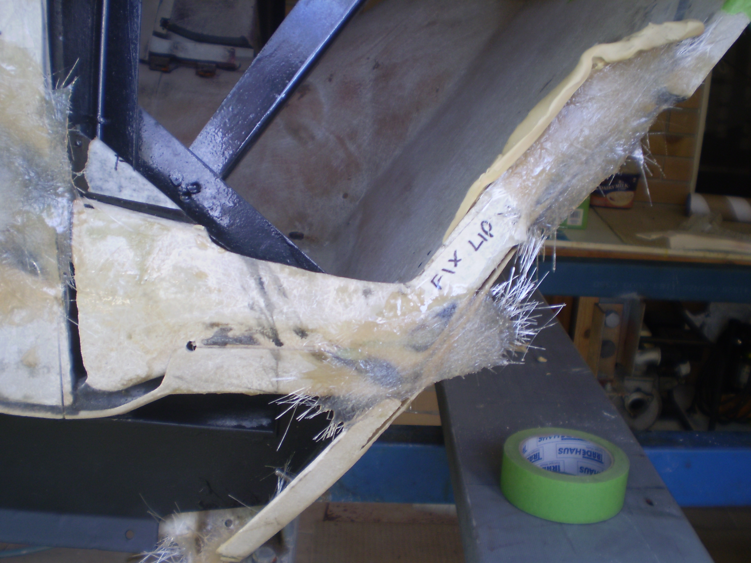
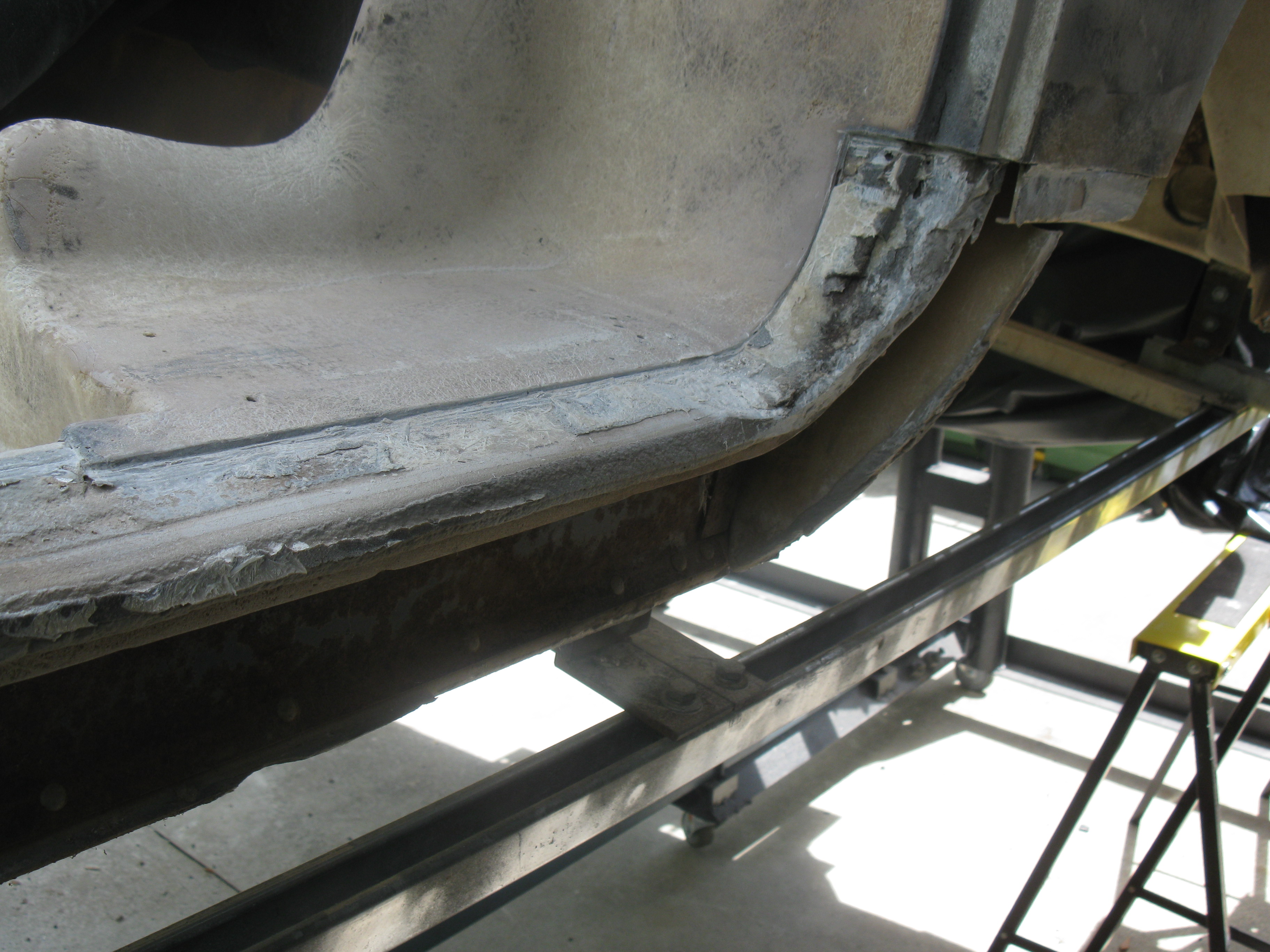
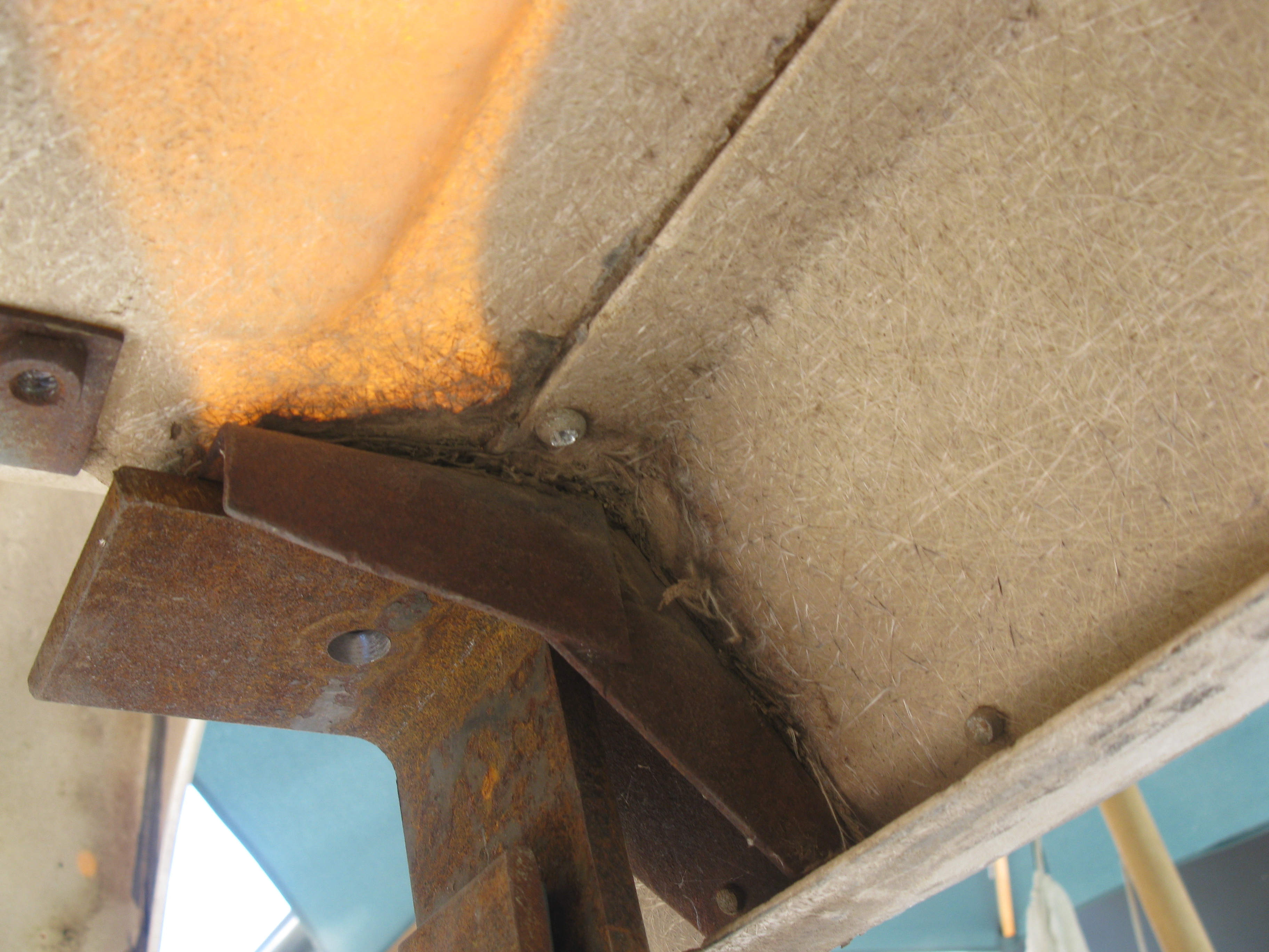
This photo shows the front 'birdcage' but more importantly that you will sustain some minor damage to the bonding panels inside when you remove the outer panel as it is a difficult area to get to and there is a lot of adhesive around this area that you need to break.
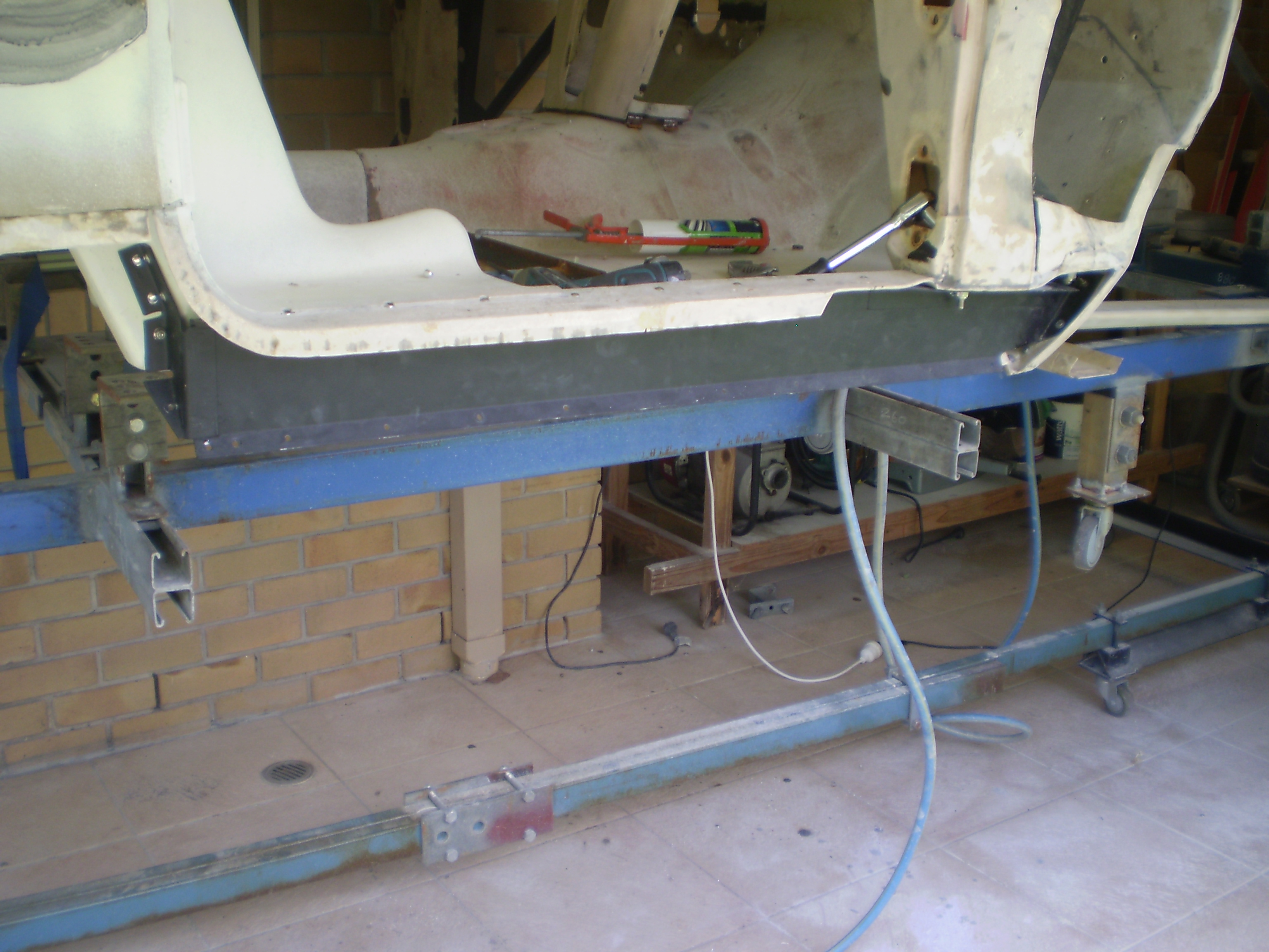
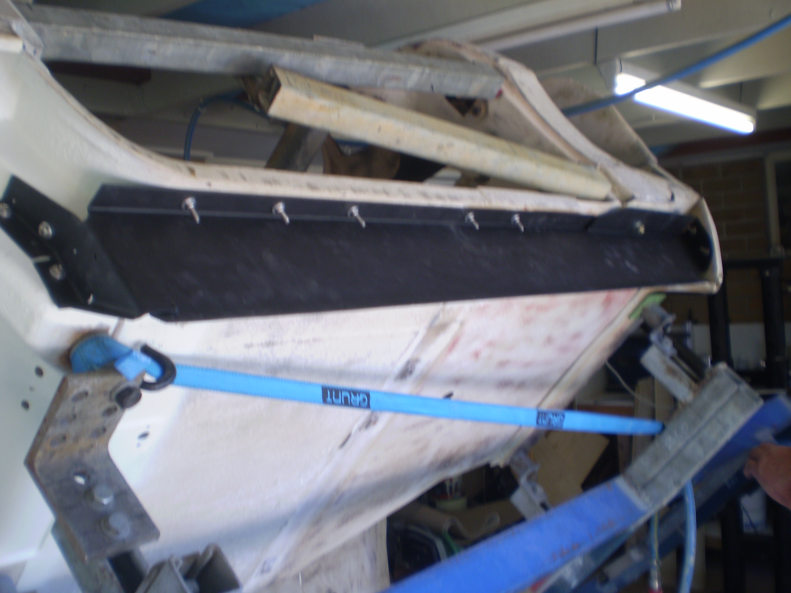
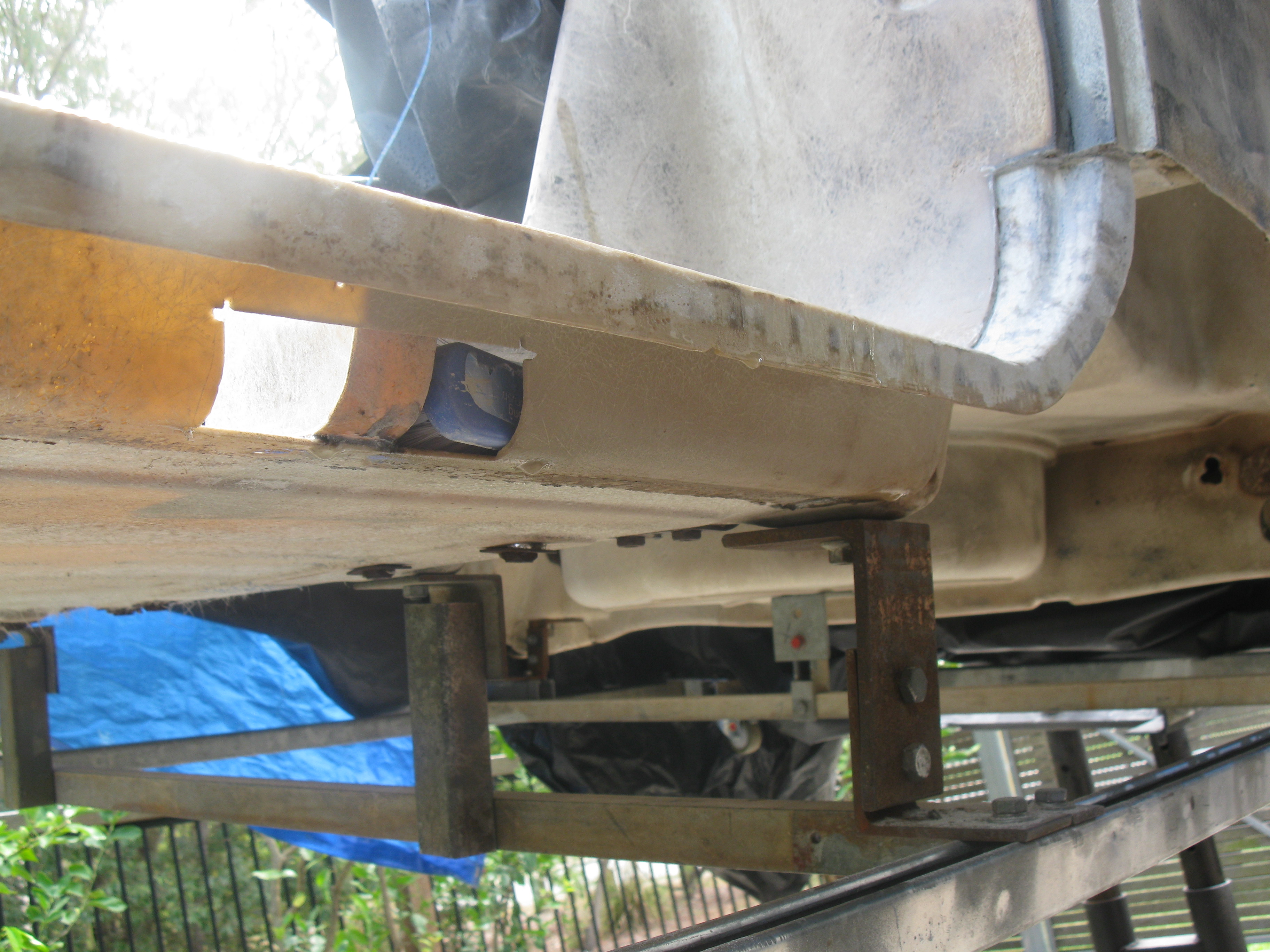
This photo shows the refurbished rails in place with all of the top rivets fitted and most importantly the the two front screws the hold the birdcage to the brace. I enlarged these holes and used stainless bolts as originals seems pretty small in diameter and were very corroded with good size SS washers top and bottom to help distribute the load and lock nuts for piece of mind. I also used aluminium washers with the same diameter hole as the rivet diameter where possible (where they couldn't be seen) before I mushroomed over the tail to also help distribute the load. If you use washers a good tip is to hold the washer in position against the FRP surface before you start the deform the tail of the rivet otherwise the washer gets stuck half way up the stem of the rivet.
Showing outer front mounts in position with finished rivets. Rivets are pretty easy to do and look nice when redone. I also used Sikaflex behind these outer mounts to seal them off as there is a bit of a gap behind them when positioned which when full of crap will encourage corrosion (under the black paint these mounts were also hot dip galvanised). The top two rivets of these front mounts are the longest required anywhere on the body (I believe) and the originals pretty well much didn't do anything as they were way too short.
This photo just shows the rear seam and rivets. I initially used a spot weld remover bit from the top to gently cut down to the depth of the rivet head, be careful doing this as you can easily drill a LARGE hole all the way through you glass panels.
This shows the outer rear mounts with the rivets removed. Note, there is a FRP washer under these mounts to minimise the air gap between the FRP body and the mount and if not reused will cause the inner mount to be deformed when the body is screwed to the chassis
This and the next photo show the rails in position and you will note that I use screws in every hole initially that were tightened down and I then took each one out one at a time and replaced it with a rivet which I deformed before going on to the next one. At this stage it is probably important to note that in some instances the rivets were too long and to get a nicely deformed 'mushroomed over' tail you only need to have about 3mm sticking out. Can be easily cut off with side cutters and though the cut is more like a 'pinch' than a straight cut it is not noticeable once the mushroomed end is formed.
This photo just shows the front seam and if you don't want to go to this level of trouble then I'd just remove the outer panel in line with the top of the front outer mount. Will be much easier and you sustain less damage to the bonding strips behind. I only removed my panels because they were hand laid up by what must have been a five year old with no instruction because they were utter crap.
I used an automotive Sikaflex between glass and metal in most areas to seal and to reduce any possible squeaks that may occur due to rubbing and flexing between these surfaces. It can be easily wiped off with acetone and can be painted over.
If you want. I can supply you with the size of the rivets and the address from where I purchased them from in the US (can only buy in lots of 100 but you'll need a 'shed' load anyway) and then riveting equipment needed. The most expensive purchase will be the dollies and riveting sets (you'll need a few different profiles) and like I said a cheap air hammer from you local automotive shop will have you ready to go. You'll also need a mate to either man the rivet gun or the dolly. When you buy the rivets also purchase the correct size drill bits (a few spares) from the same location. And as I said earlier a straight and 90 degree die grinder with a couple of large course burrs (round end and square end) will see you make an easy job of it.
The advantage of using a die grinder is the dust created is quite course more like sand and is less air born because asbestos was used in the original bondo for strength and as a thickening agent. They say it safe as it is encapsulated in the resin but be safe, create as little fine dust as possible and wear a good dust mask otherwise
If you leave the rivets too long they just bend over like a nail rather than deform, about 50% of those in my rails were just bent over rather than mushroomed over. If you move the dolly in a small circular motion as you use the gun you'll be surprised at how nice a mushroomed tail you can form. And if it looks like crap then its easy to just drill the rivet out and do it again.
Best of luck, give me a bell if you want the contact details and any more help. I found the riveting to be quite a soothing and satisfying process and lots of smiles between me and my helper as we got them right and became better at the process.
Reversed this bottom line of rivets when I put them back in with the head of the rivet on the underside and the mushroomed end facing up .... much stronger than original rivet application.
Top rivet, drilled a small pilot hole so I could see where they were hidden on the top side. I small air drill id great as is nice and compact to get in to small locations. Also the bottom rivets, where you can see the tail, I turned these around when I put new rivets in so the tail was mushroomed over against the metal rail to give a much stronger bond. You can see by how little the original rivets are mushroomed that they must have had trouble getting access to mushroom over the ends properly. A good rivet set and dollies will avoid this problem when you do it.
These two photos; Bondo cleaned off and a little bit of damage to repair.
 02-03-2016, 05:53 AM