[C2] Sidepipes vs. under the car exhaust power comparison
 10-24-2016, 08:17 PM
#41
Safety Car

Adding a very large chamber ("box") directly behind the collectors is a fairly well known trick to attenuate/eliminate the reflected wave that is normally created at the collector end. The only problem with it is packaging.
 10-24-2016, 09:19 PM
#42
Burning Brakes


i whole heartedly agree sidepipes are music to my ears. I have short racing baffles w fenderwell headers . 400 amp speaker for cds drowns out the xpwy traffic noise. I would fight to keep them
10-25-2016, 03:27 AM
#43
Team Owner

Member Since: Nov 2005
Location: Beach & High Desert Southern California
Posts: 25,500
Received 2,345 Likes
on
891 Posts

Recognition of the comparable magnitude of momentum effect compared to organ pipe effect, applying a vacuum at the exhaust valve, is difficult for most people to understand intuitively. An illustrative example is feeling the velocity pressure at the outlet of a air pressure hose compared to an air horn. The horn is loud but does not move mass more than a few cm away from the outlet. The air hose airflow mass at velocity mows over whatever is in the path of the outlet much further.
Air in motion wants to stay in motion, and airflow motion leaving the exhaust valve wants to keep moving away creating a strong vacuum behind the valve. The mass of this airflow in motion is much greater than that subject to organ pipe effect, the mass of the airflow in the entire contained headpipe compared to the mass contained in the rpm tuned half-wave subject to the pressure wave vacuum.
In the H-D example the higher velocity of the smaller headpipe produced more momentum than the bigger headpipe (since mass was nearly equal). When the airflow mass of the collector was added it enhanced the momentum effect at the collector velocity sweet range. Combined effects complement the best of both airflow masses.
In SWC Dukes research the airflow friction losses exceed the momentum effect above .3Mach or 400 ft/sec, why the simplified rule is to design the headpipe diameter for under 260 ft/sec.
The force needed to create a vacuum behind the valve requires mass and acceleration of the mass (deceleration of the exhaust gas from 260 ft/sec to zero velocity every other crankshaft revolution).
Cup your hand over the shop vac hose and tell me if tuning for resonance will have a noticeable effect compared to the vacuum force magnitude already present from the untuned momentum effect you immediately feel? Double the hose length to experience excessive friction loss exceeding the added mass benefit as you feel less suction.
Dont overthink into the point of diminishing return.
 10-25-2016, 08:56 AM
#44
Race Director

Thread Starter

Member Since: May 2000
Location: Redondo Beach USA
Posts: 12,487
Received 1,974 Likes
on
1,188 Posts

The purpose of an exhaust box is to simulate the atmosphere (which marks the end of the "tuned" part of the exhaust system) in chassis layouts that require additional pipe length to safely clear exhaust gas from the driver and car.
Since Sprint Cup engines turn up to 9500 RPM, they need relatively short primary pipes (say about 24-26") and collectors (say about 18-24"), so the "tuned" part of the system ends about under the driver. The large exhaust box simulates the open atmosphere, and then two large diameter pipes route exhaust from the box to a safe exit on the RH side of the car, just forward of the rear wheels.
Mid/rear engine cars typically don't need exhaust boxes because the tuned part of the system - primary pipes and collector - is long enough to safely route exhaust gas to the back of the car.
Duke
Last edited by SWCDuke; 10-25-2016 at 09:19 AM.
10-25-2016, 09:26 AM
#45
Download the pdf and we can compare. Look at page three, but ignore the annotation about headers and mufflers. This configuration had the OE manifolds routed into the 3" dyno exhaust system with no mufflers.
Now let's look at the two tests on page 1 and 2. These were back to back tests within about five minutes and the exhaust system consisted of the OE manifolds and full OE sidepipe system that routed to the dyno cell exhaust system with no downstream mufflers. The A/F data does not appear to be valid, so ignore it.
Now we can get some insight into how restrictive the sidepipe system is compared to the under-the-car exhaust.
About half of this net-gross difference is the lower air density correction of SAE net compared to STP used for SAE gross, and the rest is the exhaust system and front end accessories.
Given the above the under-the-car exhaust system pumping loss is about 19 HP or about 5.3 percent.
Sidepipes ate up 39 GHP on the L-84, which is about 11.8 percent, so we can conclude that sidepipes cost about double the parasitic pumping power as the under-the-car system, which is significant!
Duke
There are others of us who prefer the sound of the N11 exhaust. The sidepipes to my ears are too shrill/boy racerish compared with the deeper menacing sound of the N11 off-road under-the-car exhausts, especially with the big block cars. To each his own, but I like the idea of better sound AND more power.
10-25-2016, 11:05 AM
#46
Tech Contributor
Member Since: Jun 2004
Location: I tend to be leery of any guy who doesn't own a chainsaw or a handgun.
Posts: 18,363
Received 771 Likes
on
553 Posts
The box isn't there to attenuate or eliminate the reflected wave, it's there to facilitate/tune the reflected wave's timing to arrive back at the exhaust valve at the correct time (and specific RPM) to put a low pressure signal at the cylinder during the overlap period to enhance the intake flow into the cylinder, which in most cases has the opposite condition of residual cylinder pressure being higher than intake manifold pressure, causing reversion flow. This tuning requires that the box be placed at a calculated distance from the exhaust port, which is a well known packaging (and noise containment) challenge.
10-25-2016, 11:38 AM
#47
Race Director
Thread Starter
Member Since: May 2000
Location: Redondo Beach USA
Posts: 12,487
Received 1,974 Likes
on
1,188 Posts
Figure N-11. I don't have any data on base versus N-11, but there it is not much... much less than between N-11 and N-14.
Duke
Duke
10-25-2016, 12:16 PM
#48
Team Owner
Member Since: Nov 2005
Location: Beach & High Desert Southern California
Posts: 25,500
Received 2,345 Likes
on
891 Posts
The box isn't there to attenuate or eliminate the reflected wave, it's there to facilitate/tune the reflected wave's timing to arrive back at the exhaust valve at the correct time (and specific RPM) to put a low pressure signal at the cylinder during the overlap period to enhance the intake flow into the cylinder, which in most cases has the opposite condition of residual cylinder pressure being higher than intake manifold pressure, causing reversion flow. This tuning requires that the box be placed at a calculated distance from the exhaust port, which is a well known packaging (and noise containment) challenge.
It sucks to design and fabricate a true tuned headpipe and collector system, just to have the excessive pipe length downstream of the tuned collector muddle your effect. Downstream pipe effect is like tuning the tube length of a bugle for a particular person's middle C note, and then have a poorly tuned trombone cut into the trumpet solo and ruin the tone.
10-25-2016, 01:56 PM
#49
Tech Contributor
Member Since: Jun 2004
Location: I tend to be leery of any guy who doesn't own a chainsaw or a handgun.
Posts: 18,363
Received 771 Likes
on
553 Posts
True, in that the box eliminates any undesirable resonance tuning effect from pipe downstream of the box. The box decouples or eliminates effects from pipe downstream of the box, leaving only the focus of the headpipe and collector pipe resonance at the valve. Yes, because that's its function.
It sucks to design and fabricate a true tuned headpipe and collector system, just to have the excessive pipe length downstream of the tuned collector muddle your effect. Downstream pipe effect is like tuning the tube length of a bugle for a particular person's middle C note, and then have a poorly tuned trombone cut into the trumpet solo and ruin the tone.
It sucks to design and fabricate a true tuned headpipe and collector system, just to have the excessive pipe length downstream of the tuned collector muddle your effect. Downstream pipe effect is like tuning the tube length of a bugle for a particular person's middle C note, and then have a poorly tuned trombone cut into the trumpet solo and ruin the tone.
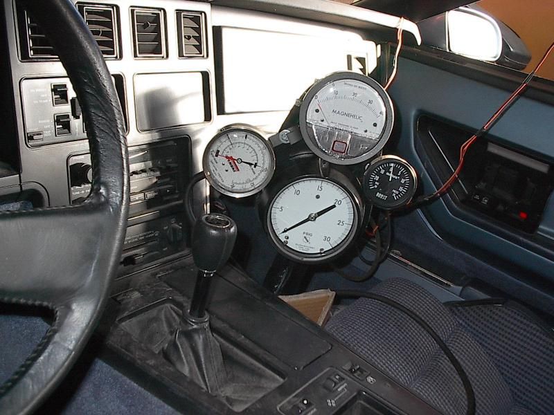
Here's my collection of pressure gauges I use on my cars to measure different positions in the exhaust system. This particular picture was during some measurements on my '84 where I had to measure the pressures on both sides of the turbo compressor and turbine sections. For the '69 I generally only need the top center gauge with a 0-40" H2O range.
 10-25-2016, 03:45 PM
#50
Melting Slicks

Here's more... About those dents in the header primary tubes, just exactly how much horsepower do they cost? I'm not surprised because the dents would have near zero effect on the +/- wave activity. Short video...
10-25-2016, 04:25 PM
#51
Team Owner

Member Since: Mar 2003
Location: Greenville, Indiana
Posts: 26,118
Received 1,843 Likes
on
1,398 Posts
Maybe a little off topic but this reminds me of my 400 CC Suzuki Moto bike I had in the early '70's. It had a tuned exhaust on it. The bike was very pipey! That means the 40 horsepower it was rated at was either on or off. Not much in between. The thing was a handful to ride in the woods with that power band. I miscued one day, jumped a big log and didn't make it all the way across and the weight of the bike and me came down on the exhaust pipe, just before it ran into the expansion chamber and closed the exhaust pipe about half size.
To my amazement, the bike was now civil to ride. The power band came on at a much lower rpm and still had more power than you (I) could use at the top end. I never fixed it because it was better.
To my amazement, the bike was now civil to ride. The power band came on at a much lower rpm and still had more power than you (I) could use at the top end. I never fixed it because it was better.
10-25-2016, 05:02 PM
#52
Team Owner
Member Since: Nov 2005
Location: Beach & High Desert Southern California
Posts: 25,500
Received 2,345 Likes
on
891 Posts
That's not been my experience. As long as the post-EPTB system is free flowing (minimal backpressure) and quiet enough for street driving, what's the problem? I always weld in an "upstream" pressure gauge tap into my exhaust systems to monitor the actual capability or shortcoming of my exhaust systems. I've never subscribed to the X pipe size is good for Y horsepower, as this "rule of thumb" completely ignores how long the system is, how many bends there are, and what the flow efficiency of the muffler is. (BTW, that's why I only spend my money on Dynomax mufflers, as they're confident enough of their products to publish the hp/flow versus backpressure results of their products. They're usually pretty quiet mufflers too.) The pressure gauge reading also tells me if the latest system design worked, and when it's time for an upgraded system when I've made engine component changes.
Here's my collection of pressure gauges I use on my cars to measure different positions in the exhaust system. This particular picture was during some measurements on my '84 where I had to measure the pressures on both sides of the turbo compressor and turbine sections. For the '69 I generally only need the top center gauge with a 0-40" H2O range.
Here's my collection of pressure gauges I use on my cars to measure different positions in the exhaust system. This particular picture was during some measurements on my '84 where I had to measure the pressures on both sides of the turbo compressor and turbine sections. For the '69 I generally only need the top center gauge with a 0-40" H2O range.
All you need to add are Total and Static Pressure ports (or a flow sensor array) and data logging to calculate Velocity Pressure and you can actually see the "organ pipe" pressure wave effect (and magnitude).
What you experience regarding pipe downstream of the box is correct, only backpressure from there back matters (less backpressure = more power).
I also agree with your comment on y-pipe sizing. HP based sizing is speculation at best, with no science to back it up other than backpressure restrictions if too small. A y or h pipe is also not an efficient decoupling device (as some claim).
Momentum and resonance V8 Header tuning design can be single stage (180 degree primary pipe into decoupling box), dual stage (bank primary and collector stages into common decoupling box), or three stage (try-y primary and collected bank secondary into third stage collector, followed by common decoupling box). Each stage that is collected and further from the valve provides less resonance effect, and less momentum effect, compared to backpressure friction losses.
Designs have successfully exploited traditional two stage headers into a common collected third stage resonance and momentum sized pipe, a pipe compared to a decoupling box, but the effect is negligible (and cost and sound quality suffer).
In the discussion comparing SBC ramshorn manifolds to headers the fact that the manifolds provide no primary pipe resonance or momentum effect is not mentioned (maybe too obvious, or misunderstood). The ramshorn manifolds provide minimal backpressure and only collected gas resonance and momentum tuning benefits. The header's primary pipe benefits are the sole difference, with momentum vacuum effect providing the higher magnitude of benefit (as long as the primary pipe is sized correctly).
The Viper story is instrumental, that sound quality often takes priority over performance (and an entire industry is built to fool the customer into believing otherwise).
The header dent test example reinforces the experience of momentum effect providing the majority of tuning benefit over resonance tuning. Too many people overthink the factors and ignore the consideration of magnitude of comparable effects.
A 1200 to 1500 dF exhaust gas motivated by by several hundred psi channed through an opening exhaust valve can contain considerable energy even when the primary pipe velocity is 0.25M. What works for exhaust does not directly apply to an 80 dF atmospheric intake track where the motivation pressure is limited to one bar or 14.7 psi.
10-25-2016, 05:40 PM
#53
Team Owner
Member Since: Nov 2005
Location: Beach & High Desert Southern California
Posts: 25,500
Received 2,345 Likes
on
891 Posts
Maybe a little off topic but this reminds me of my 400 CC Suzuki Moto bike I had in the early '70's. It had a tuned exhaust on it. The bike was very pipey! That means the 40 horsepower it was rated at was either on or off. Not much in between. The thing was a handful to ride in the woods with that power band. I miscued one day, jumped a big log and didn't make it all the way across and the weight of the bike and me came down on the exhaust pipe, just before it ran into the expansion chamber and closed the exhaust pipe about half size.
To my amazement, the bike was now civil to ride. The power band came on at a much lower rpm and still had more power than you (I) could use at the top end. I never fixed it because it was better.
To my amazement, the bike was now civil to ride. The power band came on at a much lower rpm and still had more power than you (I) could use at the top end. I never fixed it because it was better.
My son has a 66cc 2-stroke bicycle that he toys with. Many of his 15yo contemporaries have added reed valves and expansion chambers and cannot fathom why my son's simple constant cross section exhaust pipe piston port bike blows past them in the upper rpm ranges. His bike does not have the mid range response of their systems, but their fun is all top speed oriented. Tuning for momentum and resonance at 7000 rpm can make a difference when the competition is all in at 60 foot and you are just starting into the sweet range. A 2-stroke single is a great learning platform to explore fluid dynamic principles before introducing the complexity of multiple cylinders.
10-25-2016, 05:47 PM
#54
Tech Contributor
Member Since: Jun 2004
Location: I tend to be leery of any guy who doesn't own a chainsaw or a handgun.
Posts: 18,363
Received 771 Likes
on
553 Posts
Fantastic instrumentation.
All you need to add are Total and Static Pressure ports (or a flow sensor array) and data logging to calculate Velocity Pressure and you can actually see the "organ pipe" pressure wave effect (and magnitude).
What you experience regarding pipe downstream of the box is correct, only backpressure from there back matters (less backpressure = more power).
I also agree with your comment on y-pipe sizing. HP based sizing is speculation at best, with no science to back it up other than backpressure restrictions if too small. A y or h pipe is also not an efficient decoupling device (as some claim).
Momentum and resonance V8 Header tuning design can be single stage (180 degree primary pipe into decoupling box), dual stage (bank primary and collector stages into common decoupling box), or three stage (try-y primary and collected bank secondary into third stage collector, followed by common decoupling box). Each stage that is collected and further from the valve provides less resonance effect, and less momentum effect, compared to backpressure friction losses.
Designs have successfully exploited traditional two stage headers into a common collected third stage resonance and momentum sized pipe, a pipe compared to a decoupling box, but the effect is negligible (and cost and sound quality suffer).
In the discussion comparing SBC ramshorn manifolds to headers the fact that the manifolds provide no primary pipe resonance or momentum effect is not mentioned (maybe too obvious, or misunderstood). The ramshorn manifolds provide minimal backpressure and only collected gas resonance and momentum tuning benefits. The header's primary pipe benefits are the sole difference, with momentum vacuum effect providing the higher magnitude of benefit (as long as the primary pipe is sized correctly).
The Viper story is instrumental, that sound quality often takes priority over performance (and an entire industry is built to fool the customer into believing otherwise).
The header dent test example reinforces the experience of momentum effect providing the majority of tuning benefit over resonance tuning. Too many people overthink the factors and ignore the consideration of magnitude of comparable effects.
A 1200 to 1500 dF exhaust gas motivated by by several hundred psi channed through an opening exhaust valve can contain considerable energy even when the primary pipe velocity is 0.25M. What works for exhaust does not directly apply to an 80 dF atmospheric intake track where the motivation pressure is limited to one bar or 14.7 psi.
10-25-2016, 05:54 PM
#55
Team Owner
Member Since: Mar 2003
Location: Greenville, Indiana
Posts: 26,118
Received 1,843 Likes
on
1,398 Posts
The TM400 series bikes were a handful with the tuned pipe and trigger like centrifugal advance. A more restrictive smaller head pipe would add mid range momentum to soften the combined hit of chamber and advance, or a dent to aid restriction to soften without the momentum effect (and a progressive TS400 CDI advance could help even more).
 10-25-2016, 06:12 PM
#56
Race Director

. In conclusion, you need an expansion chamber somewhere in the system, & I believe the best location is around the middle of the system - call it resonators or mufflers. If you place mufflers/resonators at the very rear of the system, you'll do additional decibel reduction & possibly some tuning (depending on what you install).
Was that a conscious design/tuning choice, or just a default location determined by space availability? Perhaps that is what resulted in the N11 and N14 options?
10-25-2016, 06:15 PM
#57
Team Owner
Member Since: Nov 2005
Location: Beach & High Desert Southern California
Posts: 25,500
Received 2,345 Likes
on
891 Posts
(Bolded) I think we might be talking two different things here (or perhaps I'm just misunderstanding your point). The X in my previous post is just a place holder for any size pipe diameter (2.5", 3", 3.5", etc) and the Y is another place holder for whatever horsepower that the particular pipe diameter under discussion is supposed to be able to handle without choking the engine. I did not mean X or Y shaped pipes (although in an exhaust system discussion my choice of these placeholder letters was perhaps a poor one.)
I do agree, getting your point, the X vs. Y charts can be very misleading. They ignore the restrictive "minor losses" of tight elbow bends and the added friction losses required to redirect velocity pressure. Friction losses from tight elbows can quickly impact the predicted chart range for gas velocity and restrict the gas flow to a point that the next larger head pipe is better. This all goes back to your first point, less restriction is better.
10-25-2016, 08:30 PM
#58
Tech Contributor
Member Since: Jun 2004
Location: I tend to be leery of any guy who doesn't own a chainsaw or a handgun.
Posts: 18,363
Received 771 Likes
on
553 Posts
I always wondered why Corvettes (think C2s and C3s here) have chosen to install the mufflers at the very end of the system, as compared to other high performance cars of the same era that seemed to get a deeper tone with their mufflers at mid stream under the car.
Was that a conscious design/tuning choice, or just a default location determined by space availability? Perhaps that is what resulted in the N11 and N14 options?
Was that a conscious design/tuning choice, or just a default location determined by space availability? Perhaps that is what resulted in the N11 and N14 options?
Several years ago I fabricated a muffler and placed it under the passenger seat/floor area (to move the mass inside the wheelbase, and place it on the lighter RH side). Worked well enough, and satisfied my engineering desire to reduce the vehicle moment of inertia where I could), but I got tired of how often I scraped the muffler on uneven surfaces. Mid-mounted mufflers work well on four wheel drive pickups and Chevelles, but not on Corvettes. I went back to the original rear location, but have put the lightest weight (but still quiet) mufflers back there that I can.