
My Differential Rebuild Paper
 03-30-2008, 07:04 AM
#1
Safety Car

Thread Starter

1963-1979 Differential Rebuild
By Jeremy Smith
If you want the absolute best job out there, you can do it a few ways. One, you can send your diff to Mike Dyer (tracdogg2) or Gary Ramadei (GTR1999), OR you can build it yourself to their standards – which will probably cost you a little more because you have to buy the correct tools, pay for your mistakes (which will happen, trust me on this one), and build yourself custom tools…but you will have them for the rest of your life (and you can say that you built it!). I suggest you get in contact with them whether you plan on rebuilding your differential yourself or are having them rebuild it for you. I for one will no longer buy diff parts without first contacting Gary or Mike – they are straight up and only sell quality stuff.
I am writing this rebuild paper out of my own will. I do not intend to take any business away from the Corvette vendors out there – I am just a regular guy who likes to build stuff, that’s it. I’m only 18, and don’t even have the abilities to start a differential business. Sure I’ll help guys rebuild their diff and answer questions, but I’m not taking in work to compete with the vendors. I don’t have the time, money or even the facilities for that matter. This paper is designed to assist those who want to take on the task of rebuilding a diff by themselves.
If you have any doubt about your abilities to rebuild a diff, then send it out to get rebuilt by a professional. I am not liable for any of the work you do.
First Inspection/Disassembly of Unit
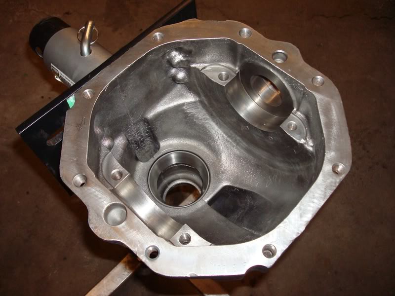
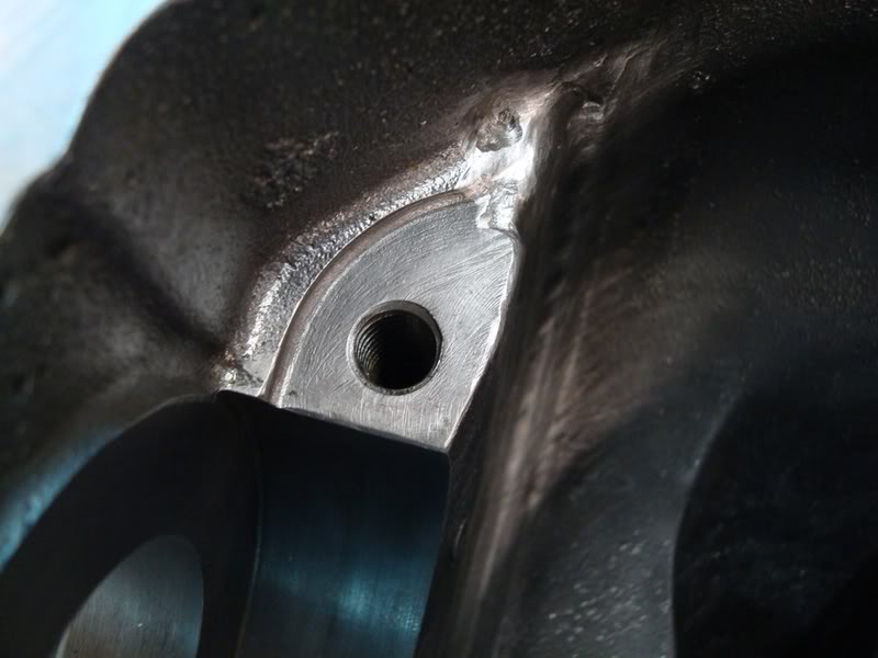
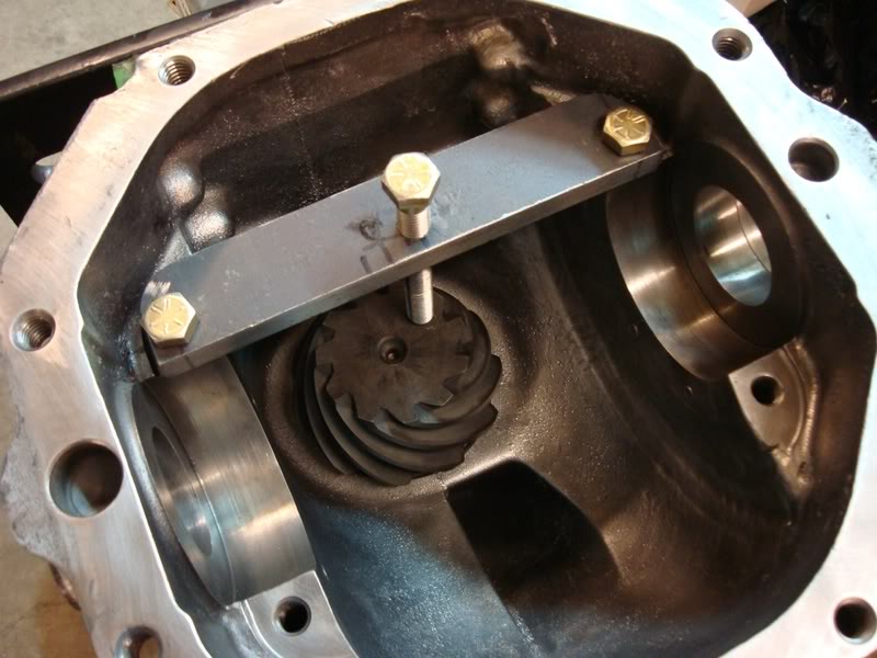
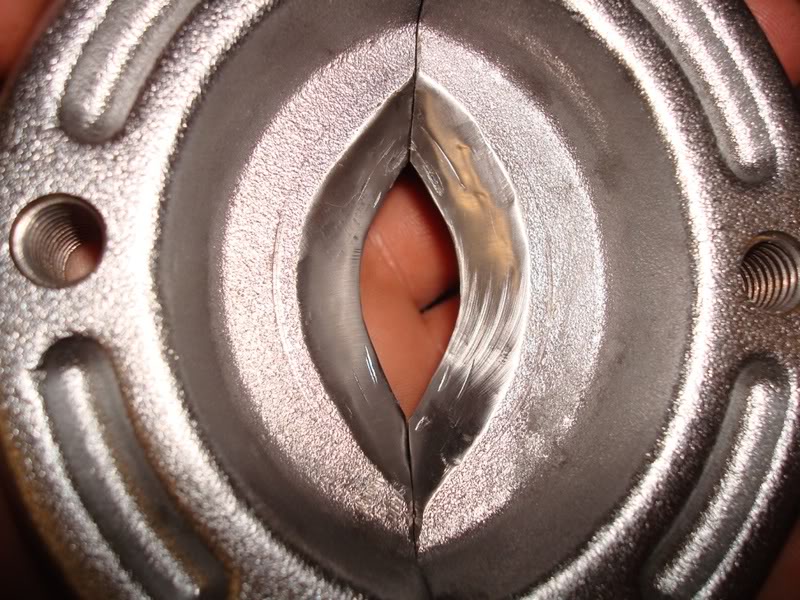
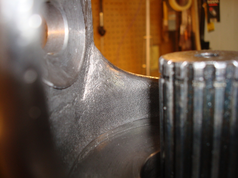
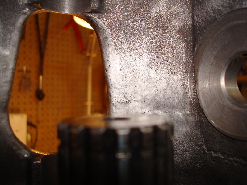
Once you get the diff removed from the vehicle, the first thing you want to do is go out and by yourself a cheap engine stand (3 wheeled) from Princess Auto (Canada’s form of Harbor Freight). The diff only weighs about a hundred pounds, so any engine stand will do. I can’t imagine anyone rebuilding a diff without this handy tool. It makes life so much easier, and reduces the amount of effort it actually takes to work on the thing; buy yourself one, it’s worth the money. I don’t have that many pictures from the beginning of the rebuild, so I will try to explain this the best I can. The first thing you want to do is mount the diff on the engine stand. Use two bolts in the strut bracket holes to mount it, and then place it on the stand. Unbolt the diff cover and then put an oil container on the floor. Turn the diff upside down and drain out all of the oil – turn the pinion a few times to help some of it pour out. Flip the diff back over and inspect the carrier and housing for any damage. Here are some pics of my damage. The previous owner must have lost a ring gear bolt and it chewed up the side of the housing – I used a die grinder and dremel to clean up the groove marks and make them baby smooth. I was lucky in that the bearing cap pads were in good shape otherwise.

When it came to the gears, I bought new Toms 3.73’s. I would not attempt to reuse gears unless I knew how they sounded before tearing them apart – even then I won’t reuse them. The reason being is because if they sounded like crap before you tore everything apart, they can’t be made any better, as they have already worn into the pinion mesh, and trying to repattern them to get less noise out of them is a waste of time…you’ll never get a consistent pattern. I’ll never reuse gears in my entire life, even if they sounded good, because I don’t think it is worth it. If you plan on reusing your gears, you need to measure everything before you take it apart – shims, backlash, gear pattern…everything. You need to get it in the exact same setup when you reinstall everything, or else the gears will make noise and howl. I am not going to go into much detail here on how to do this, as I don’t have this type of experience (I didn’t reuse my gears, so I didn’t have to worry). I know how to setup new gears, but I don’t want to give you the wrong info if you plan on reusing used gears.
Get yourself a cheap pair of snap ring pliers, and remove the side yokes. They may be ground down and stuck inside the posi case – you might have to use a dremel tool to get the yokes out. It takes some careful grinding, but they should eventually slip out of the housing.
Now, Gary and Mike mention to mark the carrier caps before you remove them. I tore everything apart before marking them and they got mixed up. I had to figure out which cap was for which side. Even if you do mark them before you remove them, you still need to refit them to the housing saddles – bubba may have been in here before and reinstalled the caps on the wrong sides. I refit mine using a special trick I learned from Mike over the phone – this guy is incredible, he knows everything. So does Gary – he also is a genius. It’s too bad they live in different cities, because they would make one hell of a diff shop. These two fellows also check the fit of their caps, even if they did mark them before removing them from the housing. For now, use a sharpie to mark the carrier caps, as they may not be on the correct sides. Gary and Mike are the only people out there that fit their caps – no diff shop will do this. To fit a steel bearing cap, you will need a bridgeport mill and a surface grinder, both of which I don’t own. To fit a stock cap correctly is very easy, and requires basic hand tools and patience. I will go into detail on this later on in the paper, as you need to first clean the housing.
If you want the best differential out there, then you will not be reusing any of the bolts and washers in the differential – you’ll be buying all new grade 8 bolts. They’re cheap, and they are easy to get…replace them. Get yourself a box and some plastic Ziploc bags. As you remove parts, label the bags and then put the bags in the box. This will keep you organized, even if you never touch the parts again. I never did this when I disassembled everything. My dad did most of the disassembly, as this was supposed to be his project (sorry Dad). I ended up taking it over as I am a much bigger perfectionist than he is; I also wanted to learn how to rebuild a diff. After reading all of Mike’s and Gary’s post, and reading threads by people who had their stuff rebuilt by shops or vendors (and then their setups being worse than before they had them rebuilt), I said to myself screw it. I’m doing a frame off restoration; why not suck all this information out of these two guys so I have it for the rest of my life. If I ever had something farmed out, it would be to Mike or Gary, both for their quality of work and because of all the help they have given me.
Okay, so now you have the bearing caps removed and stored away. Next remove the carrier from the housing. Try to keep the side shim packs together so you can use them as a reference point when setting up the diff. If you reuse your gears, this is critical. If you install new gears (like me) then it isn’t that critical as you will need to redo everything anyways. When using new gears, you need to make sure that the carrier is nice and tight in the housing before you preload each of the shim packs – I will go into more detail on this later in the paper, as we are not near this rebuild phase yet. Put the carrier aside for now, we will disassemble and inspect this more later.
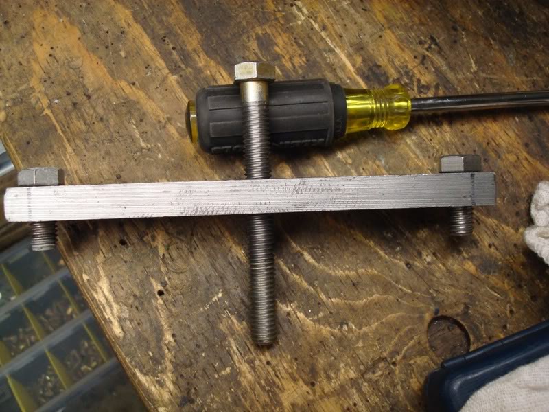
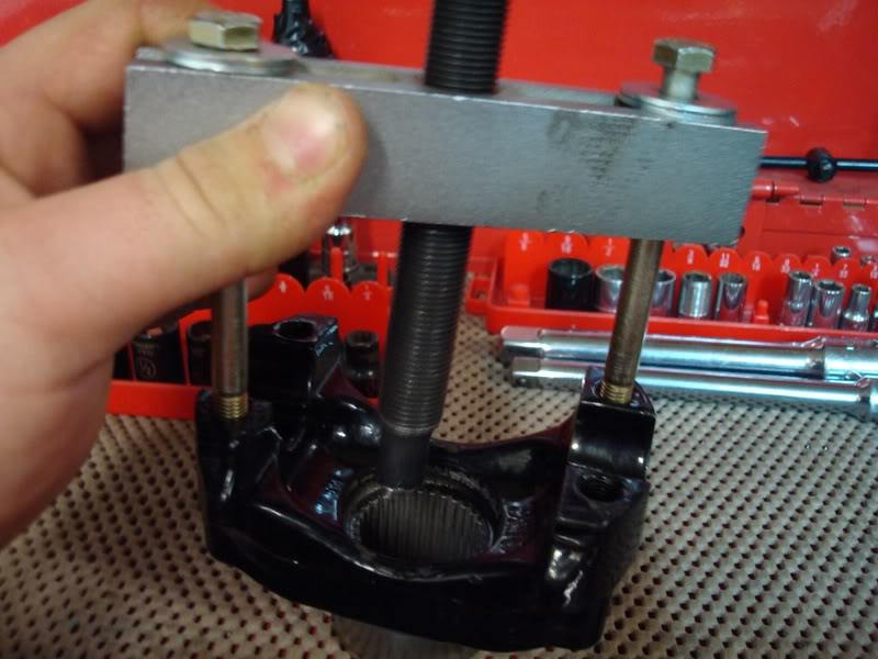
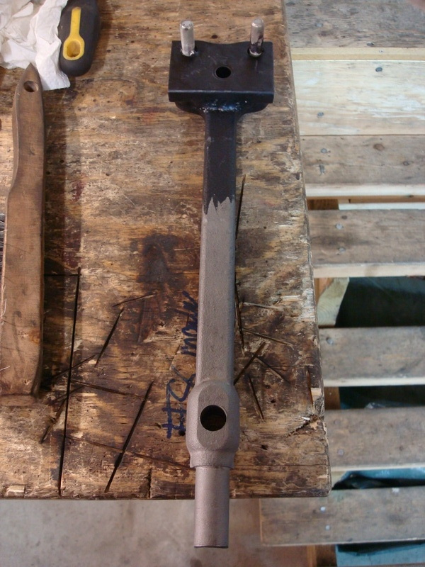
Now, if you are reusing your gears, you need to be extra careful that you don’t damage the pinion when removing it from the housing. Removing the pinion nut and then the pinion flange will let the pinion hit the floor (the outer bearing is not a press fit, it is slip fit). So for all you “used gear gurus” out there, now is the time to make your first homemade tool for the rebuild. You will use this tool a ton when you start assembling the diff, so put some work into it. It’s a pinion holder. All it is a piece of metal that has three holes drilled in it - two holes for bolts to go into the bearing pads, and a hole in the middle for a bolt. I tapped the center hole for the bolt, so you can tighten and loosen it to sit on the face of the pinion. You’ll probably not find this long of a bolt threaded this deep. I decided to use a tap and die set to make the threads go almost all the way to the top, not necessary, but I like to overdo things.
For the people out there that plan on using new gears, you don’t have to worry about hurting the used pinion. I for one didn’t care if the pinion hit the ground, because it was going to be used as a paperweight for the rest of its life anyways. So, when you remove the pinion nut and press off the pinion flange, keep your feet clear of its path (you don’t want any broken toes do you?). Here is what I used to pull off the flange, it worked great. It’s a tool from a bearing puller I bought, and two extra long bolts for the pinion flange holes. You will need this tool a lot when you setup the gear pattern, so you’re better off going out and buying one now. I think I saw a cheap small duty gear puller at Auto Value which might fit and work for this application, but you’d have to check to be sure.
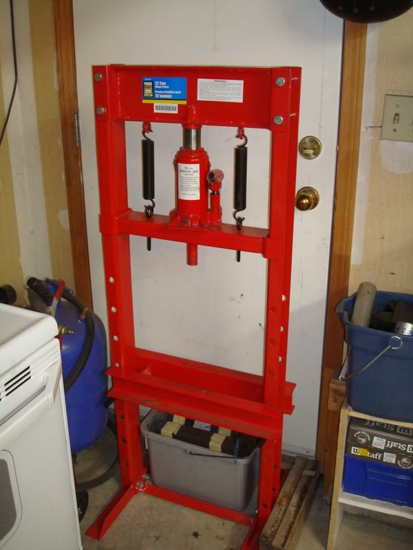
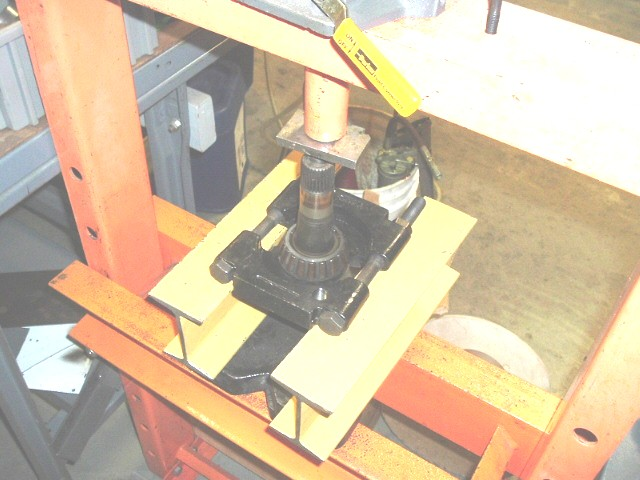
If your pinion is still stuck in the housing, do the following. Get your self a dead-blow rubber hammer and hit the pinion end while you hold your hand in the housing to catch the pinion. It should pop out with a little effort. Put the outer bearing in a Ziploc bag and in the box to keep you organized (you won’t be using that again anyways). Now it is time to remove the inner pinion bearing using a hydraulic press. Now, if you have a friend that is willing to let you borrow their hydraulic press for a few months, then do it. But if you just have a friend that says you can come over and use it whenever you want, then you will want to buy yourself a cheap one from Princess Auto (AKA Harbor Freight). The reason being is because it will get extremely old when you have to run over to his house every second day to press something else on…it honestly isn’t worth it. I hate buying tools from Princess Auto because they are always cheap quality and usually break or just don’t get the job done. I just couldn’t pass on this hydraulic press though, it was a steal. I think I paid $130 Canadian for the 12 ton press. If you were to build it yourself, that’s how much the steel would cost you to build the frame, so you are still saving yourself money. The hydraulic bottle will probably go in a couple of years, but you can get new hydraulic bottles from industrial places which are way better in quality, plus they are real easy to replace. I have used this unit to rebuild my trailing arms and steering box – it is great. I even used it to straighten out my steering bar, that saved me $100 alone. I believe Gary uses the exact same press, only he had to replace the hydraulic bottle because it crapped out. Other than that, this is a great tool (the diff is now finished as I write this paper, and the press is still going strong). Here is a pic of it:
To press off the pinion bearing, you’ll need a bearing splitter. I bought one from Princess Auto when I got the press, and did a little mod to it. The pinion bearing is pressed tight on top of the pinion shim, which is underneath the bearing. It is very hard to remove it without damaging the cage. It’s not that critical if you damage the cage on this bearing, as it will be replaced anyways. But when it comes time to the final setup, you might have to press off the good bearing to change the shim size, even if the setup bearings were perfect with a certain shim. What I did was smooth out the inside of the bearing splitter so it fit underneath the bearing sides a little more. You can see what I did in this pic:
Here is a picture from Gary on how to press off the pinion bearing (I didn’t have a pic).
Now it’s time to buy yourself a micrometer or caliper. I bought myself a decent one which is digital, and it’s pretty damn accurate. It’s nothing to be proud of though, its mastercraft brand (from Canadian Tire), which I absolutely hate. The next time I rebuild a diff or trailing arms, I will be buying myself a nice expensive Starrett Caliper and dial indicator/base. I think I paid $50 for my caliper and I always test it against my feeler gauges, which go all the way down to 0.0015. Measure the original pinion shim and take note of it. I think my original shim was 0.026’’.
The next step is to remove the pinion bearing races using a brass drift and hammer. Go slowly as not to gouge the edges of where the race sits (if you do, its not a big deal, as a dremel tool with metal cutting wheel works nicely to chamfer the edge again).
Cleaning/Painting
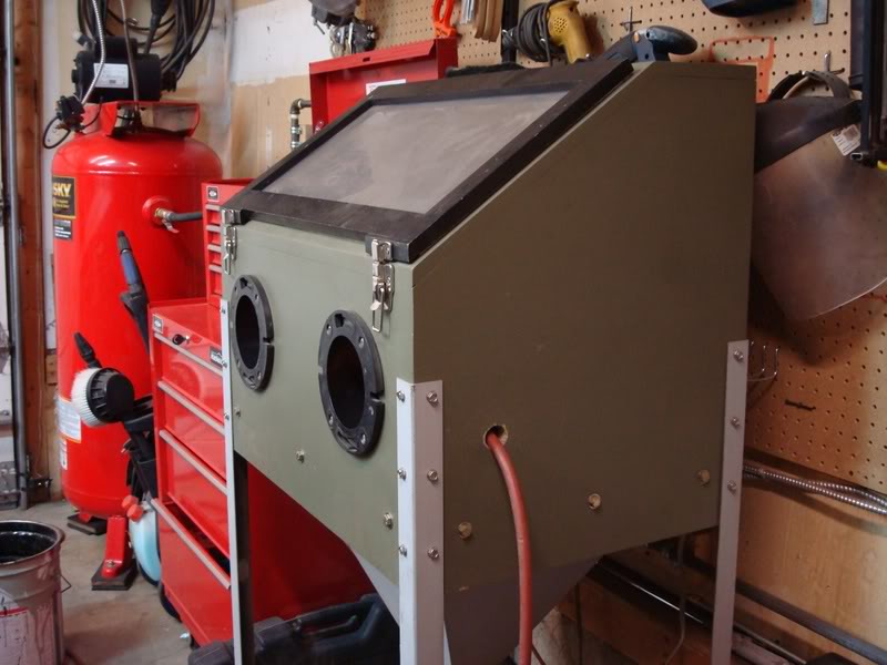
Now you have everything removed from the housing and it is time to clean it down to the bare metal. I had a bucket with a tightly sealed lid in the garage which fit perfect for the diff housing. I poured some gas, degreaser, soap and water into it and then mixed it all together. It will smell bad, so you need to keep the lid tightly sealed lid on it when it soaks in the garage. Place the housing in the mixture, put the lid on, and then let it sit for about 2-3 days. You’ll be amazed at how well this works. Hose the housing off with some water and soap, and it is down to the metal with minimal effort. The gas turns the oil into nothing…I couldn’t believe how well it worked. Then I taped off all the areas where sand could get into the housing, and sandblasted all the rust off. I built my own blast cabinet, which works great for projects like these.
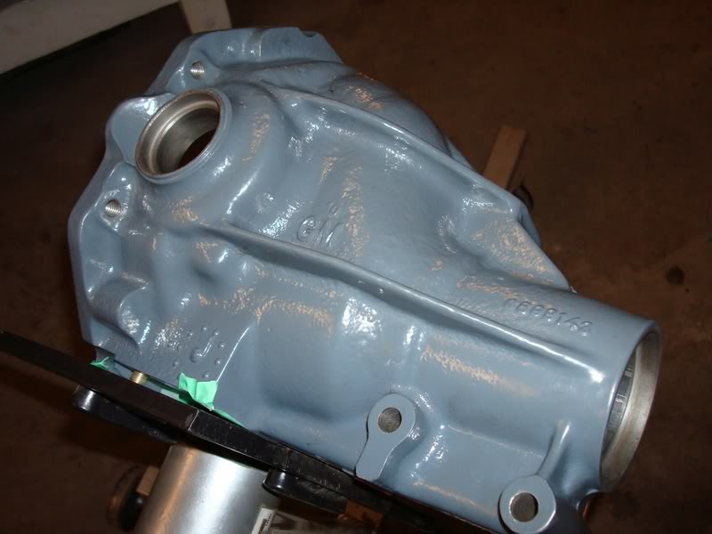
There are a few ways you can dress up the differential. The easiest and cheapest way is some spray paint from home depot. Lots of people seem to prefer the POR15 stuff, but I never really liked it ( I waited 3 days for a part to dry and it was still wet…after applying thin coats and following all the instructions down to the last letter). I think I may have got a bad batch. I decided to powdercoat my differential. The color is RAL7011:
Paint the rest of your parts at this time as well (side yokes, diff cover, front differential bracket…). If you sandblast your yokes, be careful that you don’t sandblast the area where the seal rides. I accidentally did this and I was not comfortable reusing the yokes (I also wanted to upgrade to the hardened tip ones made by Lonestar.
Posi Case Disassembly
The first thing you want to do is remove the ring gear from the posi case. Take one of your old side yokes and put it in a vise, then place the posi case on top of the side yoke. It works great as a work stand. Use an impact gun to remove the ring gear bolts. The ring gear is a tight fit on the posi case, and you will need to use a hammer with a block of wood to remove it from the carrier. Work your way around the ring gear. If you are reusing you gears, be very careful – the ring gear will eventually pop loose and will fall and hit your vise. I tuned my posi unit without springs, so I wasn’t too concerned with ruining the springs. I cut them out with a dremel tool and cutting wheel. Remove the two plates that the springs were wedged between. Okay, now you are ready to remove the posi pin. PLEASE TAKE NOTE OF THIS!!!!!!!! The pin is not a press fit; it is a slip fit which is held in place with a screw/pin in the carrier. I originally thought it was a press fit, and that I had to press the pin out. So, off I went to my hydraulic press, and pressed out the large posi pin – little did I know that the pin was held in place horizontally with another long pin, and I ruined my posi case. DO NOT PRESS OUT YOUR PIN!!!! First, you need to remove pin #3 in the following diagram…
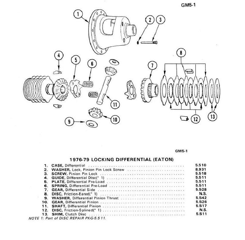
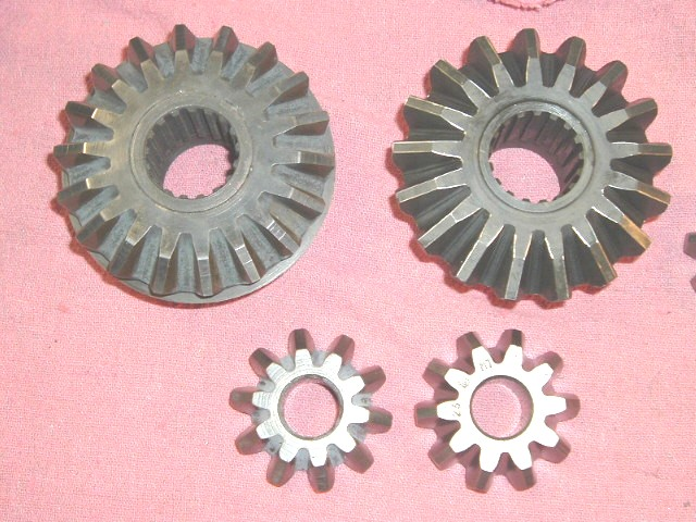
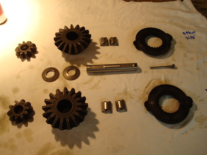
After you remove this pin, then you can slip the larger pin (#11 in the diagram) out of the housing using your finger. It is a slip fit, not a press fit, so it can be removed with little effort. I had to replace my posi case due to this one mistake – the small pin was crushed when I pressed out the larger pin, and the hole was elongated and broken…a really costly mistake on my part. Once you have removed these two items, you can remove the spider gears. Turn the posi unit by hand until the spider thrust washers drop out from behind the gears and then remove them (you won’t be reusing the thrust washers). Once you remove the spider gears (#10), then the top gear with its respected clutches and retainers will drop down and you can remove them from the carrier. All that is left to do is remove the bottom gear, which the side yoke is sitting on, and set it aside with its clutches and 2 retainers. You will not be reusing the clutches or retainers in the rebuild. However, if your spider gears are in good condition, then you may reuse them. There are two different types of gears – 17 tooth and 18 tooth. The 18 tooth gears are not as strong as the 17 tooth gears. Here is a picture from Gary regarding the difference between them (the good ones, and the ones you want, are on the right side). If you happen to have the 18 tooth gears, I’d replace them now. They are not as strong as the 17 tooth ones.
Degrease and clean the posi case, spider gears, large posi pin, and small pin/screw. Store the clutches and retainers in a zip loc bag. I also forgot to mention that the posi case sometimes has 2-3 shims on each side of the carrier – this was done by your folks at GM to pick up the slack in the case.
Carrier Inspection
You can reuse the carrier as long as it is not damaged and does not have any cracks in it. The large posi pin often elongates the machined holes in the carrier – if it is oblong, you will have to machine it for a larger pin or gears (I think Tom’s differentials does this), or replace the carrier. Look for any cracks and damage. One crack and it is toast unfortunately…don’t risk it, replace it now. All this work you’ll be doing will be for nothing if you have a bad carrier, as it will eventually go and ruin your entire diff.
Polishing the Posi Case
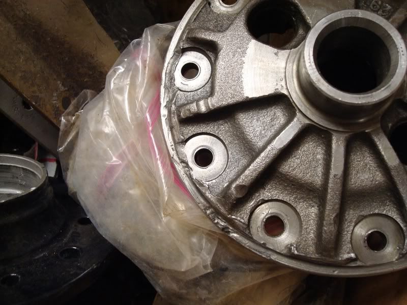
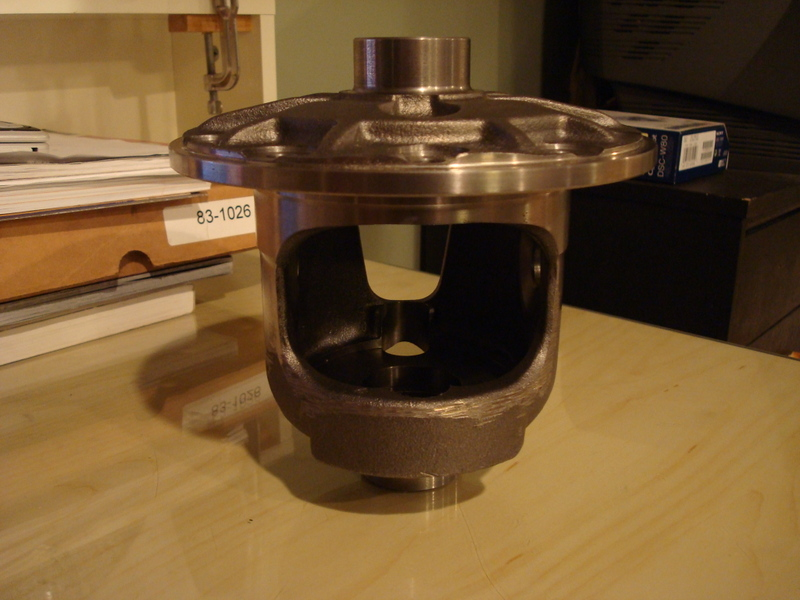
Now you are ready to start tuning your posi unit – it takes a lot of time to do, but it will be worth it in the end. The first thing you want to do is protect the surfaces that you don not want to polish (I used duct tape, as it is much more sticky than masking tape). Tape off the areas where the spider gear thrust washers ride – these areas are very important and you don’t want to ruin or scratch these. You will need a few tools for this job. I used a carbide burr with a dremel tool, die grinder and grinding stones, sandpaper, emery cloth and some roloc disks on a surface prep tool my dad bought me. The basic principle of this job is to remove all the stress areas from the casing – this will prolong the life of your diff, as well as make it much stronger than stock. If you look inside the casing, you’ll notice some “seams” from the casting process. You want to polish these areas as well. When you polish the windows on the carrier, you have to be careful not to continue the polishing past where the clutches ride, but you do want to carry the polishing inside the housing to the areas where the clutches don’t ride. I hope this makes sense. Here is what my new case looked like when I got it in the mail:
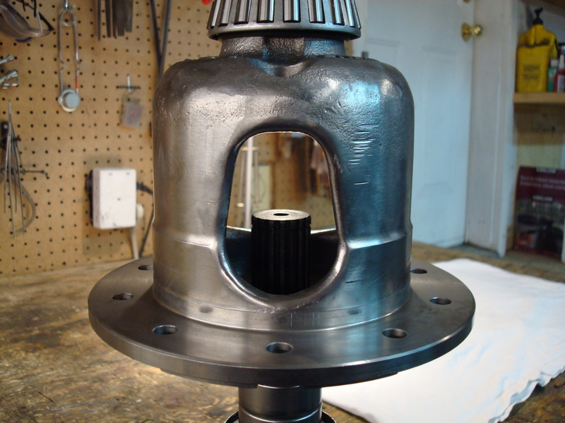
Here is the case after polishing (please ignore the carrier bearings, some of these pictures were taken after I decided to redo my work, and they are the best pics I have)…
After the polishing of the posi case is completed, you are ready to move onto the next step.
ARP Ring Gear Bolts
If you plan on using ARP ring gear bolts with your rebuild, now is the time to countersink the holes on you posi case. Gary touched base on this in one of his posts. Basically, what he found was there was a shoulder on the ARP bolts which prevented them from seating flat. The case I bought from Gary already had the holes countersunk, so that saved me from having to do it. A step drill might work to slightly countersink the holes too, but you'd have to ask Gary about that one. This step is mentioned in ARP’s instructions as well.
Beveling the Spider Gears
GM left a lot of slack in the original spring setup – the reason they installed the springs was to take up this slack by putting pressure on the side clutches. The clutches are designed so that they provide resistance when they are turned. By changing the spring rate in the posi unit, all you are doing is reducing side pressure on the clutches, which results in either more posi action or less posi action. They had to install springs because it was not cost effective to tune each unit by hand so there was no slack in the clutches – leaving the springs out would mean that the clutches would not drag across each other and provide no resistance. Thus, instead of the wheel turning at a different rate, it would be extremely sloppy and the spider gear tooth contact would be minimal. When both wheels are turning at the same rate, the 10 tooth spider gears prevent the clutches from turning. One spider gear wants to go left, and one spider gear wants to go right, and they lock up and turn at the same rate like a fixed axle. Thus, there really is no need for posi springs as long as you remove the slack GM left in the setup by shimming the side clutches properly. Too tight, and the clutches act just like the GM setup, and the wear on them will be excessive. Too loose and the spider gear tooth contact will be minimal and weak – and the clutches will not drag across each other providing a smooth motion. This is very time consuming, but it is worth it in the end. GM decided to try and fix their hammering issue by installing snowflake clutches to get more oil between the already stressed side clutches…now all this did was weaken them to the point that they would break.
You are going to be pulling the tolerances in very close, so you want to bevel the four posi gears’ edges. I used a dremel and a grinding stone attachment; just walk the grinding stone across the edges, don't apply any pressure (you want to break the sharp corners).
Parts
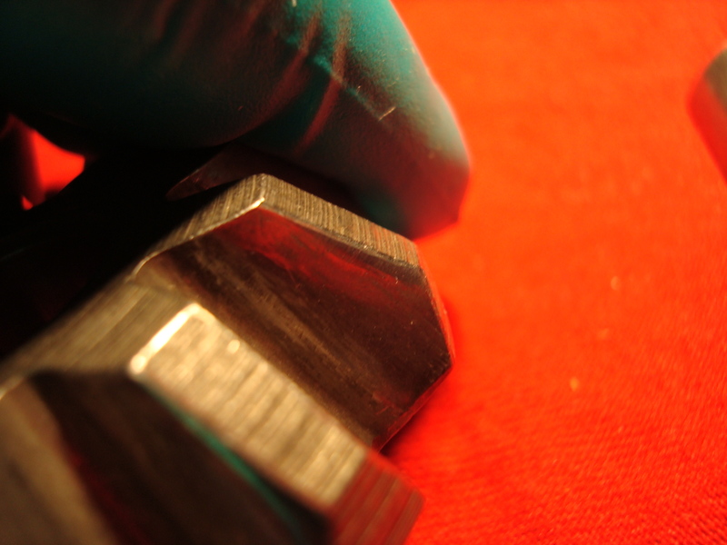
You will need to buy yourself a new set of solid clutches, a clutch shim kit, new clutch retainers and new spider thrust washers. The clutch shim kit comes with two sets of 0.010’’-0.045’’ shims in increments of 0.005’’. You will also need to get a hold of some GM posi additive for use when tuning the posi unit. Look over your crosshaft for any wear/tear. The OD of the top and bottom should be 0.747’’, and there should be no signs of the yokes wearing on the shaft. The ID of the holes in the posi case I think are 0.749’’. If it is not up to spec, replace it. Gary sells a shaft that is 0.001’’ oversize, and it is a much tighter fit. That is the one that I used during my rebuild. You also want to check the screw/pin that holds the crosshaft in place. The new pins that GM is making and selling are apparently bad quality compared to the originals - the heads break off real easy if tightened too much, and then you are screwed (no pun intended). I was lucky in getting an original GM one. I think these pins are around 18 bucks, so they aren't cheap. You want to check and see if there is a "step" in the shank of it. If there is, it should be replaced. Go back to that diagram I posted above, and look at item number 2. It is an internal Ľ’’ spring washer. You will need to get a new one (I got a 100 pack from Acklands Grainger). Install it when the posi tuning is completed, as you can only use it once. DO NOT REUSE YOUR OLD ONE! I polished the screw/pin that goes through the cross shaft in the posi case using my drill as a mini lathe…
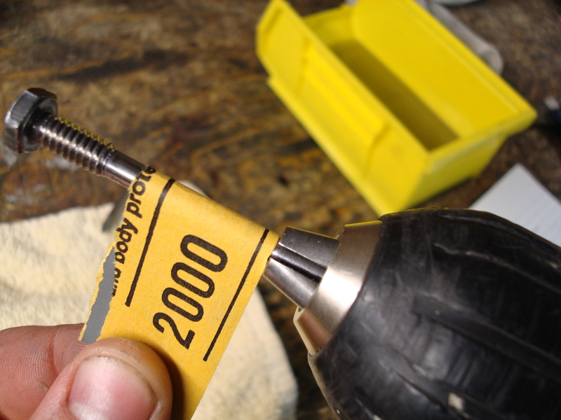
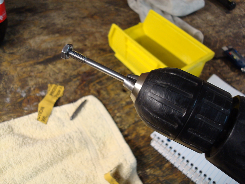
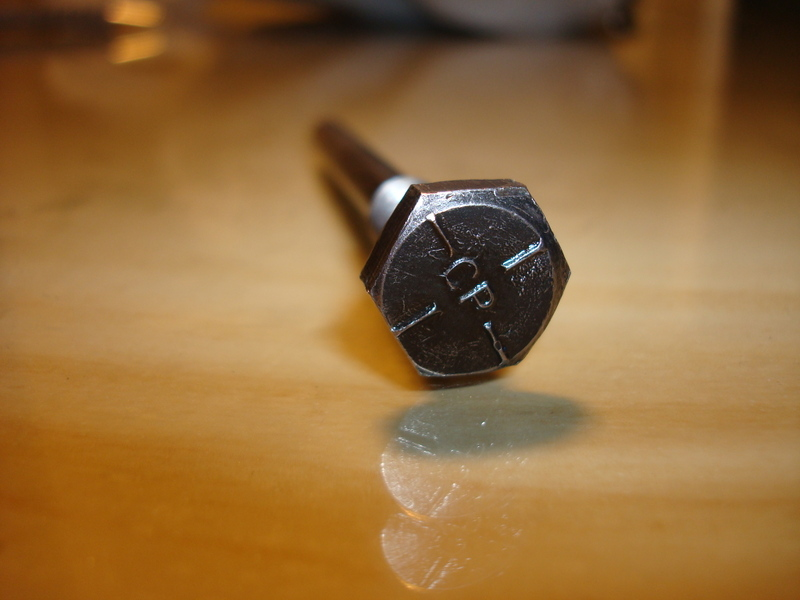
This is what an original GM Posi screw/pin looks like on the head…
By Jeremy Smith
If you want the absolute best job out there, you can do it a few ways. One, you can send your diff to Mike Dyer (tracdogg2) or Gary Ramadei (GTR1999), OR you can build it yourself to their standards – which will probably cost you a little more because you have to buy the correct tools, pay for your mistakes (which will happen, trust me on this one), and build yourself custom tools…but you will have them for the rest of your life (and you can say that you built it!). I suggest you get in contact with them whether you plan on rebuilding your differential yourself or are having them rebuild it for you. I for one will no longer buy diff parts without first contacting Gary or Mike – they are straight up and only sell quality stuff.
I am writing this rebuild paper out of my own will. I do not intend to take any business away from the Corvette vendors out there – I am just a regular guy who likes to build stuff, that’s it. I’m only 18, and don’t even have the abilities to start a differential business. Sure I’ll help guys rebuild their diff and answer questions, but I’m not taking in work to compete with the vendors. I don’t have the time, money or even the facilities for that matter. This paper is designed to assist those who want to take on the task of rebuilding a diff by themselves.
If you have any doubt about your abilities to rebuild a diff, then send it out to get rebuilt by a professional. I am not liable for any of the work you do.
First Inspection/Disassembly of Unit
Once you get the diff removed from the vehicle, the first thing you want to do is go out and by yourself a cheap engine stand (3 wheeled) from Princess Auto (Canada’s form of Harbor Freight). The diff only weighs about a hundred pounds, so any engine stand will do. I can’t imagine anyone rebuilding a diff without this handy tool. It makes life so much easier, and reduces the amount of effort it actually takes to work on the thing; buy yourself one, it’s worth the money. I don’t have that many pictures from the beginning of the rebuild, so I will try to explain this the best I can. The first thing you want to do is mount the diff on the engine stand. Use two bolts in the strut bracket holes to mount it, and then place it on the stand. Unbolt the diff cover and then put an oil container on the floor. Turn the diff upside down and drain out all of the oil – turn the pinion a few times to help some of it pour out. Flip the diff back over and inspect the carrier and housing for any damage. Here are some pics of my damage. The previous owner must have lost a ring gear bolt and it chewed up the side of the housing – I used a die grinder and dremel to clean up the groove marks and make them baby smooth. I was lucky in that the bearing cap pads were in good shape otherwise.
When it came to the gears, I bought new Toms 3.73’s. I would not attempt to reuse gears unless I knew how they sounded before tearing them apart – even then I won’t reuse them. The reason being is because if they sounded like crap before you tore everything apart, they can’t be made any better, as they have already worn into the pinion mesh, and trying to repattern them to get less noise out of them is a waste of time…you’ll never get a consistent pattern. I’ll never reuse gears in my entire life, even if they sounded good, because I don’t think it is worth it. If you plan on reusing your gears, you need to measure everything before you take it apart – shims, backlash, gear pattern…everything. You need to get it in the exact same setup when you reinstall everything, or else the gears will make noise and howl. I am not going to go into much detail here on how to do this, as I don’t have this type of experience (I didn’t reuse my gears, so I didn’t have to worry). I know how to setup new gears, but I don’t want to give you the wrong info if you plan on reusing used gears.
Get yourself a cheap pair of snap ring pliers, and remove the side yokes. They may be ground down and stuck inside the posi case – you might have to use a dremel tool to get the yokes out. It takes some careful grinding, but they should eventually slip out of the housing.
Now, Gary and Mike mention to mark the carrier caps before you remove them. I tore everything apart before marking them and they got mixed up. I had to figure out which cap was for which side. Even if you do mark them before you remove them, you still need to refit them to the housing saddles – bubba may have been in here before and reinstalled the caps on the wrong sides. I refit mine using a special trick I learned from Mike over the phone – this guy is incredible, he knows everything. So does Gary – he also is a genius. It’s too bad they live in different cities, because they would make one hell of a diff shop. These two fellows also check the fit of their caps, even if they did mark them before removing them from the housing. For now, use a sharpie to mark the carrier caps, as they may not be on the correct sides. Gary and Mike are the only people out there that fit their caps – no diff shop will do this. To fit a steel bearing cap, you will need a bridgeport mill and a surface grinder, both of which I don’t own. To fit a stock cap correctly is very easy, and requires basic hand tools and patience. I will go into detail on this later on in the paper, as you need to first clean the housing.
If you want the best differential out there, then you will not be reusing any of the bolts and washers in the differential – you’ll be buying all new grade 8 bolts. They’re cheap, and they are easy to get…replace them. Get yourself a box and some plastic Ziploc bags. As you remove parts, label the bags and then put the bags in the box. This will keep you organized, even if you never touch the parts again. I never did this when I disassembled everything. My dad did most of the disassembly, as this was supposed to be his project (sorry Dad). I ended up taking it over as I am a much bigger perfectionist than he is; I also wanted to learn how to rebuild a diff. After reading all of Mike’s and Gary’s post, and reading threads by people who had their stuff rebuilt by shops or vendors (and then their setups being worse than before they had them rebuilt), I said to myself screw it. I’m doing a frame off restoration; why not suck all this information out of these two guys so I have it for the rest of my life. If I ever had something farmed out, it would be to Mike or Gary, both for their quality of work and because of all the help they have given me.
Okay, so now you have the bearing caps removed and stored away. Next remove the carrier from the housing. Try to keep the side shim packs together so you can use them as a reference point when setting up the diff. If you reuse your gears, this is critical. If you install new gears (like me) then it isn’t that critical as you will need to redo everything anyways. When using new gears, you need to make sure that the carrier is nice and tight in the housing before you preload each of the shim packs – I will go into more detail on this later in the paper, as we are not near this rebuild phase yet. Put the carrier aside for now, we will disassemble and inspect this more later.
Now, if you are reusing your gears, you need to be extra careful that you don’t damage the pinion when removing it from the housing. Removing the pinion nut and then the pinion flange will let the pinion hit the floor (the outer bearing is not a press fit, it is slip fit). So for all you “used gear gurus” out there, now is the time to make your first homemade tool for the rebuild. You will use this tool a ton when you start assembling the diff, so put some work into it. It’s a pinion holder. All it is a piece of metal that has three holes drilled in it - two holes for bolts to go into the bearing pads, and a hole in the middle for a bolt. I tapped the center hole for the bolt, so you can tighten and loosen it to sit on the face of the pinion. You’ll probably not find this long of a bolt threaded this deep. I decided to use a tap and die set to make the threads go almost all the way to the top, not necessary, but I like to overdo things.
For the people out there that plan on using new gears, you don’t have to worry about hurting the used pinion. I for one didn’t care if the pinion hit the ground, because it was going to be used as a paperweight for the rest of its life anyways. So, when you remove the pinion nut and press off the pinion flange, keep your feet clear of its path (you don’t want any broken toes do you?). Here is what I used to pull off the flange, it worked great. It’s a tool from a bearing puller I bought, and two extra long bolts for the pinion flange holes. You will need this tool a lot when you setup the gear pattern, so you’re better off going out and buying one now. I think I saw a cheap small duty gear puller at Auto Value which might fit and work for this application, but you’d have to check to be sure.
If your pinion is still stuck in the housing, do the following. Get your self a dead-blow rubber hammer and hit the pinion end while you hold your hand in the housing to catch the pinion. It should pop out with a little effort. Put the outer bearing in a Ziploc bag and in the box to keep you organized (you won’t be using that again anyways). Now it is time to remove the inner pinion bearing using a hydraulic press. Now, if you have a friend that is willing to let you borrow their hydraulic press for a few months, then do it. But if you just have a friend that says you can come over and use it whenever you want, then you will want to buy yourself a cheap one from Princess Auto (AKA Harbor Freight). The reason being is because it will get extremely old when you have to run over to his house every second day to press something else on…it honestly isn’t worth it. I hate buying tools from Princess Auto because they are always cheap quality and usually break or just don’t get the job done. I just couldn’t pass on this hydraulic press though, it was a steal. I think I paid $130 Canadian for the 12 ton press. If you were to build it yourself, that’s how much the steel would cost you to build the frame, so you are still saving yourself money. The hydraulic bottle will probably go in a couple of years, but you can get new hydraulic bottles from industrial places which are way better in quality, plus they are real easy to replace. I have used this unit to rebuild my trailing arms and steering box – it is great. I even used it to straighten out my steering bar, that saved me $100 alone. I believe Gary uses the exact same press, only he had to replace the hydraulic bottle because it crapped out. Other than that, this is a great tool (the diff is now finished as I write this paper, and the press is still going strong). Here is a pic of it:
To press off the pinion bearing, you’ll need a bearing splitter. I bought one from Princess Auto when I got the press, and did a little mod to it. The pinion bearing is pressed tight on top of the pinion shim, which is underneath the bearing. It is very hard to remove it without damaging the cage. It’s not that critical if you damage the cage on this bearing, as it will be replaced anyways. But when it comes time to the final setup, you might have to press off the good bearing to change the shim size, even if the setup bearings were perfect with a certain shim. What I did was smooth out the inside of the bearing splitter so it fit underneath the bearing sides a little more. You can see what I did in this pic:
Here is a picture from Gary on how to press off the pinion bearing (I didn’t have a pic).
Now it’s time to buy yourself a micrometer or caliper. I bought myself a decent one which is digital, and it’s pretty damn accurate. It’s nothing to be proud of though, its mastercraft brand (from Canadian Tire), which I absolutely hate. The next time I rebuild a diff or trailing arms, I will be buying myself a nice expensive Starrett Caliper and dial indicator/base. I think I paid $50 for my caliper and I always test it against my feeler gauges, which go all the way down to 0.0015. Measure the original pinion shim and take note of it. I think my original shim was 0.026’’.
The next step is to remove the pinion bearing races using a brass drift and hammer. Go slowly as not to gouge the edges of where the race sits (if you do, its not a big deal, as a dremel tool with metal cutting wheel works nicely to chamfer the edge again).
Cleaning/Painting
Now you have everything removed from the housing and it is time to clean it down to the bare metal. I had a bucket with a tightly sealed lid in the garage which fit perfect for the diff housing. I poured some gas, degreaser, soap and water into it and then mixed it all together. It will smell bad, so you need to keep the lid tightly sealed lid on it when it soaks in the garage. Place the housing in the mixture, put the lid on, and then let it sit for about 2-3 days. You’ll be amazed at how well this works. Hose the housing off with some water and soap, and it is down to the metal with minimal effort. The gas turns the oil into nothing…I couldn’t believe how well it worked. Then I taped off all the areas where sand could get into the housing, and sandblasted all the rust off. I built my own blast cabinet, which works great for projects like these.
There are a few ways you can dress up the differential. The easiest and cheapest way is some spray paint from home depot. Lots of people seem to prefer the POR15 stuff, but I never really liked it ( I waited 3 days for a part to dry and it was still wet…after applying thin coats and following all the instructions down to the last letter). I think I may have got a bad batch. I decided to powdercoat my differential. The color is RAL7011:
Paint the rest of your parts at this time as well (side yokes, diff cover, front differential bracket…). If you sandblast your yokes, be careful that you don’t sandblast the area where the seal rides. I accidentally did this and I was not comfortable reusing the yokes (I also wanted to upgrade to the hardened tip ones made by Lonestar.
Posi Case Disassembly
The first thing you want to do is remove the ring gear from the posi case. Take one of your old side yokes and put it in a vise, then place the posi case on top of the side yoke. It works great as a work stand. Use an impact gun to remove the ring gear bolts. The ring gear is a tight fit on the posi case, and you will need to use a hammer with a block of wood to remove it from the carrier. Work your way around the ring gear. If you are reusing you gears, be very careful – the ring gear will eventually pop loose and will fall and hit your vise. I tuned my posi unit without springs, so I wasn’t too concerned with ruining the springs. I cut them out with a dremel tool and cutting wheel. Remove the two plates that the springs were wedged between. Okay, now you are ready to remove the posi pin. PLEASE TAKE NOTE OF THIS!!!!!!!! The pin is not a press fit; it is a slip fit which is held in place with a screw/pin in the carrier. I originally thought it was a press fit, and that I had to press the pin out. So, off I went to my hydraulic press, and pressed out the large posi pin – little did I know that the pin was held in place horizontally with another long pin, and I ruined my posi case. DO NOT PRESS OUT YOUR PIN!!!! First, you need to remove pin #3 in the following diagram…
After you remove this pin, then you can slip the larger pin (#11 in the diagram) out of the housing using your finger. It is a slip fit, not a press fit, so it can be removed with little effort. I had to replace my posi case due to this one mistake – the small pin was crushed when I pressed out the larger pin, and the hole was elongated and broken…a really costly mistake on my part. Once you have removed these two items, you can remove the spider gears. Turn the posi unit by hand until the spider thrust washers drop out from behind the gears and then remove them (you won’t be reusing the thrust washers). Once you remove the spider gears (#10), then the top gear with its respected clutches and retainers will drop down and you can remove them from the carrier. All that is left to do is remove the bottom gear, which the side yoke is sitting on, and set it aside with its clutches and 2 retainers. You will not be reusing the clutches or retainers in the rebuild. However, if your spider gears are in good condition, then you may reuse them. There are two different types of gears – 17 tooth and 18 tooth. The 18 tooth gears are not as strong as the 17 tooth gears. Here is a picture from Gary regarding the difference between them (the good ones, and the ones you want, are on the right side). If you happen to have the 18 tooth gears, I’d replace them now. They are not as strong as the 17 tooth ones.
Degrease and clean the posi case, spider gears, large posi pin, and small pin/screw. Store the clutches and retainers in a zip loc bag. I also forgot to mention that the posi case sometimes has 2-3 shims on each side of the carrier – this was done by your folks at GM to pick up the slack in the case.
Carrier Inspection
You can reuse the carrier as long as it is not damaged and does not have any cracks in it. The large posi pin often elongates the machined holes in the carrier – if it is oblong, you will have to machine it for a larger pin or gears (I think Tom’s differentials does this), or replace the carrier. Look for any cracks and damage. One crack and it is toast unfortunately…don’t risk it, replace it now. All this work you’ll be doing will be for nothing if you have a bad carrier, as it will eventually go and ruin your entire diff.
Polishing the Posi Case
Now you are ready to start tuning your posi unit – it takes a lot of time to do, but it will be worth it in the end. The first thing you want to do is protect the surfaces that you don not want to polish (I used duct tape, as it is much more sticky than masking tape). Tape off the areas where the spider gear thrust washers ride – these areas are very important and you don’t want to ruin or scratch these. You will need a few tools for this job. I used a carbide burr with a dremel tool, die grinder and grinding stones, sandpaper, emery cloth and some roloc disks on a surface prep tool my dad bought me. The basic principle of this job is to remove all the stress areas from the casing – this will prolong the life of your diff, as well as make it much stronger than stock. If you look inside the casing, you’ll notice some “seams” from the casting process. You want to polish these areas as well. When you polish the windows on the carrier, you have to be careful not to continue the polishing past where the clutches ride, but you do want to carry the polishing inside the housing to the areas where the clutches don’t ride. I hope this makes sense. Here is what my new case looked like when I got it in the mail:
Here is the case after polishing (please ignore the carrier bearings, some of these pictures were taken after I decided to redo my work, and they are the best pics I have)…
After the polishing of the posi case is completed, you are ready to move onto the next step.
ARP Ring Gear Bolts
If you plan on using ARP ring gear bolts with your rebuild, now is the time to countersink the holes on you posi case. Gary touched base on this in one of his posts. Basically, what he found was there was a shoulder on the ARP bolts which prevented them from seating flat. The case I bought from Gary already had the holes countersunk, so that saved me from having to do it. A step drill might work to slightly countersink the holes too, but you'd have to ask Gary about that one. This step is mentioned in ARP’s instructions as well.
Beveling the Spider Gears
GM left a lot of slack in the original spring setup – the reason they installed the springs was to take up this slack by putting pressure on the side clutches. The clutches are designed so that they provide resistance when they are turned. By changing the spring rate in the posi unit, all you are doing is reducing side pressure on the clutches, which results in either more posi action or less posi action. They had to install springs because it was not cost effective to tune each unit by hand so there was no slack in the clutches – leaving the springs out would mean that the clutches would not drag across each other and provide no resistance. Thus, instead of the wheel turning at a different rate, it would be extremely sloppy and the spider gear tooth contact would be minimal. When both wheels are turning at the same rate, the 10 tooth spider gears prevent the clutches from turning. One spider gear wants to go left, and one spider gear wants to go right, and they lock up and turn at the same rate like a fixed axle. Thus, there really is no need for posi springs as long as you remove the slack GM left in the setup by shimming the side clutches properly. Too tight, and the clutches act just like the GM setup, and the wear on them will be excessive. Too loose and the spider gear tooth contact will be minimal and weak – and the clutches will not drag across each other providing a smooth motion. This is very time consuming, but it is worth it in the end. GM decided to try and fix their hammering issue by installing snowflake clutches to get more oil between the already stressed side clutches…now all this did was weaken them to the point that they would break.
You are going to be pulling the tolerances in very close, so you want to bevel the four posi gears’ edges. I used a dremel and a grinding stone attachment; just walk the grinding stone across the edges, don't apply any pressure (you want to break the sharp corners).
Parts
You will need to buy yourself a new set of solid clutches, a clutch shim kit, new clutch retainers and new spider thrust washers. The clutch shim kit comes with two sets of 0.010’’-0.045’’ shims in increments of 0.005’’. You will also need to get a hold of some GM posi additive for use when tuning the posi unit. Look over your crosshaft for any wear/tear. The OD of the top and bottom should be 0.747’’, and there should be no signs of the yokes wearing on the shaft. The ID of the holes in the posi case I think are 0.749’’. If it is not up to spec, replace it. Gary sells a shaft that is 0.001’’ oversize, and it is a much tighter fit. That is the one that I used during my rebuild. You also want to check the screw/pin that holds the crosshaft in place. The new pins that GM is making and selling are apparently bad quality compared to the originals - the heads break off real easy if tightened too much, and then you are screwed (no pun intended). I was lucky in getting an original GM one. I think these pins are around 18 bucks, so they aren't cheap. You want to check and see if there is a "step" in the shank of it. If there is, it should be replaced. Go back to that diagram I posted above, and look at item number 2. It is an internal Ľ’’ spring washer. You will need to get a new one (I got a 100 pack from Acklands Grainger). Install it when the posi tuning is completed, as you can only use it once. DO NOT REUSE YOUR OLD ONE! I polished the screw/pin that goes through the cross shaft in the posi case using my drill as a mini lathe…
This is what an original GM Posi screw/pin looks like on the head…

The following 2 users liked this post by stinger12:
Rescue Rogers (01-06-2019),
Vibguy (10-13-2018)
03-30-2008, 07:06 AM
#2
Safety Car
Thread Starter
Posi Tuning
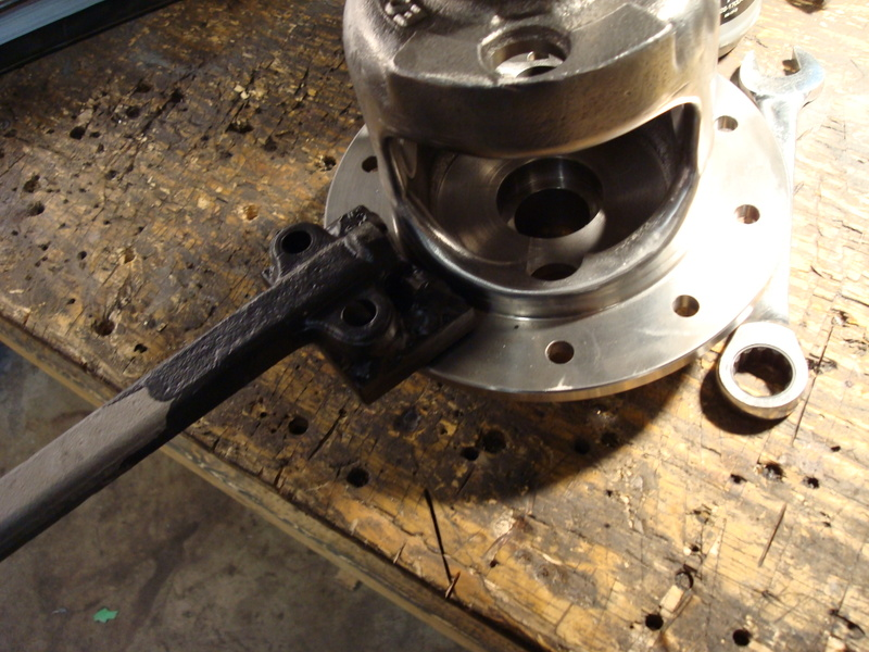
Before you start tuning the posi unit, you need to make yourself another homemade tool. It is a spanner wrench for turning the unit so you can seat the clutches. I took an old lower control arm shaft I had laying around, welded a 1/2'' plate to the end and then welded two bolts to it. The two bolts fit into two of the holes on the posi case, which allows you to turn it with extra leverage. I coated the end of it in some black rubber I had laying around - it prevented me from accidentally scratching my posi case when I was working on it.
After you make your new homemade tool, you are ready to start the posi tuning procedure. I really had to climb into Gary’s head and understand what he was explaining to me as to what he feels when he tunes a posi unit. You wouldn’t believe how many questions I asked him – I’m OCD when it comes to stuff like this.
I clean everything with brake cleaner and compressed air. The next step is to sort out the clutches. They are stamped differently on each side. If you draw you fingernail around the edges, you'll immediately know which side has the deeper stamping. Take a sharpie and put a small "d" on the deeper face so you don't have to keep checking when assembling. The marker will eventually wear off from the oil, but it will keep you organized. I asked Gary as to whether it mattered which way the two clutch packs faced (do all the deep stampings for both sides need to face to the left, or to the right). He said it didn't matter, but you need to keep the deep faces facing in one direction for each clutch pack. Lay all your parts onto a clean rag - once again, this will keep you organized. Oil the clutches with GM posi additive.
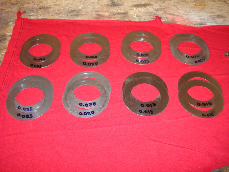
Alright, here is where all the patience on this project comes in - figuring out which size shim is required to set up the posi case. Here is a shot of all the shims that came in Gary's kit...
Refitting Your Bearing Caps
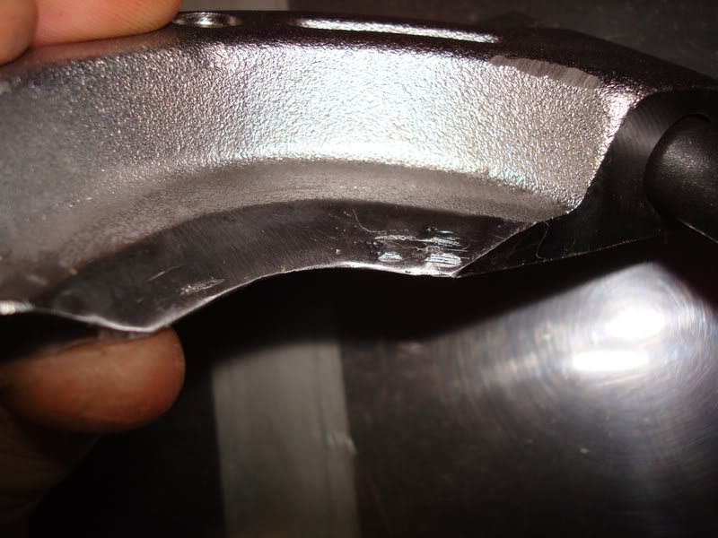
I had an issue with my bearing caps when I remove them – Gary said that there should be 0.001 – 0.002 rock on them. No matter how hard I tried, I couldn’t get them to that spec. What you do is toque the bearing cap’s bolts down after you lightly tap the caps on the races using a small hammer. You do this several times then remove the bolts. The caps are now seated and you can check the rock on them using a feeler gauge. I found that there was a gap of light on top of one of the bearing races – there was no clamping force on the bearing race! No only that, one side had 0.006 rock…I didn’t understand. The other thing I noticed was that no matter how well the caps were seated, you still had light showing through the sides. This got me thinking – how can I accurately measure 0.001 rock when the cap still has yet to form to the bearing race? Here is what one looked like after I seated it.
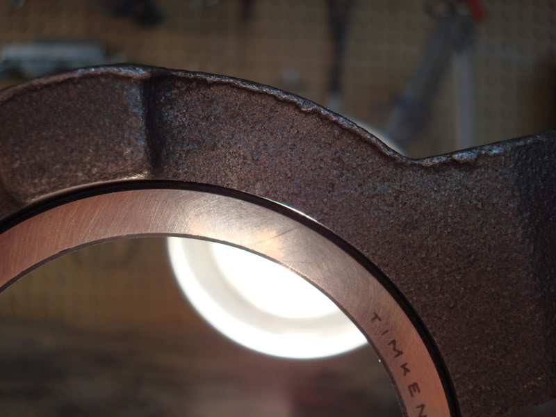
So I gave Mike a call and asked him I could fit my stock caps at home with the limited tools I have. Normally the correct procedure here is to use a bridgeport mill or a cap grinder and open up the bore for 0.001 cap rock. That's what Mike and Gary do. Unfortunately, I am not lucky enough to own one of these high tech machines. He described a technique to me where I can do the cap rock by feel as opposed to using measurement tools. I liked this method because the bearing cap will be formed to the race before you “felt” how the clamping force acts on it. The first thing you want to do is designate one race for the left side of the housing and one race for the right side of the housing. In a perfect world, it wouldn’t matter because the races would all be the same, but its better to be safe than sorry. You will want to keep one race for the left, and one race for the right – don’t mix them up once you fit your bearings caps.
The first thing I did was use the feeler gauge method for finding out with cap fits best on which side (http://www.digitalcorvettes.com/foru...=77377&page=2). I found that the best I could do was get 0.006 rock on the left side, so I had to move the bore up a bit. I used dykem to paint the inside of the cap, then used a flap wheel on a die grinder to slowly work the bore up. This takes lots of time, so be patient. I was able to get it to 0.004 rock, but I still wasn’t satisfied with that light showing through the sides of the cap/race. The cap still hasn’t formed to the race, so 0.004 rock meant nothing to me – once the cap forms after tightening the bolts there can technically be no rock. Then I checked the fit of the cap on the other side. There was a gap above the race, which meant that I had to sand the pads down. First I used layout fluid on the feet of the bearing pad. I took a piece of thick flat glass and used it to slightly sand the pads until I removed all the dykem slowly (I ended up getting 0.003 rock after several attempts with this method – once you remove the dykem, stop and recheck the fit, patience is an asset)– but still, there was light around the edges (no light above the race anymore though) and I still wasn’t satisfied.
I then used the method Mike described to me over the phone. You place the race on the saddle in the housing, leaving about 1/3 of it sticking out of the saddle. Then you lightly tap the cap on the race (make sure it goes on square), and then you torque the bolts to 55 ft/lbs (do each bolt bit by bit as opposed to fully torquing one bolt and then fully torquing the other bolt). Next, take a screwdriver with a plastic handle and try to tap the race into the main part of the saddle. You do this by tapping at the 3:00 o’clock and 9:00 o’clock positions (ONLY THESE POSITIONS) using the plastic handle on the screwdriver. The 12:00 o’clock position is the top of the bearing cap. If you can slowly work the race into the main part of the saddle, then that means that you need to sand a little bit more off the pads (use a flat piece of thick glass and some fine sandpaper – take a little off, then check the fit again). Do this until you can’t work the race into the saddle when the bolts are fully torqued. You can only hit the race so hard with the screwdriver handle because you are working inside of the housing – try whacking it in real hard, working back and forth between the 3:00 o’clock and 9:00 o’clock positions. Once you reach the threshold where you can’t move it into the saddle – stop sanding. This is why it is important to use dykem on the feet of the bearing pads – once the dykem is gone, then you recheck the fit. You want to take off extremely small amounts at a time because you want to reach the threshold where the bearing race actually gets clamped by the bearing cap.
The next thing you want to do is slowly loosen ONE of the bolts. Once loose, take your fingers and tighten the loose bolt the most you can and then use a ratchet/socket to tighten it just a tiny bit more than finger tight. This “forms” the cap to the bearing race. Now, try lightly tapping the race in using the handle of the screwdriver – tap between the 9:00 o’clock and 3:00 o’clock positions. If you are now able to slowly move the race into the saddle, then you are perfect! The point of this last test was to see if there is just enough clamping force to prevent the race from moving – having too much clamping force means that the bearing race will be distorted and the life of your bearings will be decreased.
Do this exact same procedure for your other cap. Let’s go through another scenario. Let’s say you torque the bolts on the right side, and you can’t get the bearing race to go into the saddle using the screwdriver handle. “Perfect” you tell yourself! But then you do the approval test (read the paragraph above) and you can still not move the bearing race into the main part of the saddle by lightly tapping on the 9:00 o’clock and 3:00 o’clock positions. This means that the bore of the bearing cap needs to move up – it is the opposite of sanding the bearing pads, and it requires much more patience to do, but it can be done. I had to do this with one of my caps, so here is how you do it. Go out and buy yourself some layout fluid and layout fluid remover (Dykem is one brand) – it is a metal dye, which machinists use to keep track of their machining on metal parts. It’s almost like coloring metal with a sharpie, but you can’t smudge this stuff off – you need the layout fluid remover for this. You could use a black sharpie if you want as well, but I decided to get myself some layout fluid. By a fine grit flapper wheel and mount it on your die grinder. Sand more towards the top of the bearing pad than to the sides, but still sand the sides. You may have to use a grinding stone to move the bore up a little more and then finish it off with the flapper wheel. The dykem will help you keep track of where else you need to sand. Do this very carefully. If you happen to move the bore up too much, then you can sand the pads a little to get the fit you need. Check the fit of the race often as you want the grinding to be uniform around the top of the race OD, but not as much near the sides of the cap. This is hard to do when you don’t have a Bridgeport/cap grinder, so get it the best you can. TAKE YOUR TIME WITH THIS STEP. Once you finish both caps, then you can stamp them left or right and keep them with their respective races.
I felt more confident in my abilities to correctly fit the caps at home using the method Mike described to me. If you have access to a bridgeport or cap grinder, then you can to the job much better. Mike and Gary have the correct high tech machines for this operation - they both do the same, high quality work.
Installing Pinion Races
Before you install the pinion bearing races, do the following. Take a dremel tool and Chamfer the edge of where the race actually sits – you don’t want any burrs or high spots in this area. Just chamfer the edge to break the sharp corner. Use the edge of a small cutting wheel to do this. After you have removed all the burrs and high spots, you can install the races. Make sure that no metal chips get underneath the races as you are installing them- this is extremely important. If you don’t completely install and seat the bearing races, then your pinion shim size will be affected. I started my races using a bearing race installer, and then I finished it off using my hydraulic press. Don’t max out the press – it will lock up when it hits bottom.
Pinion Prep, Setup Bearings & Pinion Nut
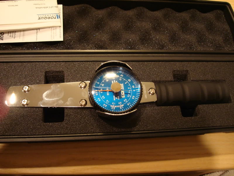
To properly setup the differential, you’ll need to get yourself another tool. You NEED a 0-30 in/lb torque wrench. I bought mine for about $150. Don’t hesitate to buy the correct tool – you need the 0-30 in/lb torque wrench. A regular torque wrench is in ft/lbs, not in/lbs. These devices are extremely accurate and if the pinion bearing preload is not correctly setup, then you’ll ruin the bearings and have to tear the entire diff apart again. You will also need to get yourself 2 extra pinion bearings for the setup – one inner and one outer. Get the exact same brand that you will be installing in the diff. Timken has two different outer pinion bearing part numbers – one has the letter A at the end of it. I’m not too sure why they did this, but they don’t make the one with the letter A at the end of the part number anymore. Don’t mix the two up. I’m not sure if they use the same races, which Is why I am mentioning it here. The outer bearing is already a slip fit and you don’t need to do any work to it to make it into a setup bearing. If you are using a new set of gears, then there will be a black coating on the pinion shaft that prevents the outer bearing from going on. Use some very light sandpaper to clean up the pinion shaft – just take off the black coating, no more. The large inner bearing is a press fit, so you’ll need to take your die grinding stone and open up the ID a bit to make it a slip fit. The reason you are making this bearing slip fit is because the pinion shim is located underneath the bearing. Once you are done setting up the diff, then you will need to press on the real bearing.
The pinion flange will be a very tight fit on the pinion splines if you’re using new gears. Use some lapping compound on the splines to remove and install the flange several times, until it is a better fit on the splines. Don’t make it loose, just make it so it isn’t extremely tight.
Okay, this is extremely important, so pay close attention. Clean your setup bearings with brake cleaner. The oils left from the factory will mess with your torque wrench readings, trust me on this one. After you thoroughly clean the setup bearings, oil them lightly with 90 weight gear oil and work it into the bearing rollers.
You will also need to make yourself a real beefy pinion flange holder so you don’t over-tighten the setup bearings. I was using an impact gun at first to get the preload on my setup bearings – not a good idea. I eventually had to replace them because once you over tighten them, it will mess with your torque readings. I don’t know why it does this, but it just does. Gary says that every 4-5 jobs he replaces the setup bearings with new ones because they mess with the readings on the torque wrench as well. You’ll be hand tightening the nut during setup. Use a long piece of pipe and weld a metal plate on the end of it so it mounts to the pinion flange. Make it just like the spanner wrench you used when setting up your posi unit – you want to be able to take it on and off in a snap so you can see how much more you need to torque the nut to get the proper preload. This is particularly important when you are doing the final setup using the crush sleeve. You don’t want to have to unbolt the plate, then measure the preload, then bolt the plate back on the flange, then repeat. You want to be able to just pull it off the flange and reinstall it just that easily. Make it real strong; you wouldn’t believe how much force is required to crush one of those sleeves. I broke my flange holder during setup and I had loctite on the pinion nut at the time (I had to pull the entire assembly apart to redo my work again). I had to rush to fix it before the thread locker setup. Try and make something that uses all 4 bolt holes as opposed to just two…it will be much stronger that way.
You will also need to cut the locking portion off of your old pinion nut – this will allow you to use it like a normal nut. This is for when you setup the bearings – you won’t be using this nut when you install the crush sleeve and real bearings.
How to Measure Bearing Preload
To measure preload, you put the torque wrench on the nut and set it to zero. You rotate the tool 360 degrees several times until you get up to a nice rotating speed and read what the needle says. Don’t worry about what the needle says when you start and when you stop – what is important is everything in between. The reading should be within 2-3 in/lbs of each other (like 15 to 18 for instance…it’s not just going to stay in one spot, that’s how sensitive this tool is). If they aren’t within that 2-3 in/lb range then either you didn’t clean the bearings well enough (remember what I said about the factory oils messing with your bearing preload?), or you may have over tightened the pinion nut and ruined the setup bearings. I fell in both categories on this one and it really stumped me. Cleanliness is next to godliness. If you happened to over tighten the setup bearings to much you might have to buy a new set and start over.
Before you start tuning the posi unit, you need to make yourself another homemade tool. It is a spanner wrench for turning the unit so you can seat the clutches. I took an old lower control arm shaft I had laying around, welded a 1/2'' plate to the end and then welded two bolts to it. The two bolts fit into two of the holes on the posi case, which allows you to turn it with extra leverage. I coated the end of it in some black rubber I had laying around - it prevented me from accidentally scratching my posi case when I was working on it.
After you make your new homemade tool, you are ready to start the posi tuning procedure. I really had to climb into Gary’s head and understand what he was explaining to me as to what he feels when he tunes a posi unit. You wouldn’t believe how many questions I asked him – I’m OCD when it comes to stuff like this.
I clean everything with brake cleaner and compressed air. The next step is to sort out the clutches. They are stamped differently on each side. If you draw you fingernail around the edges, you'll immediately know which side has the deeper stamping. Take a sharpie and put a small "d" on the deeper face so you don't have to keep checking when assembling. The marker will eventually wear off from the oil, but it will keep you organized. I asked Gary as to whether it mattered which way the two clutch packs faced (do all the deep stampings for both sides need to face to the left, or to the right). He said it didn't matter, but you need to keep the deep faces facing in one direction for each clutch pack. Lay all your parts onto a clean rag - once again, this will keep you organized. Oil the clutches with GM posi additive.
Alright, here is where all the patience on this project comes in - figuring out which size shim is required to set up the posi case. Here is a shot of all the shims that came in Gary's kit...
Refitting Your Bearing Caps
I had an issue with my bearing caps when I remove them – Gary said that there should be 0.001 – 0.002 rock on them. No matter how hard I tried, I couldn’t get them to that spec. What you do is toque the bearing cap’s bolts down after you lightly tap the caps on the races using a small hammer. You do this several times then remove the bolts. The caps are now seated and you can check the rock on them using a feeler gauge. I found that there was a gap of light on top of one of the bearing races – there was no clamping force on the bearing race! No only that, one side had 0.006 rock…I didn’t understand. The other thing I noticed was that no matter how well the caps were seated, you still had light showing through the sides. This got me thinking – how can I accurately measure 0.001 rock when the cap still has yet to form to the bearing race? Here is what one looked like after I seated it.
So I gave Mike a call and asked him I could fit my stock caps at home with the limited tools I have. Normally the correct procedure here is to use a bridgeport mill or a cap grinder and open up the bore for 0.001 cap rock. That's what Mike and Gary do. Unfortunately, I am not lucky enough to own one of these high tech machines. He described a technique to me where I can do the cap rock by feel as opposed to using measurement tools. I liked this method because the bearing cap will be formed to the race before you “felt” how the clamping force acts on it. The first thing you want to do is designate one race for the left side of the housing and one race for the right side of the housing. In a perfect world, it wouldn’t matter because the races would all be the same, but its better to be safe than sorry. You will want to keep one race for the left, and one race for the right – don’t mix them up once you fit your bearings caps.
The first thing I did was use the feeler gauge method for finding out with cap fits best on which side (http://www.digitalcorvettes.com/foru...=77377&page=2). I found that the best I could do was get 0.006 rock on the left side, so I had to move the bore up a bit. I used dykem to paint the inside of the cap, then used a flap wheel on a die grinder to slowly work the bore up. This takes lots of time, so be patient. I was able to get it to 0.004 rock, but I still wasn’t satisfied with that light showing through the sides of the cap/race. The cap still hasn’t formed to the race, so 0.004 rock meant nothing to me – once the cap forms after tightening the bolts there can technically be no rock. Then I checked the fit of the cap on the other side. There was a gap above the race, which meant that I had to sand the pads down. First I used layout fluid on the feet of the bearing pad. I took a piece of thick flat glass and used it to slightly sand the pads until I removed all the dykem slowly (I ended up getting 0.003 rock after several attempts with this method – once you remove the dykem, stop and recheck the fit, patience is an asset)– but still, there was light around the edges (no light above the race anymore though) and I still wasn’t satisfied.
I then used the method Mike described to me over the phone. You place the race on the saddle in the housing, leaving about 1/3 of it sticking out of the saddle. Then you lightly tap the cap on the race (make sure it goes on square), and then you torque the bolts to 55 ft/lbs (do each bolt bit by bit as opposed to fully torquing one bolt and then fully torquing the other bolt). Next, take a screwdriver with a plastic handle and try to tap the race into the main part of the saddle. You do this by tapping at the 3:00 o’clock and 9:00 o’clock positions (ONLY THESE POSITIONS) using the plastic handle on the screwdriver. The 12:00 o’clock position is the top of the bearing cap. If you can slowly work the race into the main part of the saddle, then that means that you need to sand a little bit more off the pads (use a flat piece of thick glass and some fine sandpaper – take a little off, then check the fit again). Do this until you can’t work the race into the saddle when the bolts are fully torqued. You can only hit the race so hard with the screwdriver handle because you are working inside of the housing – try whacking it in real hard, working back and forth between the 3:00 o’clock and 9:00 o’clock positions. Once you reach the threshold where you can’t move it into the saddle – stop sanding. This is why it is important to use dykem on the feet of the bearing pads – once the dykem is gone, then you recheck the fit. You want to take off extremely small amounts at a time because you want to reach the threshold where the bearing race actually gets clamped by the bearing cap.
The next thing you want to do is slowly loosen ONE of the bolts. Once loose, take your fingers and tighten the loose bolt the most you can and then use a ratchet/socket to tighten it just a tiny bit more than finger tight. This “forms” the cap to the bearing race. Now, try lightly tapping the race in using the handle of the screwdriver – tap between the 9:00 o’clock and 3:00 o’clock positions. If you are now able to slowly move the race into the saddle, then you are perfect! The point of this last test was to see if there is just enough clamping force to prevent the race from moving – having too much clamping force means that the bearing race will be distorted and the life of your bearings will be decreased.
Do this exact same procedure for your other cap. Let’s go through another scenario. Let’s say you torque the bolts on the right side, and you can’t get the bearing race to go into the saddle using the screwdriver handle. “Perfect” you tell yourself! But then you do the approval test (read the paragraph above) and you can still not move the bearing race into the main part of the saddle by lightly tapping on the 9:00 o’clock and 3:00 o’clock positions. This means that the bore of the bearing cap needs to move up – it is the opposite of sanding the bearing pads, and it requires much more patience to do, but it can be done. I had to do this with one of my caps, so here is how you do it. Go out and buy yourself some layout fluid and layout fluid remover (Dykem is one brand) – it is a metal dye, which machinists use to keep track of their machining on metal parts. It’s almost like coloring metal with a sharpie, but you can’t smudge this stuff off – you need the layout fluid remover for this. You could use a black sharpie if you want as well, but I decided to get myself some layout fluid. By a fine grit flapper wheel and mount it on your die grinder. Sand more towards the top of the bearing pad than to the sides, but still sand the sides. You may have to use a grinding stone to move the bore up a little more and then finish it off with the flapper wheel. The dykem will help you keep track of where else you need to sand. Do this very carefully. If you happen to move the bore up too much, then you can sand the pads a little to get the fit you need. Check the fit of the race often as you want the grinding to be uniform around the top of the race OD, but not as much near the sides of the cap. This is hard to do when you don’t have a Bridgeport/cap grinder, so get it the best you can. TAKE YOUR TIME WITH THIS STEP. Once you finish both caps, then you can stamp them left or right and keep them with their respective races.
I felt more confident in my abilities to correctly fit the caps at home using the method Mike described to me. If you have access to a bridgeport or cap grinder, then you can to the job much better. Mike and Gary have the correct high tech machines for this operation - they both do the same, high quality work.
Installing Pinion Races
Before you install the pinion bearing races, do the following. Take a dremel tool and Chamfer the edge of where the race actually sits – you don’t want any burrs or high spots in this area. Just chamfer the edge to break the sharp corner. Use the edge of a small cutting wheel to do this. After you have removed all the burrs and high spots, you can install the races. Make sure that no metal chips get underneath the races as you are installing them- this is extremely important. If you don’t completely install and seat the bearing races, then your pinion shim size will be affected. I started my races using a bearing race installer, and then I finished it off using my hydraulic press. Don’t max out the press – it will lock up when it hits bottom.
Pinion Prep, Setup Bearings & Pinion Nut
To properly setup the differential, you’ll need to get yourself another tool. You NEED a 0-30 in/lb torque wrench. I bought mine for about $150. Don’t hesitate to buy the correct tool – you need the 0-30 in/lb torque wrench. A regular torque wrench is in ft/lbs, not in/lbs. These devices are extremely accurate and if the pinion bearing preload is not correctly setup, then you’ll ruin the bearings and have to tear the entire diff apart again. You will also need to get yourself 2 extra pinion bearings for the setup – one inner and one outer. Get the exact same brand that you will be installing in the diff. Timken has two different outer pinion bearing part numbers – one has the letter A at the end of it. I’m not too sure why they did this, but they don’t make the one with the letter A at the end of the part number anymore. Don’t mix the two up. I’m not sure if they use the same races, which Is why I am mentioning it here. The outer bearing is already a slip fit and you don’t need to do any work to it to make it into a setup bearing. If you are using a new set of gears, then there will be a black coating on the pinion shaft that prevents the outer bearing from going on. Use some very light sandpaper to clean up the pinion shaft – just take off the black coating, no more. The large inner bearing is a press fit, so you’ll need to take your die grinding stone and open up the ID a bit to make it a slip fit. The reason you are making this bearing slip fit is because the pinion shim is located underneath the bearing. Once you are done setting up the diff, then you will need to press on the real bearing.
The pinion flange will be a very tight fit on the pinion splines if you’re using new gears. Use some lapping compound on the splines to remove and install the flange several times, until it is a better fit on the splines. Don’t make it loose, just make it so it isn’t extremely tight.
Okay, this is extremely important, so pay close attention. Clean your setup bearings with brake cleaner. The oils left from the factory will mess with your torque wrench readings, trust me on this one. After you thoroughly clean the setup bearings, oil them lightly with 90 weight gear oil and work it into the bearing rollers.
You will also need to make yourself a real beefy pinion flange holder so you don’t over-tighten the setup bearings. I was using an impact gun at first to get the preload on my setup bearings – not a good idea. I eventually had to replace them because once you over tighten them, it will mess with your torque readings. I don’t know why it does this, but it just does. Gary says that every 4-5 jobs he replaces the setup bearings with new ones because they mess with the readings on the torque wrench as well. You’ll be hand tightening the nut during setup. Use a long piece of pipe and weld a metal plate on the end of it so it mounts to the pinion flange. Make it just like the spanner wrench you used when setting up your posi unit – you want to be able to take it on and off in a snap so you can see how much more you need to torque the nut to get the proper preload. This is particularly important when you are doing the final setup using the crush sleeve. You don’t want to have to unbolt the plate, then measure the preload, then bolt the plate back on the flange, then repeat. You want to be able to just pull it off the flange and reinstall it just that easily. Make it real strong; you wouldn’t believe how much force is required to crush one of those sleeves. I broke my flange holder during setup and I had loctite on the pinion nut at the time (I had to pull the entire assembly apart to redo my work again). I had to rush to fix it before the thread locker setup. Try and make something that uses all 4 bolt holes as opposed to just two…it will be much stronger that way.
You will also need to cut the locking portion off of your old pinion nut – this will allow you to use it like a normal nut. This is for when you setup the bearings – you won’t be using this nut when you install the crush sleeve and real bearings.
How to Measure Bearing Preload
To measure preload, you put the torque wrench on the nut and set it to zero. You rotate the tool 360 degrees several times until you get up to a nice rotating speed and read what the needle says. Don’t worry about what the needle says when you start and when you stop – what is important is everything in between. The reading should be within 2-3 in/lbs of each other (like 15 to 18 for instance…it’s not just going to stay in one spot, that’s how sensitive this tool is). If they aren’t within that 2-3 in/lb range then either you didn’t clean the bearings well enough (remember what I said about the factory oils messing with your bearing preload?), or you may have over tightened the pinion nut and ruined the setup bearings. I fell in both categories on this one and it really stumped me. Cleanliness is next to godliness. If you happened to over tighten the setup bearings to much you might have to buy a new set and start over.
Last edited by stinger12; 05-05-2008 at 10:59 PM.
03-30-2008, 07:08 AM
#3
Safety Car
Thread Starter
This is important, so take note of it. You want to select which parts you will be using on the ring gear side of the casing, and which parts you will be using on the other side of the casing. Keep them separated. Technically, it shouldn’t matter which side they are on because they should all be the same, but do it. For instance, 0.001’’ in one clutches’ thickness will make a difference in your setup. The tolerances on this setup are important. Also decide which 10 tooth spider gear will be on the left side of the casing and right side of the casing when looking at it from the front. KEEP THEM SEPARATED! This includes everything – separate the thrust washers, the spider gears, the large gears, the retainers…everything. I may be a little **** when it comes to these things, but it is easier to eliminate this source of error when setting up the unit (like maybe I’ve been swapping the parts for each side and that’s why I keep getting different results).
Start off with a 0.040 shim on each side. First, oil one shim with posi additive and place it on the bottom (ignore the shim size in this picture, this was during final assembly)…
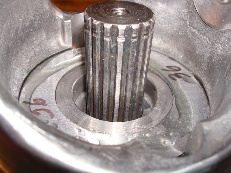
Next, take the shim pack that you have designated for the side which you are working on (use GM posi additive to oil each clutch really well) and place it in the bottom of the carrier without its retainers. Oil the retainers with GM additive. Poke your finger through the hole in the bottom of the case and insert one of the retainers and then drop it down. Turn the case around and do the same on the other side.
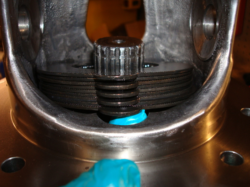
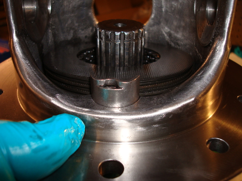
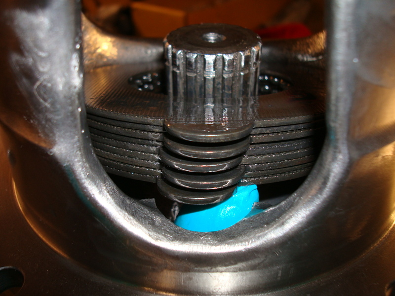
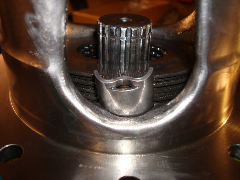
Next, take the large gear which you have designated for this side of the posi case and place it on top of the yoke. Turn the posi unit until the clutches line up with the gear and then fully seats. Make sure the top clutch is well oiled. Now you are ready to install the other side’s parts, but this time you’ll be doing it a bit differently. Oil the clutches using GM additive. Then take your clutches and place them on the large 17 tooth gear. Take your 0.040 shim, oil it on both sides and place it on top of the clutch pack. Take this assembly and place it in the posi case.After you do this, take your 2 retainers, oil them, and place them on the clutch pack.
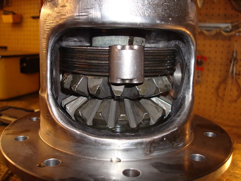
Pull the assembly up into the top of the case and support it with a screwdriver until you are ready to install the 10 tooth spiders and thrust washers.
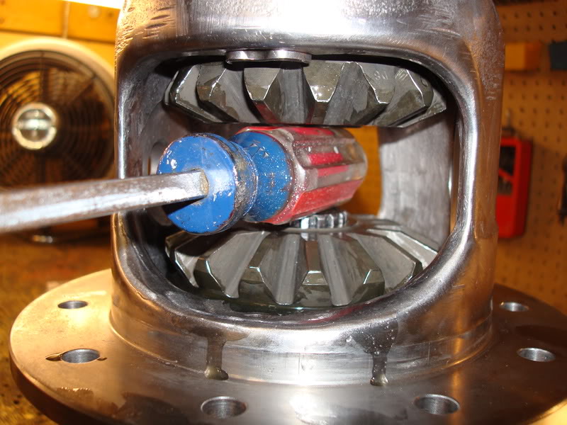
Next, take one spider gear, place it in the case, and rotate the entire unit until it is at the back window. Insert your crossshaft temporarily, then insert your other spider gear, then remove the crosshaft and turn the unit so the spider gears end up on there respective sides (you did this before when you separated the parts between the sides, remember?). Take thee left thrust washer that you labeled and oil it well, then push it behind the spider gear. It will probably be a very tight fit, but it will eventually squeeze in there.
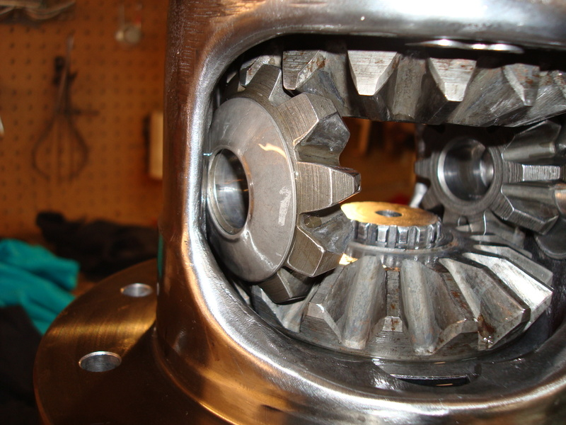
Use a small punch to align the thrust washer and repeat for the other side. Insert the crosshaft and the screw/pin that you polished and you are ready for your first test.
Once you install all the gears and shims in the casing, you want to seat the clutches on each side. Do this by rotating the posi case about 50 times per side using the spanner wrench you made. When it comes to setting up the posi case - patience is a virtue. You need to get inside Gary's head and feel what he's feeling; it took me a really long time to understand what he was trying to explain to me. Lets say the 0.040 shims are too tight. The next thing you want to do is take those shims out and replace them with 0.035 shims. Seat the clutches again using your homemade spanner wrench. Next, take your bare hands and try rotating the posi case. Try it on one side, then flip it over and try it on the other side. If you are not able to turn the posi case by hand smoothly, then you need to try some 0.030 shims. Do exactly the same thing - seat the clutches again try rotating each side using your bare hands. You want the feel to be smooth - you will feel a slight spider gear bumpiness. If you don't feel a slight bumpiness, then that means the gears are now too loose. Basically, what this tells you is that the shims sizes you need are between 0.030 and 0.035. You need to figure out which shim for both sides is needed. They may be different sizes - it depends on the posi case.
So now you have figured out which size shims are too tight and which size shims are too loose. You will be using your spanner wrench tool to seat the clutches, but you will be using your hands to tune to tune the posi unit for feel. The next step is figuring out which size shim is needed on each side of the posi case. When I rebuilt my case, I found that a 0.035 shim on both sides felt a bit different (the side which is on the yokes is the one you are basically testing for tightness). With the ring gear side on the yoke, I turned it with my hands and found it to be a little too loose; but when I flipped the casing over and tested the other side, I found it was a little bit tighter but still smooth (but they were both 0.035 shims...so what gives?). This meant that the machining of the casing was a bit different on each side. Thus, the shim sizes were going to be different. I had Gary grind me up 2 sets of shims: 0.036, 0.037, 0.038, and 0.039. The shim I had in there was a 0.035 shim and that was good, so I swapped that one out for a 0.036 shim to see if It was still going to be smooth. I already figured out that the side opposite the ring gear was too loose with the 0.035 shim, so I decided to try a 0.037 shim on that side. The ring gear side was now too tight, but the side opposite the ring gear was also a little too tight. I swapped the ring gear side out for the 0.035 shim again, but left the 0.037 shim in on the other side (one side affects the other side). I was happy with the feel of both sides and left it at that.
Once you are done setting up the posi unit, you can install the screw/pin with its internal lockwasher for the final time. Clean it extremely well with brake cleaner and a q-tip. Clean out the holes extremely well too with brake cleaner. Put the internal lockwasher on the screw/pin and use some 272 high heat loctite on the threads of the screw and hand tighten. You are now ready to install the ring gear.
Ring Gear Installation
The first step to installing the ring gear is to stone the back surface. Use a small file and some sandpaper on something extremely flat to remove all burrs and high spots. Mask off the posi case windows and use some emery cloth to remove all burrs from the flange surface where the ring gear sits against. You don’t want to contaminate your spider gears and internals. Next, use a million q-tips with brake cleaner to clean absolutely every hole in the posi case – no oils should remain. This is extremely important. After all this time and money you have put into the rebuild, the last thing you want to do is lose a ring gear bolt and chew up ever internal piece of the diff…it just isn’t worth it. Even clean the areas where the heads of the bolts sit. Use a tone of brake cleaner in the ring gear holes and even the ring gear bolts (even if they are new). I can’t stress this enough – you have to see was my diff looked like when I cracked it open. The entire posi case was chewed up and metal had been impregnated in the bearing races as well. After you have cleaned absolutely every area, take your 10 old ring gear bolts and cut the heads off of 5 of them. Next, clean all ten bolts with brake cleaner – you don’t want any oils in the ring gear holes (did I mention I was Corvette OCD lol). Screw the 5 bolts without heads into every second hole in the ring gear.
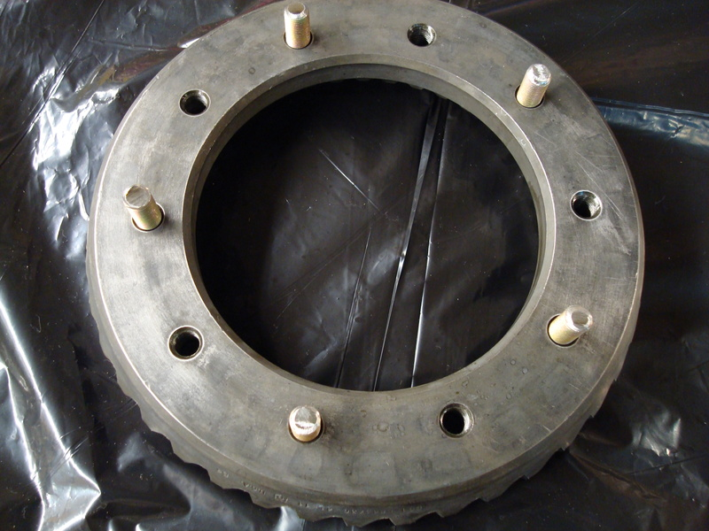
Put the ring gear on the posi unit – the 5 headless bolts you put in every second hole will guide the ring gear onto the flange while you use an impact gun to draw up the ring gear using the other 5 bolts (clean and use the 5 old lockwashers under the heads so the bolts don’t bottom out in the tapped ring gear holes. Make sure that you tighten the bolts so the gear is perfectly seated on the flange. This is important. Remove all the headless, and the headed bolts and you are ready to install the real bolts.
If you are using ARP ring gar bolts, then you don’t use the lockwashers. If you are using grade 8 bolts, THEN YOU NEED THE LOCKWASHERS! Clean the threads of your new bolts with brake cleaner real good, then set them aside. Now you are ready to make yourself another homemade tool. You won’t be able to torque the ring gear bolts properly unless you make this tool. Take some scrap metal and drill two holes in it so it can be mounted to your other old yoke. Then drill 2 holes in the middle so your homemade spanner wrench’s bolts fit into it. You hold this tool while you torque the bolts with your other hand – it prevents the carrier from turning when you torque the bolts.
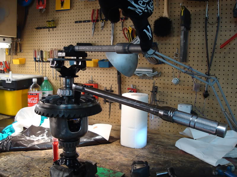
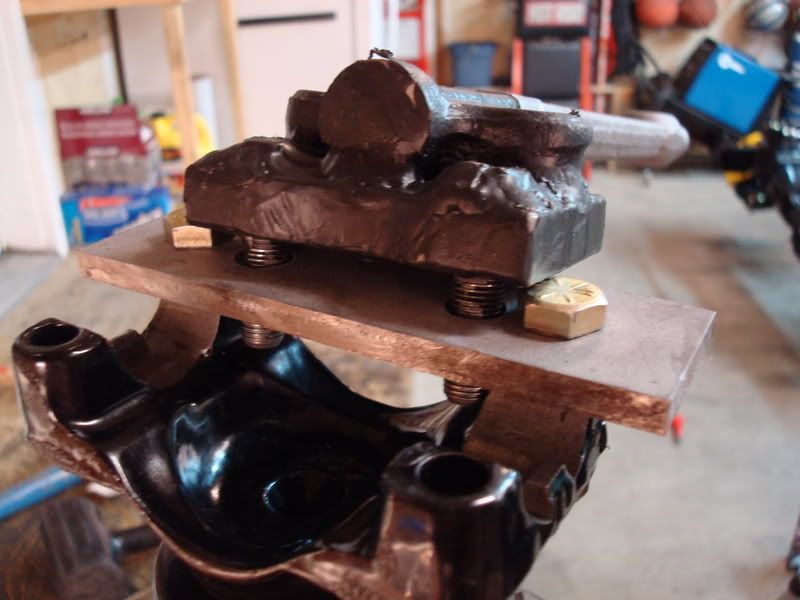
When you torque the ring gear bolts, you need to torque in a star pattern to even the load. It’s easy to lose track of which ones you need to torque next – use a sharpie and mark each hole from numbers one through ten in a star pattern (IGNORE THE CARRIER BEARINGS, THIS WAS AFTER I DECIDED TO REDO MY WORK).
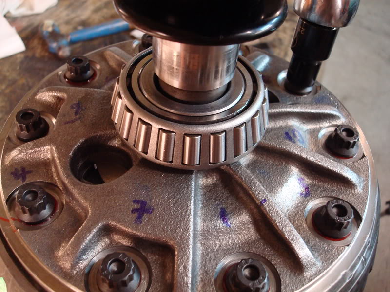
Next, cover the threads of each bolt with loctite 272. It dries without the presence of air (anaerobic thread locker), so you don’t have to worry about it drying until they are tightened. I tried the loctite primer and hated it – the thread locker dried so fast that I wasn’t able to properly torque the bolts before they got locked in the holes (maybe I used too much?). Either way, torque each bolt one at a time. I torqued my ARP bolts to 60 ft/lbs. If you are just using grade 8 bolts, then torque them to 55 ft/lbs. The ARP instructions said to torque them to 45 ft/lbs using their lube or 60 ft/lbs using 30-weight oil. Yeah right, like I wasn’t going to use loctite on the bolts – I called them up and asked them if my spec was okay and they said I was good. Use the loctite – you don’t want these bolts coming out. Let the carrier sit overnight before you do any more work on it.
Installing the Carrier Bearings
To install the carrier bearings, you will need a hydraulic press. I also made myself another tool for this job. Instead of searching for a piece of pipe suitable to press on the bearings, do the following. Take the two old carrier bearings that you removed and cut off the cages and remove all of the rollers. Then use a grinding stone on a die grinder to open up the ID so they don’t get pressed on with the bearings you will be installing. I started to press on the bearings using a bearing race installer. Once the bearings were flush with the top of the carrier, I used my homemade tool to press on the bearing the rest of the way. Make sure you fully press on the bearings, but do not max out the press. It will lock up when you hit bottom. Use brake cleaner to clean out the bearings real good, then use 90 weight gear to oil them. This isn’t that much of an issue for the carrier bearings, but it is absolutely necessary for the pinion bearings. The torque wrench is extremely sensitive and the rust protectant the bearing manufacturer puts on the rollers will mess with your readings – trust me on this one, I will go into more depth on this issue when you setup the bearing preload. I had a hell of a time trying get consistent preload from the torque wrench – Mike Dyer helped me solve that issue. One other thing, don’t press on the bearing cages or you’ll ruin them. Please note that I myself installed the bearings once the carrier was completed and the ring gear was installed, but then I decided to redo all of my work because I was worried the posi unit was too loose and that I could use larger shims in the tuning. Install your bearings after everything is done.
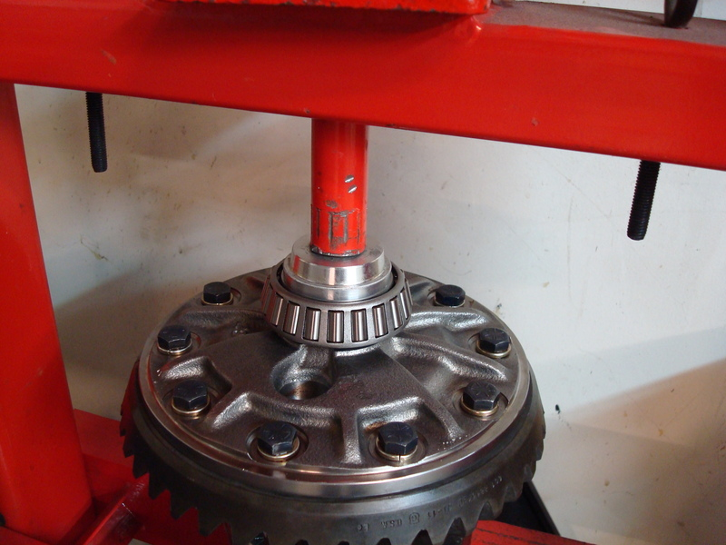
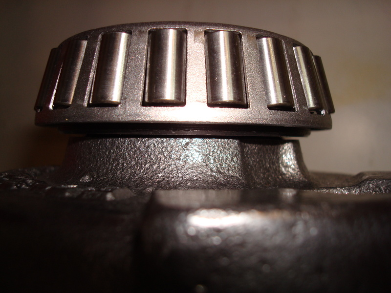
Once flush with the top of the carrier, use your bearing tool you honed with the die grinder to press the bearing on the rest of the way.
My homemade “tool”:
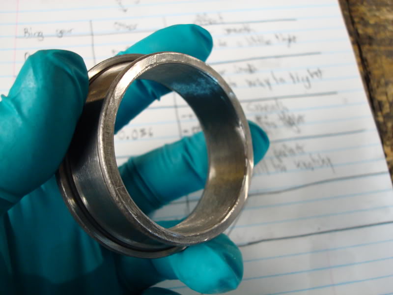
Once one side is completed, flip the case over and support the new installed bearing using the other old carrier bearing you modified. You do not want to press on the cages of the new bearings or you will ruin them.
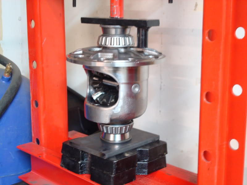
Start off with a 0.040 shim on each side. First, oil one shim with posi additive and place it on the bottom (ignore the shim size in this picture, this was during final assembly)…
Next, take the shim pack that you have designated for the side which you are working on (use GM posi additive to oil each clutch really well) and place it in the bottom of the carrier without its retainers. Oil the retainers with GM additive. Poke your finger through the hole in the bottom of the case and insert one of the retainers and then drop it down. Turn the case around and do the same on the other side.
Next, take the large gear which you have designated for this side of the posi case and place it on top of the yoke. Turn the posi unit until the clutches line up with the gear and then fully seats. Make sure the top clutch is well oiled. Now you are ready to install the other side’s parts, but this time you’ll be doing it a bit differently. Oil the clutches using GM additive. Then take your clutches and place them on the large 17 tooth gear. Take your 0.040 shim, oil it on both sides and place it on top of the clutch pack. Take this assembly and place it in the posi case.After you do this, take your 2 retainers, oil them, and place them on the clutch pack.
Pull the assembly up into the top of the case and support it with a screwdriver until you are ready to install the 10 tooth spiders and thrust washers.
Next, take one spider gear, place it in the case, and rotate the entire unit until it is at the back window. Insert your crossshaft temporarily, then insert your other spider gear, then remove the crosshaft and turn the unit so the spider gears end up on there respective sides (you did this before when you separated the parts between the sides, remember?). Take thee left thrust washer that you labeled and oil it well, then push it behind the spider gear. It will probably be a very tight fit, but it will eventually squeeze in there.
Use a small punch to align the thrust washer and repeat for the other side. Insert the crosshaft and the screw/pin that you polished and you are ready for your first test.
Once you install all the gears and shims in the casing, you want to seat the clutches on each side. Do this by rotating the posi case about 50 times per side using the spanner wrench you made. When it comes to setting up the posi case - patience is a virtue. You need to get inside Gary's head and feel what he's feeling; it took me a really long time to understand what he was trying to explain to me. Lets say the 0.040 shims are too tight. The next thing you want to do is take those shims out and replace them with 0.035 shims. Seat the clutches again using your homemade spanner wrench. Next, take your bare hands and try rotating the posi case. Try it on one side, then flip it over and try it on the other side. If you are not able to turn the posi case by hand smoothly, then you need to try some 0.030 shims. Do exactly the same thing - seat the clutches again try rotating each side using your bare hands. You want the feel to be smooth - you will feel a slight spider gear bumpiness. If you don't feel a slight bumpiness, then that means the gears are now too loose. Basically, what this tells you is that the shims sizes you need are between 0.030 and 0.035. You need to figure out which shim for both sides is needed. They may be different sizes - it depends on the posi case.
So now you have figured out which size shims are too tight and which size shims are too loose. You will be using your spanner wrench tool to seat the clutches, but you will be using your hands to tune to tune the posi unit for feel. The next step is figuring out which size shim is needed on each side of the posi case. When I rebuilt my case, I found that a 0.035 shim on both sides felt a bit different (the side which is on the yokes is the one you are basically testing for tightness). With the ring gear side on the yoke, I turned it with my hands and found it to be a little too loose; but when I flipped the casing over and tested the other side, I found it was a little bit tighter but still smooth (but they were both 0.035 shims...so what gives?). This meant that the machining of the casing was a bit different on each side. Thus, the shim sizes were going to be different. I had Gary grind me up 2 sets of shims: 0.036, 0.037, 0.038, and 0.039. The shim I had in there was a 0.035 shim and that was good, so I swapped that one out for a 0.036 shim to see if It was still going to be smooth. I already figured out that the side opposite the ring gear was too loose with the 0.035 shim, so I decided to try a 0.037 shim on that side. The ring gear side was now too tight, but the side opposite the ring gear was also a little too tight. I swapped the ring gear side out for the 0.035 shim again, but left the 0.037 shim in on the other side (one side affects the other side). I was happy with the feel of both sides and left it at that.
Once you are done setting up the posi unit, you can install the screw/pin with its internal lockwasher for the final time. Clean it extremely well with brake cleaner and a q-tip. Clean out the holes extremely well too with brake cleaner. Put the internal lockwasher on the screw/pin and use some 272 high heat loctite on the threads of the screw and hand tighten. You are now ready to install the ring gear.
Ring Gear Installation
The first step to installing the ring gear is to stone the back surface. Use a small file and some sandpaper on something extremely flat to remove all burrs and high spots. Mask off the posi case windows and use some emery cloth to remove all burrs from the flange surface where the ring gear sits against. You don’t want to contaminate your spider gears and internals. Next, use a million q-tips with brake cleaner to clean absolutely every hole in the posi case – no oils should remain. This is extremely important. After all this time and money you have put into the rebuild, the last thing you want to do is lose a ring gear bolt and chew up ever internal piece of the diff…it just isn’t worth it. Even clean the areas where the heads of the bolts sit. Use a tone of brake cleaner in the ring gear holes and even the ring gear bolts (even if they are new). I can’t stress this enough – you have to see was my diff looked like when I cracked it open. The entire posi case was chewed up and metal had been impregnated in the bearing races as well. After you have cleaned absolutely every area, take your 10 old ring gear bolts and cut the heads off of 5 of them. Next, clean all ten bolts with brake cleaner – you don’t want any oils in the ring gear holes (did I mention I was Corvette OCD lol). Screw the 5 bolts without heads into every second hole in the ring gear.
Put the ring gear on the posi unit – the 5 headless bolts you put in every second hole will guide the ring gear onto the flange while you use an impact gun to draw up the ring gear using the other 5 bolts (clean and use the 5 old lockwashers under the heads so the bolts don’t bottom out in the tapped ring gear holes. Make sure that you tighten the bolts so the gear is perfectly seated on the flange. This is important. Remove all the headless, and the headed bolts and you are ready to install the real bolts.
If you are using ARP ring gar bolts, then you don’t use the lockwashers. If you are using grade 8 bolts, THEN YOU NEED THE LOCKWASHERS! Clean the threads of your new bolts with brake cleaner real good, then set them aside. Now you are ready to make yourself another homemade tool. You won’t be able to torque the ring gear bolts properly unless you make this tool. Take some scrap metal and drill two holes in it so it can be mounted to your other old yoke. Then drill 2 holes in the middle so your homemade spanner wrench’s bolts fit into it. You hold this tool while you torque the bolts with your other hand – it prevents the carrier from turning when you torque the bolts.
When you torque the ring gear bolts, you need to torque in a star pattern to even the load. It’s easy to lose track of which ones you need to torque next – use a sharpie and mark each hole from numbers one through ten in a star pattern (IGNORE THE CARRIER BEARINGS, THIS WAS AFTER I DECIDED TO REDO MY WORK).
Next, cover the threads of each bolt with loctite 272. It dries without the presence of air (anaerobic thread locker), so you don’t have to worry about it drying until they are tightened. I tried the loctite primer and hated it – the thread locker dried so fast that I wasn’t able to properly torque the bolts before they got locked in the holes (maybe I used too much?). Either way, torque each bolt one at a time. I torqued my ARP bolts to 60 ft/lbs. If you are just using grade 8 bolts, then torque them to 55 ft/lbs. The ARP instructions said to torque them to 45 ft/lbs using their lube or 60 ft/lbs using 30-weight oil. Yeah right, like I wasn’t going to use loctite on the bolts – I called them up and asked them if my spec was okay and they said I was good. Use the loctite – you don’t want these bolts coming out. Let the carrier sit overnight before you do any more work on it.
Installing the Carrier Bearings
To install the carrier bearings, you will need a hydraulic press. I also made myself another tool for this job. Instead of searching for a piece of pipe suitable to press on the bearings, do the following. Take the two old carrier bearings that you removed and cut off the cages and remove all of the rollers. Then use a grinding stone on a die grinder to open up the ID so they don’t get pressed on with the bearings you will be installing. I started to press on the bearings using a bearing race installer. Once the bearings were flush with the top of the carrier, I used my homemade tool to press on the bearing the rest of the way. Make sure you fully press on the bearings, but do not max out the press. It will lock up when you hit bottom. Use brake cleaner to clean out the bearings real good, then use 90 weight gear to oil them. This isn’t that much of an issue for the carrier bearings, but it is absolutely necessary for the pinion bearings. The torque wrench is extremely sensitive and the rust protectant the bearing manufacturer puts on the rollers will mess with your readings – trust me on this one, I will go into more depth on this issue when you setup the bearing preload. I had a hell of a time trying get consistent preload from the torque wrench – Mike Dyer helped me solve that issue. One other thing, don’t press on the bearing cages or you’ll ruin them. Please note that I myself installed the bearings once the carrier was completed and the ring gear was installed, but then I decided to redo all of my work because I was worried the posi unit was too loose and that I could use larger shims in the tuning. Install your bearings after everything is done.
Once flush with the top of the carrier, use your bearing tool you honed with the die grinder to press the bearing on the rest of the way.
My homemade “tool”:
Once one side is completed, flip the case over and support the new installed bearing using the other old carrier bearing you modified. You do not want to press on the cages of the new bearings or you will ruin them.
03-30-2008, 07:09 AM
#4
Safety Car
Thread Starter
Patterning Chart
To keep yourself organized throughout the patterning, you will need to make yourself a patterning chart. Here is what mine looked like during my setup.
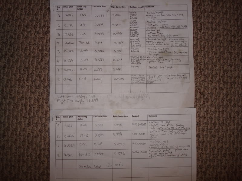
Carrier Shims
Some of the rebuild papers out on the net mention that you need a housing spreader so you can preload the carrier bearings. This tool is not necessary; there is a technique to this. If you are using new gears, then you will have to figure out what total amount of shims is good for the carrier before you actually preload the bearings, let me explain. When you get your carrier shims, there should be a few 0.005 shims in the kit. Set two of those aside and do not touch them until ready for final setup. What you need to do is experiment with the shim packs to get the right fit before preload. The carrier should fit nice and snug in the housing. You should have to tap the last shim pack into the housing. If you can remove the carrier using your hands with little effort, then you need to increase the shims. It should require effort to remove it from the housing. Once you figure out what amount of shims is required before bearing preload, then you are ready to start setting up the gear pattern. You’ll notice if you look at my chart closely, that halfway through the patterning process I realized that my carrier shims were not tight enough in the housing before preload. I had to change the amount of shims during setup – I just saved you from going through this issue. Only once you are done patterning, then you preload each shim pack using one 0.005’’ shim (remember the two you set aside at the beginning?). The type of shim packs that you want have a lip on one side of them. It sandwiches the shims in-between two thick metal discs. These are the ones you want. Once you figure out how many shims you actually need before preload, mark each side’s large metal discs using a sharpie. You don’t want to mix these up during setup. Again, in a perfect world, it wouldn’t matter because they would be the exact same – but, this isn’t a perfect world and you want to eliminate all sources of error when setting up the pattern.
One shim pack:
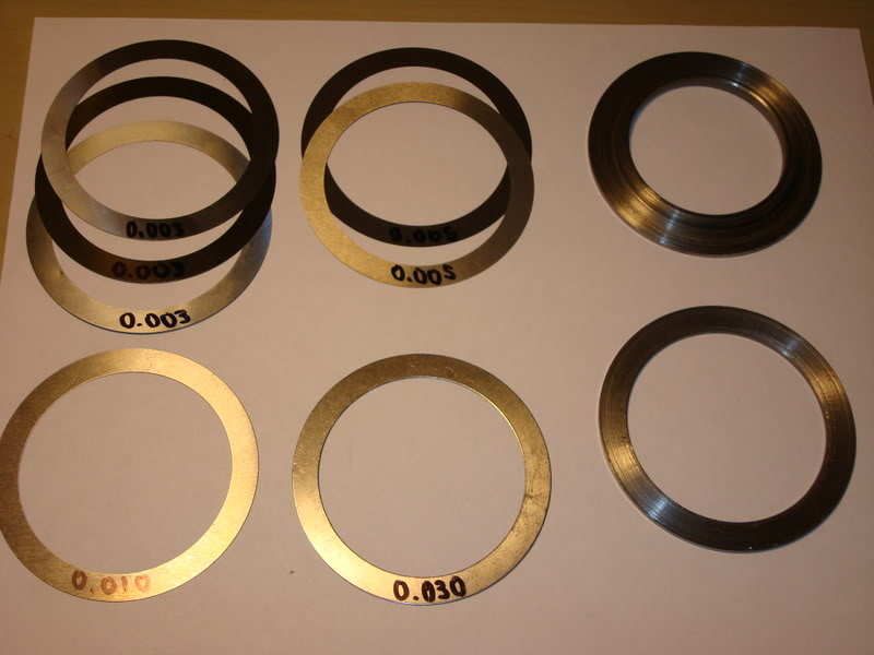
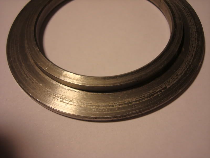
Terminology
Backlash – The play or loose motion in an instrument due to the clearance existing between mechanically contacting parts
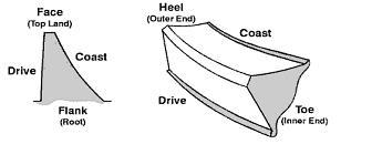
Textbook Patterns
Sometimes you can’t get a perfect “textbook pattern” like you see on the net. Just remember – pinion depth always takes precedence over gear pattern. So if you can’t get the perfect textbook pattern, then work off of the pinion depth in the tooth. This is the most important aspect in the gear patterning procedure – a mistake make here will cause your gears to whine and wear abnormally fast.
Gear Paste
Some of the kits that are sold come with a small amount of paste. You’ll use it fast. Go to your local GM dealer and get some of the yellow stuff. Put it in a medicine bottle and mix some oil in with it until it looks something like this…
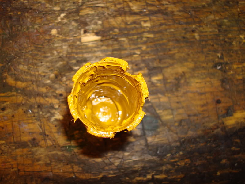
You’ll need to also get a fine bristle paint brush to paint the gear teeth with.
Pinion Flange Inspection
Pinion seal leaks are very common with differentials. Unfortunately, all pinion seals eventually leak, it’s just a matter of time. To prevent this from occurring any time soon, you need to take precautions to not scratch up the pinion seal flange. Look around the pinion seal area for any signs of pitting or scratching. Here is a picture of a really bad one:
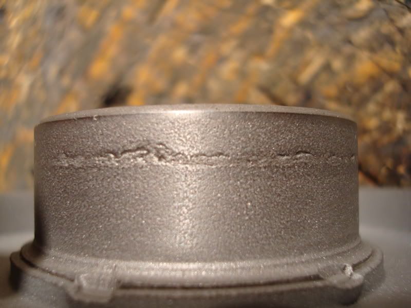
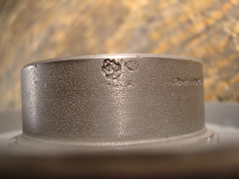
The pinion flange above will leak like a sieve. You might be able to fix your pinion flange using a speedy sleeve from SKF. It’s basically an extremely thin collar that you put on top of the sealing area. The OD becomes a little larger, but they work great. Do not overlook this part, because you will be kicking yourself in the butt every time you look under the car and see gear oil on the ground. It’s better to fix this now, because it will be a pain to fix once you install the diff in the car. The OD of the pinion seal area should be 1.739’’.
To keep yourself organized throughout the patterning, you will need to make yourself a patterning chart. Here is what mine looked like during my setup.
Carrier Shims
Some of the rebuild papers out on the net mention that you need a housing spreader so you can preload the carrier bearings. This tool is not necessary; there is a technique to this. If you are using new gears, then you will have to figure out what total amount of shims is good for the carrier before you actually preload the bearings, let me explain. When you get your carrier shims, there should be a few 0.005 shims in the kit. Set two of those aside and do not touch them until ready for final setup. What you need to do is experiment with the shim packs to get the right fit before preload. The carrier should fit nice and snug in the housing. You should have to tap the last shim pack into the housing. If you can remove the carrier using your hands with little effort, then you need to increase the shims. It should require effort to remove it from the housing. Once you figure out what amount of shims is required before bearing preload, then you are ready to start setting up the gear pattern. You’ll notice if you look at my chart closely, that halfway through the patterning process I realized that my carrier shims were not tight enough in the housing before preload. I had to change the amount of shims during setup – I just saved you from going through this issue. Only once you are done patterning, then you preload each shim pack using one 0.005’’ shim (remember the two you set aside at the beginning?). The type of shim packs that you want have a lip on one side of them. It sandwiches the shims in-between two thick metal discs. These are the ones you want. Once you figure out how many shims you actually need before preload, mark each side’s large metal discs using a sharpie. You don’t want to mix these up during setup. Again, in a perfect world, it wouldn’t matter because they would be the exact same – but, this isn’t a perfect world and you want to eliminate all sources of error when setting up the pattern.
One shim pack:
Terminology
Backlash – The play or loose motion in an instrument due to the clearance existing between mechanically contacting parts
Textbook Patterns
Sometimes you can’t get a perfect “textbook pattern” like you see on the net. Just remember – pinion depth always takes precedence over gear pattern. So if you can’t get the perfect textbook pattern, then work off of the pinion depth in the tooth. This is the most important aspect in the gear patterning procedure – a mistake make here will cause your gears to whine and wear abnormally fast.
Gear Paste
Some of the kits that are sold come with a small amount of paste. You’ll use it fast. Go to your local GM dealer and get some of the yellow stuff. Put it in a medicine bottle and mix some oil in with it until it looks something like this…
You’ll need to also get a fine bristle paint brush to paint the gear teeth with.
Pinion Flange Inspection
Pinion seal leaks are very common with differentials. Unfortunately, all pinion seals eventually leak, it’s just a matter of time. To prevent this from occurring any time soon, you need to take precautions to not scratch up the pinion seal flange. Look around the pinion seal area for any signs of pitting or scratching. Here is a picture of a really bad one:
The pinion flange above will leak like a sieve. You might be able to fix your pinion flange using a speedy sleeve from SKF. It’s basically an extremely thin collar that you put on top of the sealing area. The OD becomes a little larger, but they work great. Do not overlook this part, because you will be kicking yourself in the butt every time you look under the car and see gear oil on the ground. It’s better to fix this now, because it will be a pain to fix once you install the diff in the car. The OD of the pinion seal area should be 1.739’’.
03-30-2008, 07:12 AM
#5
Safety Car
Thread Starter
How to Measure Backlash
For this job you will need to buy another tool – a dial indicator and base. Now, I usually don’t skimp on tools, but here is what I did. Instead of going out and buying one of those really crappy Chinese ones, I decided to get mine from Acklands Grainger, who sells just about all the high end name brands out there. It has a lifetime warranty on it and is much better than those crappy Chinese ones you see at princess auto all the time. Then again, it isn’t the best brand out there - it is Westward (which is Acklands’ brand of tools). It works great for the price, but it probably won’t last me anywhere near as long as a Starrett dial indicator and base would. If you plan on rebuilding these diffs everyday, go out and spent the cash on a really good set. If you plan on using it once in a while, then at least buy yourself one which is better than those cheap Chinese ones. I think I spent $70 for the set, and I have used it to even setup my trailing arm bearings.
The first thing you want to do is drill a hole in a small metal plate which you can use as a support for the indicator base. You will use one bolt in the diff cover holes that are tapped in the housing to hold the plate tight and prevent it from moving. You set the indicator on the top of the tooth, trying to keep perpendicular to the tooth. Push down on the ring gear until the gear contacts the pinion mesh. Now you can set the indicator to zero, and then slightly push the ring gear until the teeth contact the other side of the pinion mesh (don’t turn the pinion, just push the gear until it contacts the pinion again). This “play” is what we call gear backlash. The measurements will vary from tooth to tooth, so you need to measure several teeth in different areas to find out what the lowest number is. They will vary about 0.003’’-0.004’’. The tolerances are different for each gear brand, so check the specs. If using Tom’s gears, set the minimum backlash to 0.005 and nothing less. Once the gears heat up under use, the backlash will close up because the gears will expand. If you set the backlash too tight, then you may cause some excessive wear on the gears. During setup, measure a minimum of 4 different places for backlash. When you think you are done with the setup bearings, measure the backlash of like every 3rd tooth. Yes, this is vette OCD at its finest.
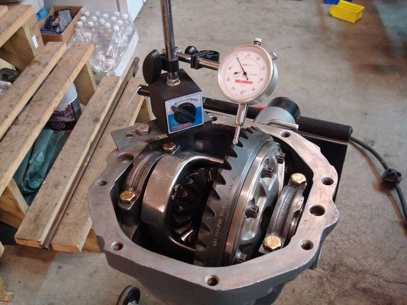
How to Gear Pattern
Go out and buy yourself a cheap box-end wrench (I think the size is 7/16’’). You will be using it to turn the ring gear by its bolts while you load up the pinion flange with a rag. Paint both the coast and drive side of 5 teeth in a couple places on the ring gear. The next thing you do is load up the pinion flange with a rag and turn the ring gear in both directions using the ring gear bolts. You should have to lean into the wrench to turn the ring gear. This is important – if you don’t apply enough braking action to the pinion flange, then your pattern won’t fully show on the teeth, and it may be slightly different than what the paste actually shows.
Start off with the same size pinion shim you removed from the original pinion. Don’t reuse the old one, use the new one in the kit you bought. Remember the shim packs you designated before so the carrier was nice and snug in the housing before preload? Well, now you don’t have to mess around with the amount of shims you need in total before preload, because you did it before. To start off, use more shims on the right side of the housing than on the left side of the housing. This is ball parking the backlash. Install the carrier in the housing very carefully and measure the backlash. If it is too much, then that means that the left side needs another shim. DO NOT JUST ADD ANOTHER SHIM TO THE LEFT SIDE! You have already designated the amount of shims in total to use throughout the patterning. If you need another shim on the left side, then take one out of the right shim pack and add it to the left side. If you need more shims on the right side, take one shim out of the left side and add it to the right side. Or, you could even swap shims from side to side to get a much smaller difference. The smallest shims in the kit are 0.003’’ in thickness, but it you only want to move the ring gear let’s say 0.002’’ away from the pinion, then you could swap the left side’s 0.005 shim for the right side’s 0.003 shim. There should be no need for the extra shims in the kit you bought.
Setup the bearing preload just like you would during final setup, but don’t use the crush sleeve. If you need to change the pinion shim size, remove the carrier, then install that homemade tool you made at the disassembly stage of the rebuild to support the pinion while you remove the outer bearing. Don’t hammer the outer bearing out, use your press to push on the pinion end to pop out the pinion from the housing.
After I got the pattern where I wanted it, I installed the real bearings without the crush sleeve (you have to be extremely careful that you don’t ruin them – remember what I said about setup bearings messing with your torque wrench readings during setup? Well, these are the real bearings and you need a consistent torque reading). Another pattern check just to make sure nothing changed before I installed everything else, and now the pattern went too deep to the root of the ring gear. I had to change the pinion shim size to a 0.024 shim. So I tore everything apart again and pressed off the large pinion bearing very carefully, then installed the 0.024 shim and put everything back together this time with the crush sleeve, pinion seal and permatex sealant on the splines and OD of the seal. Now the damn torque wrench reading was all over the place. I got so frustrated that I squirted lots of oil down to the pinion bearings hoping that would fix the problem. Guess what, now the permatex didn’t dry due to the oil that contaminated it! I didn’t like the stuff in the first place anyways. So, either I ruined the inner bearing when I pressed it off or something else fouled with the readings on the wrench. Either way I needed to get myself another two brand new Timken bearings and a new pinion seal. I marked the pinion nut and pinion end before I removed it so I knew when I hit bottom with the new bearings I was installing – I was going to attempt to use my newly crushed sleeve. This time everything went well. I cleaned both new bearings with brake cleaner and lightly oiled them with 90 weight gear oil. I cleaned the races extremely good and installed the crush sleeve into the housing, then slipped the new pinion (with its inner bearing already pressed) on through the crush sleeve and worked the bearing into the race. I then installed my homemade pinion holder, turn the unit upside down and lightly tapped on the outer bearing. The next thing I did was use q-tips to clean the housing ID where the pinion seal goes with brake cleaner. I also cleaned the pinion splines with brake cleaner on q-tips. Don’t contaminate the outer bearing with the brake cleaner – this is why I used q-tips. Once extremely clean, clean the OD of the pinion seal with brake cleaner/q-tips. Grease the inside of the seal where the spring is, but don’t contaminate the outside of the seal where the RTV silicone will be going. Make sure to grease The id of the seal where the pinion flange runs on, this will affect bearing preload. Install the seal into the housing using RTV on the OD of the seal (don’t put any on the ID of the housing). Read Gary’s thread on installing the pinion seal, he covers how far they need to be installed. Inject RTV around the gap where the seal sits (you read Gary’s post, right?) and wipe it clean with your finger. This prevents any oil from weeping out. Clean the splines of the pinion flange, and use some RTV silicone (loctite makes some really good stuff in a caulking tube, that’s what I used this time around) to cover only the splines. Don’t get any on the base of the flange, or it will get on the outer bearing. Don’t put any directly on the pinion splines either, just put it on the flange splines. You don’t want to get anything on the bearing. Push the flange onto the pinion. Place the washer onto the stuff that oozed out from the top and setup the preload, but this time you’re going to have to go very, very slow and not overcrush the sleeve. It starts to crush real fast after you reach a certain threshold. LET IT SIT WITH THE PINION FLANGE POINTING UP FOR 24 HOURS! LET THE RTV DRY Clean the carrier bearing cap holes with brake cleaner. Once the preload is set, then you can preload each of the shim packs for each side of the carrier with the 0.005’’ shims you set aside at the beginning of the rebuild. Do one more last pattern check. Here is mine (professionally approved by Gary and Mike lol).
pinion drag - 16-18.5 in/lbs
backlash - 0.006-0.008
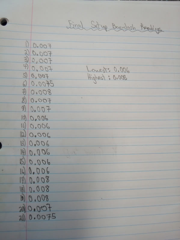
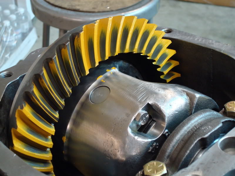
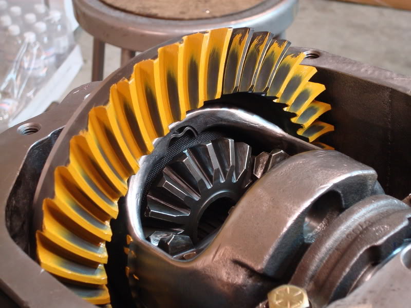
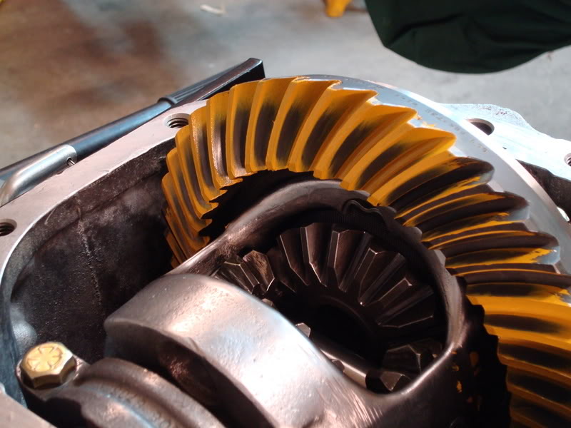
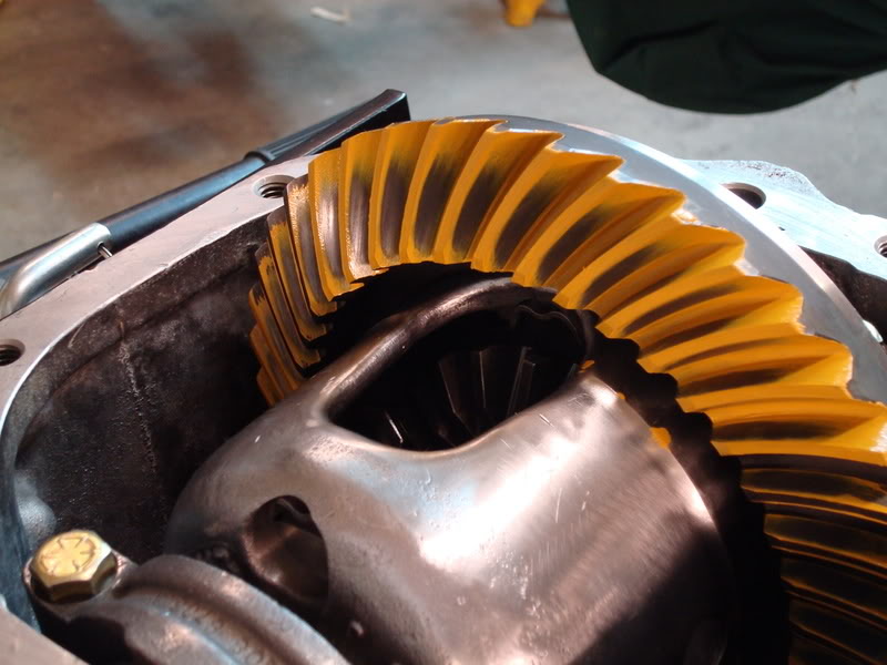
Use some 242 loctite and socket head cap screws for the final install. Let the loctite dry overnight before adding any oil. Before you fit the side yoke seals and bearings, check inside where the yokes enter the housing for metal shards. The shims packs you tapped in might have left some very small metal shavings inside the yoke holes, which could ruin the bearings if left untouched. Grease the roller bearings with high temp grease and install with an appropriate sized socket.
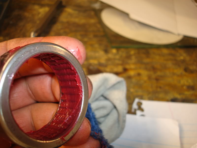
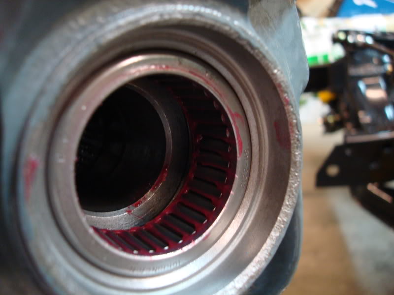
Grease the seal ID and the backside of it as well…
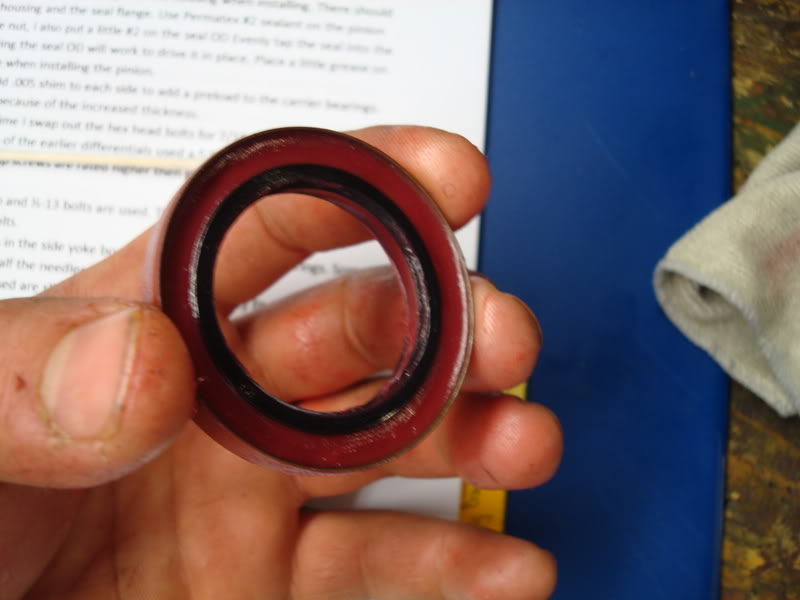
Then use a socket to tap it into the side of the housing.
Fitting the Side Yokes
Okay, so this is the last step – fitting the side yokes. Place the yokes in both sides of the housing and put the snap rings on. Pull the yoke to the side and try fitting a feeler gauge in-between the cross shaft and yoke end. You want 0.005-0.009 endplay. This will allow oil to get around the end of the yoke. It depends on the housing, but technically if you shimmed the posi unit properly, then you won’t have that much endplay. If you need to open up the endplay on a yoke, do the following. Paint the end with layout fluid and then use a really fine sandpaper flapper wheel on an angle grinder just to touch up the ends until the dykem is gone. Be extremely careful not to remove too much material, or you just pissed away a hundred bucks.
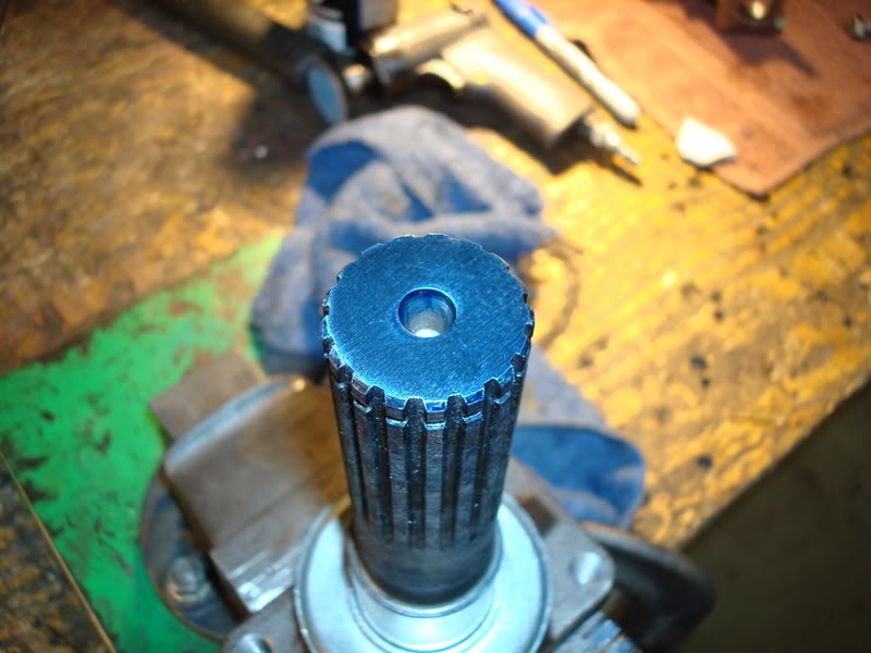
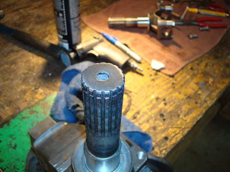
Gear Oil
-2 bottles of GM limited slip additive
-2 bottles of Lucas 85-140 gear oil
The final product (use a gasket and coat both sides with rtv silicone when you install it, only a small bead on each side)…
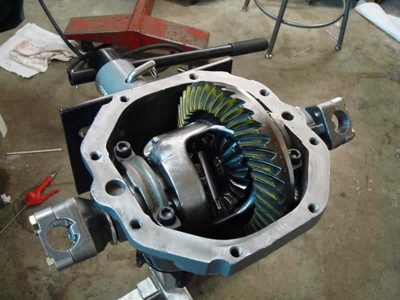
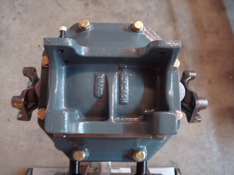
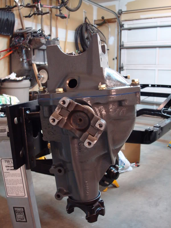
For this job you will need to buy another tool – a dial indicator and base. Now, I usually don’t skimp on tools, but here is what I did. Instead of going out and buying one of those really crappy Chinese ones, I decided to get mine from Acklands Grainger, who sells just about all the high end name brands out there. It has a lifetime warranty on it and is much better than those crappy Chinese ones you see at princess auto all the time. Then again, it isn’t the best brand out there - it is Westward (which is Acklands’ brand of tools). It works great for the price, but it probably won’t last me anywhere near as long as a Starrett dial indicator and base would. If you plan on rebuilding these diffs everyday, go out and spent the cash on a really good set. If you plan on using it once in a while, then at least buy yourself one which is better than those cheap Chinese ones. I think I spent $70 for the set, and I have used it to even setup my trailing arm bearings.
The first thing you want to do is drill a hole in a small metal plate which you can use as a support for the indicator base. You will use one bolt in the diff cover holes that are tapped in the housing to hold the plate tight and prevent it from moving. You set the indicator on the top of the tooth, trying to keep perpendicular to the tooth. Push down on the ring gear until the gear contacts the pinion mesh. Now you can set the indicator to zero, and then slightly push the ring gear until the teeth contact the other side of the pinion mesh (don’t turn the pinion, just push the gear until it contacts the pinion again). This “play” is what we call gear backlash. The measurements will vary from tooth to tooth, so you need to measure several teeth in different areas to find out what the lowest number is. They will vary about 0.003’’-0.004’’. The tolerances are different for each gear brand, so check the specs. If using Tom’s gears, set the minimum backlash to 0.005 and nothing less. Once the gears heat up under use, the backlash will close up because the gears will expand. If you set the backlash too tight, then you may cause some excessive wear on the gears. During setup, measure a minimum of 4 different places for backlash. When you think you are done with the setup bearings, measure the backlash of like every 3rd tooth. Yes, this is vette OCD at its finest.
How to Gear Pattern
Go out and buy yourself a cheap box-end wrench (I think the size is 7/16’’). You will be using it to turn the ring gear by its bolts while you load up the pinion flange with a rag. Paint both the coast and drive side of 5 teeth in a couple places on the ring gear. The next thing you do is load up the pinion flange with a rag and turn the ring gear in both directions using the ring gear bolts. You should have to lean into the wrench to turn the ring gear. This is important – if you don’t apply enough braking action to the pinion flange, then your pattern won’t fully show on the teeth, and it may be slightly different than what the paste actually shows.
Start off with the same size pinion shim you removed from the original pinion. Don’t reuse the old one, use the new one in the kit you bought. Remember the shim packs you designated before so the carrier was nice and snug in the housing before preload? Well, now you don’t have to mess around with the amount of shims you need in total before preload, because you did it before. To start off, use more shims on the right side of the housing than on the left side of the housing. This is ball parking the backlash. Install the carrier in the housing very carefully and measure the backlash. If it is too much, then that means that the left side needs another shim. DO NOT JUST ADD ANOTHER SHIM TO THE LEFT SIDE! You have already designated the amount of shims in total to use throughout the patterning. If you need another shim on the left side, then take one out of the right shim pack and add it to the left side. If you need more shims on the right side, take one shim out of the left side and add it to the right side. Or, you could even swap shims from side to side to get a much smaller difference. The smallest shims in the kit are 0.003’’ in thickness, but it you only want to move the ring gear let’s say 0.002’’ away from the pinion, then you could swap the left side’s 0.005 shim for the right side’s 0.003 shim. There should be no need for the extra shims in the kit you bought.
Setup the bearing preload just like you would during final setup, but don’t use the crush sleeve. If you need to change the pinion shim size, remove the carrier, then install that homemade tool you made at the disassembly stage of the rebuild to support the pinion while you remove the outer bearing. Don’t hammer the outer bearing out, use your press to push on the pinion end to pop out the pinion from the housing.
After I got the pattern where I wanted it, I installed the real bearings without the crush sleeve (you have to be extremely careful that you don’t ruin them – remember what I said about setup bearings messing with your torque wrench readings during setup? Well, these are the real bearings and you need a consistent torque reading). Another pattern check just to make sure nothing changed before I installed everything else, and now the pattern went too deep to the root of the ring gear. I had to change the pinion shim size to a 0.024 shim. So I tore everything apart again and pressed off the large pinion bearing very carefully, then installed the 0.024 shim and put everything back together this time with the crush sleeve, pinion seal and permatex sealant on the splines and OD of the seal. Now the damn torque wrench reading was all over the place. I got so frustrated that I squirted lots of oil down to the pinion bearings hoping that would fix the problem. Guess what, now the permatex didn’t dry due to the oil that contaminated it! I didn’t like the stuff in the first place anyways. So, either I ruined the inner bearing when I pressed it off or something else fouled with the readings on the wrench. Either way I needed to get myself another two brand new Timken bearings and a new pinion seal. I marked the pinion nut and pinion end before I removed it so I knew when I hit bottom with the new bearings I was installing – I was going to attempt to use my newly crushed sleeve. This time everything went well. I cleaned both new bearings with brake cleaner and lightly oiled them with 90 weight gear oil. I cleaned the races extremely good and installed the crush sleeve into the housing, then slipped the new pinion (with its inner bearing already pressed) on through the crush sleeve and worked the bearing into the race. I then installed my homemade pinion holder, turn the unit upside down and lightly tapped on the outer bearing. The next thing I did was use q-tips to clean the housing ID where the pinion seal goes with brake cleaner. I also cleaned the pinion splines with brake cleaner on q-tips. Don’t contaminate the outer bearing with the brake cleaner – this is why I used q-tips. Once extremely clean, clean the OD of the pinion seal with brake cleaner/q-tips. Grease the inside of the seal where the spring is, but don’t contaminate the outside of the seal where the RTV silicone will be going. Make sure to grease The id of the seal where the pinion flange runs on, this will affect bearing preload. Install the seal into the housing using RTV on the OD of the seal (don’t put any on the ID of the housing). Read Gary’s thread on installing the pinion seal, he covers how far they need to be installed. Inject RTV around the gap where the seal sits (you read Gary’s post, right?) and wipe it clean with your finger. This prevents any oil from weeping out. Clean the splines of the pinion flange, and use some RTV silicone (loctite makes some really good stuff in a caulking tube, that’s what I used this time around) to cover only the splines. Don’t get any on the base of the flange, or it will get on the outer bearing. Don’t put any directly on the pinion splines either, just put it on the flange splines. You don’t want to get anything on the bearing. Push the flange onto the pinion. Place the washer onto the stuff that oozed out from the top and setup the preload, but this time you’re going to have to go very, very slow and not overcrush the sleeve. It starts to crush real fast after you reach a certain threshold. LET IT SIT WITH THE PINION FLANGE POINTING UP FOR 24 HOURS! LET THE RTV DRY Clean the carrier bearing cap holes with brake cleaner. Once the preload is set, then you can preload each of the shim packs for each side of the carrier with the 0.005’’ shims you set aside at the beginning of the rebuild. Do one more last pattern check. Here is mine (professionally approved by Gary and Mike lol).
pinion drag - 16-18.5 in/lbs
backlash - 0.006-0.008
Use some 242 loctite and socket head cap screws for the final install. Let the loctite dry overnight before adding any oil. Before you fit the side yoke seals and bearings, check inside where the yokes enter the housing for metal shards. The shims packs you tapped in might have left some very small metal shavings inside the yoke holes, which could ruin the bearings if left untouched. Grease the roller bearings with high temp grease and install with an appropriate sized socket.
Grease the seal ID and the backside of it as well…
Then use a socket to tap it into the side of the housing.
Fitting the Side Yokes
Okay, so this is the last step – fitting the side yokes. Place the yokes in both sides of the housing and put the snap rings on. Pull the yoke to the side and try fitting a feeler gauge in-between the cross shaft and yoke end. You want 0.005-0.009 endplay. This will allow oil to get around the end of the yoke. It depends on the housing, but technically if you shimmed the posi unit properly, then you won’t have that much endplay. If you need to open up the endplay on a yoke, do the following. Paint the end with layout fluid and then use a really fine sandpaper flapper wheel on an angle grinder just to touch up the ends until the dykem is gone. Be extremely careful not to remove too much material, or you just pissed away a hundred bucks.
Gear Oil
-2 bottles of GM limited slip additive
-2 bottles of Lucas 85-140 gear oil
The final product (use a gasket and coat both sides with rtv silicone when you install it, only a small bead on each side)…
Last edited by stinger12; 03-30-2008 at 10:56 AM.


 03-30-2008, 07:43 AM
#7
Pro

Thanks for taking the time to document and post this paper Jeremy. Super job, very useful.


 03-30-2008, 11:54 AM
#12
Safety Car
Thread Starter

The following users liked this post:
EarlyC34me (05-08-2017)
03-30-2008, 06:41 PM
#13
Tech Contributor

Nice job Jeremy, my star student!!!
You built a very good unit that few would attempt to do and one in which there are probably less then a finger count that could/would build it like that.
You built a very good unit that few would attempt to do and one in which there are probably less then a finger count that could/would build it like that.
The following users liked this post:
DorianC3 (10-21-2019)
03-30-2008, 06:49 PM
#14
Safety Car
Thread Starter
Thanks Gary. I just realized that I accidentally left out the brass drain plug that I installed...I'll have to find those pics somewhere on my computer.
03-30-2008, 06:51 PM
#15
Race Director

Nice job. I saved this along with Garys paper. Gary helped me do mine 2 years ago and it is holding up fine so far. My only suggestion is when you put on the ring gear I would not bring the ring gear on with an impact gun. I bring the ring gear on with a long bar and socket. This way if there is any interference or problem I can stop and figure it out. The chances of that happening are slim but I'd hate to screw up the ring gear or the case. I don't like impact guns for assembly work. 
03-30-2008, 07:01 PM
#16
Safety Car
Thread Starter
Me neither. I originally used a dead blow hammer to install the ring gear, but that took forever so I said screw it and took out the impact I could probably build a diff in less than a week now if I had all the parts I needed...it's not even a feat for me anymore. Piece of cake, now bring on the tranny build
I could probably build a diff in less than a week now if I had all the parts I needed...it's not even a feat for me anymore. Piece of cake, now bring on the tranny build
03-30-2008, 07:38 PM
#17
Race Director
Me neither. I originally used a dead blow hammer to install the ring gear, but that took forever so I said screw it and took out the impact I could probably build a diff in less than a week now if I had all the parts I needed...it's not even a feat for me anymore. Piece of cake, now bring on the tranny build
I could probably build a diff in less than a week now if I had all the parts I needed...it's not even a feat for me anymore. Piece of cake, now bring on the tranny build


 03-30-2008, 10:12 PM
#20

Just reading down through this quickly (I'll look at it harder when I am more awake) -
Re: Fitting the side yokes
I've been running 1 - 1 1/2 thou clearance on both sides for a number of years without any trouble. I don't see the need for more clearance than that as it is a low speed application and there is admirably good access to the line of contact for the grease. I also like the idea of having minimal wobble in what, in these cars, is an upper contol arm.
As far as using a flapper wheel to trim off the ends . . . not what I'd call precision work. I'm sure it can be done close enough to be successful, but keeping the end perfectly perpendicular to the axis of rotation seems like a pretty good idea.
I'd also be concerned with going through the case hardening. Not sure how deep it runs in current aftermarket stuff, but it seems to have been GD thin in the stock pieces from years ago.
/machinist by trade, probably nitpicking
Good write-up w/good photos, you clearly put some time, effort and thought into the build + this write-up. It shows.
//won't forget, years ago, seeing damned near .060" endplay in my side yokes. My head almost exploded.