
Vacuum Diagram for a 1977 Coupe
 04-01-2008, 12:51 PM
#1
Burning Brakes

Thread Starter
Hello,
Does anyone have a Vac. Diagram for a 1977 Coupe kicking around they can email me?
I wanna double check some vac lines and my books that I have are not really clear about it.
Thanks for your help in advance.
Jimbo
Does anyone have a Vac. Diagram for a 1977 Coupe kicking around they can email me?
I wanna double check some vac lines and my books that I have are not really clear about it.
Thanks for your help in advance.
Jimbo
 04-01-2008, 01:23 PM
#2
Burning Brakes
Thread Starter
Sure does, thanks! I am also looking for the vac diagram for the heating system. My car was orinally an A/C car but most of the stuff was removed by the previouse owner so I am trying to figure that out.
thanks
Jimbo
thanks
Jimbo
 04-01-2008, 01:50 PM
#5
Safety Car

Member Since: Oct 2007
Location: Seattle Area Washington
Posts: 3,663
Received 1,292 Likes
on
1,012 Posts


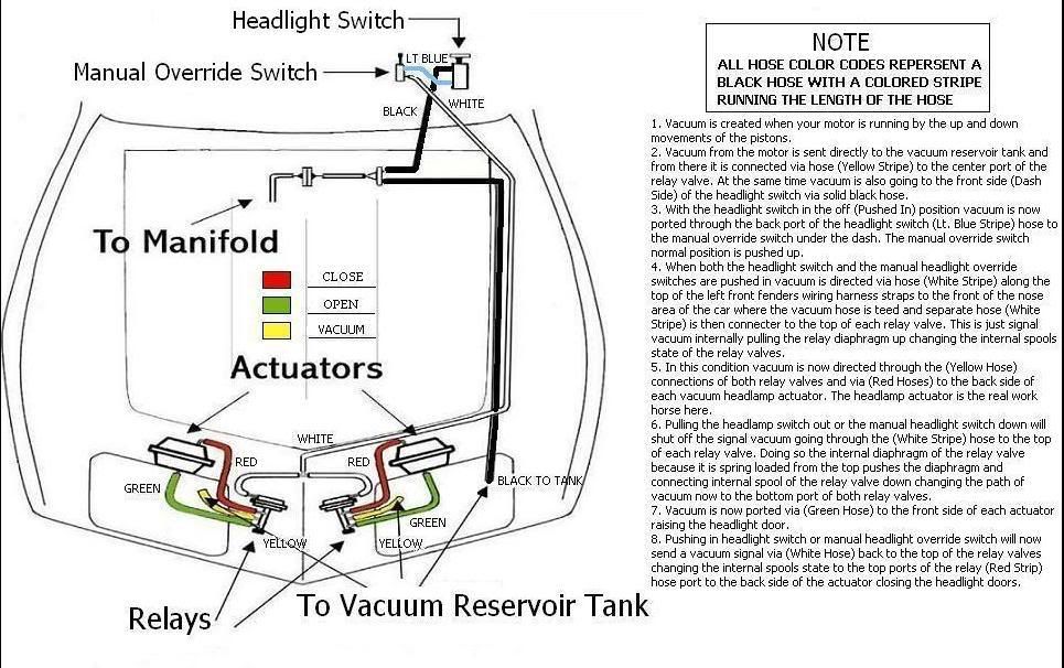
Sorry but the vacuum diagram provided by Corvette 101 is not correct. The headlight vacuum lines are wrong. The upper connection of the manual pull down switch goes directly to the top port of the headlight switch, not directly to the actuator tee. The bottom port of the manual pull down switch goes directly to the actuator tee. Other then that the drawing is correct.
04-01-2008, 01:54 PM
#6
Team Owner

Member Since: Aug 2006
Location: Columbia Missouri
Posts: 24,125
Likes: 0
Received 9 Likes
on
9 Posts
Sorry but the vacuum diagram provided by Corvette 101 is not correct. The headlight vacuum lines are wrong. The upper connection of the manual pull down switch goes directly to the top port of the headlight switch, not directly to the actuator tee. The bottom port of the manual pull down switch goes directly to the actuator tee. Other then that the drawing is correct.
Yeah you'll notice I fixed it in the one I posted. Go to the website and you'll see the change I made...unless they fixed the one on the 101 website, and I already had the correct one and just made it wrong again.
04-01-2008, 02:16 PM
#7
Burning Brakes
Thread Starter
Ok, Thanks for the heads up.
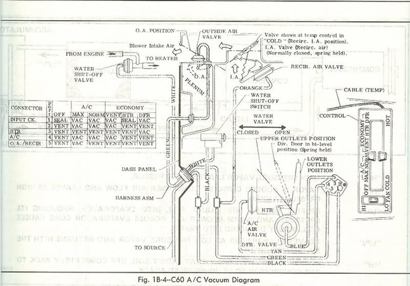
I am really trying to figure out how to get my heat and vents to work without any of the A/C stuff attached. The previous owner pulled the compressor, lines and gutted the box on the pass. side engine bay.
So i gotta figure out the HVAC panel in the car and how it will relate to the vents and also the vac. valve thats on the line going to the heater core.
Any suggestions?
I dont care that the A/C is gone, thats what T-tops are for!!
Just want the heat and vents to work somewhat correct.
Thanks agian
Jimbo
04-01-2008, 02:30 PM
#8
Safety Car
Member Since: Oct 2007
Location: Seattle Area Washington
Posts: 3,663
Received 1,292 Likes
on
1,012 Posts
I believe this is a correct drawing for the headlights. Complete with color coded lines as they were installed at the factory.
04-01-2008, 02:41 PM
#9
Safety Car
Member Since: Oct 2007
Location: Seattle Area Washington
Posts: 3,663
Received 1,292 Likes
on
1,012 Posts
All of the HVAC lines are color coded that should help using the drawing provided. They may be brittle from age so handle them gently. An inexpensive hand pump that creates a vacuum with gauge will help you isolate bad lines and valves. If you need to splice any lines I suggest getting a larger vacuum line that the ID fits snug on the OD of the original line. I�m not sure if Dr. Rebuild offers replacement lines for the HVAC controls but if he does they should be the best replacement available out there.