
Steering column wiring (harness)
 07-04-2008, 08:44 PM
#1
Melting Slicks

Thread Starter
Hate to even ask, but I have replaced my steering column on my '72 with a tilt/tele one and while the harness plug on the new column and the car both have 10 wires, the color scheme is waaaaay different. I have no idea how to trace the wires and don't want to take the steering column apart for that unless it is absolutely necessary. Think the wiring would be okay? Is there any other way to check this wiring short of doing an autopsy? Thanks. The column is for a '72. Happy 4th!
 07-04-2008, 10:10 PM
#3
Melting Slicks
Thread Starter
Yes, I had to rotate the ign plugs, no problem.... The other harness is the one in question. 10 wires all in a row, colors on column don't match those on the original column....
07-04-2008, 11:13 PM
#4
Le Mans Master


Member Since: Jul 2000
Location: Saginaw Michigan
Posts: 6,001
Likes: 0
Received 98 Likes
on
81 Posts

No problem, the wire colors don't have to match. The wires match up standard (non-adjustable) column or T&T regardless. That flat connector is called a "harmonica" connector. 1969 through 1982 the wires all match up. One change 1980 thru 1982, cornering lights were added to the column wiring. So when swapping one of those later columns into an early car you will have three extra wires. Those three wires in the harmonica connector just won't connect to anything.
There was a slight revision to the plastic connector that sometimes prevents a later column connector from snapping into the body harness on a early car. You can try trimming the connectors to make them fit together. Another option is to remove the connector from the old column and just swap it on the wires in the new column. Just keep the wires in the correct order if you have to make the swap.
If you are interested here is a paper which calls out the column wires, colors, gage of wire, and function.
http://jimshea.corvettefaq.com/wp-co...ires25NO04.doc
Jim
Last edited by Jim Shea; 07-04-2008 at 11:16 PM.
07-06-2008, 02:39 PM
#5
Melting Slicks
Thread Starter
Thanks Jim, that harmonic wiring harness issue is a relief to have behind me. Now, should there be like about 1/2 inch play up and down on the tilt, at any position? Seems like a lot and dangerous to drive with. How hard to correct, can do with column in or must take out? I will look over your papers too. Hope it doesn't have to come out but if it does, I may just send it back...
07-06-2008, 02:49 PM
#6
Le Mans Master
I'll step in about the loose tilt thing- not hard to fix, but you need to take a lot of the upper column apart to do so. Jim's papers have all the stuff on how-to. The problem is that if you don't fix it, it'll keep getting loose and eventually break the ears off the inner tube. 
07-16-2008, 09:20 PM
#8
Melting Slicks
Thread Starter
No problem, the wire colors don't have to match. The wires match up standard (non-adjustable) column or T&T regardless. That flat connector is called a "harmonica" connector. 1969 through 1982 the wires all match up. One change 1980 thru 1982, cornering lights were added to the column wiring. So when swapping one of those later columns into an early car you will have three extra wires. Those three wires in the harmonica connector just won't connect to anything.
There was a slight revision to the plastic connector that sometimes prevents a later column connector from snapping into the body harness on a early car. You can try trimming the connectors to make them fit together. Another option is to remove the connector from the old column and just swap it on the wires in the new column. Just keep the wires in the correct order if you have to make the swap.
If you are interested here is a paper which calls out the column wires, colors, gage of wire, and function.
http://jimshea.corvettefaq.com/wp-co...ires25NO04.doc
Jim
There was a slight revision to the plastic connector that sometimes prevents a later column connector from snapping into the body harness on a early car. You can try trimming the connectors to make them fit together. Another option is to remove the connector from the old column and just swap it on the wires in the new column. Just keep the wires in the correct order if you have to make the swap.
If you are interested here is a paper which calls out the column wires, colors, gage of wire, and function.
http://jimshea.corvettefaq.com/wp-co...ires25NO04.doc
Jim
 07-16-2008, 11:06 PM
#9
Drifting

I removed the column so that I could get to the harmonica harness because I could not get it to plug in to the car harness plug. I would like to remove the wires from the plug on the column and switch the plug with the 'old' column plug but cannot figure out how to remove the wires from the harness. Is there a trick to that? I am losing my marbles! Thanks
07-17-2008, 10:19 AM
#10
Le Mans Master
Member Since: Jul 2000
Location: Saginaw Michigan
Posts: 6,001
Likes: 0
Received 98 Likes
on
81 Posts
Here is the description on removing and installing wire in the harmonica connector. This is copied directly from the T&T Disassembly & Repair Paper #2.
Here is the address for the paper: http://jimshea.corvettefaq.com/wp-co...2-30jn2007.doc
Removing and Reinstalling Column Wiring into the Harmonica Connector
Some people have been successful using the following procedure; disengage and remove the individual switch wires and metal contacts from the plastic “harmonica” connector. Straighten a heavy paper clip or use a very thin blade screwdriver. Insert it into the “harmonica” connector from the contact side to disengage each wire and contact. There should be a small molded square channel in the connector that will guide you to a metal tang on the contact that holds it in place. Once you depress the tang and pop the wire and contact out of the connector, you should take a small knife blade and bend the tang back out so that it will engage the connector correctly upon reinstallation. The turn signal switch wiring can now be fed separately through the column.
Jim
Last edited by Jim Shea; 07-17-2008 at 10:21 AM.
07-17-2008, 06:32 PM
#11
Melting Slicks
Thread Starter
Jim, since I am bound to get into the column as far as I need to in order to fix the vertical play in the tilt, should I leave the wires out of the harmonica plug when I (finally) get them out, until I fix the other problem? I have all the wires out now, was pretty easy after knowing how.... Thanks to you and Artsvette. Since the column is out of the car, fix the tilt now, or put column back in first, I am concerned about having to fish the wires.
Last edited by kansas123; 07-17-2008 at 06:53 PM. Reason: condition changed
07-18-2008, 07:40 AM
#12
Le Mans Master
Member Since: Jul 2000
Location: Saginaw Michigan
Posts: 6,001
Likes: 0
Received 98 Likes
on
81 Posts
Fix the tilt now. I have found that it is far easier to fish the wires with the column out of the car anyway. So fix the tilt; then fish the wires; then reinstall your column.
I strongly recommend that you visit www.corvettefaq.com and download my T&T Disassembly & Repair Papers 1, 2, & 3. As well as the three T&T Disassembly & Repair Pics in the Corvette Steering paper section.
Just remember that additional help is just a computer click away.
Jim
I strongly recommend that you visit www.corvettefaq.com and download my T&T Disassembly & Repair Papers 1, 2, & 3. As well as the three T&T Disassembly & Repair Pics in the Corvette Steering paper section.
Just remember that additional help is just a computer click away.
Jim
07-18-2008, 12:34 PM
#13
Melting Slicks
Thread Starter
Fix the tilt now. I have found that it is far easier to fish the wires with the column out of the car anyway. So fix the tilt; then fish the wires; then reinstall your column.
I strongly recommend that you visit www.corvettefaq.com and download my T&T Disassembly & Repair Papers 1, 2, & 3. As well as the three T&T Disassembly & Repair Pics in the Corvette Steering paper section.
Just remember that additional help is just a computer click away.
Jim
I strongly recommend that you visit www.corvettefaq.com and download my T&T Disassembly & Repair Papers 1, 2, & 3. As well as the three T&T Disassembly & Repair Pics in the Corvette Steering paper section.
Just remember that additional help is just a computer click away.
Jim
07-18-2008, 02:08 PM
#14
Melting Slicks
You can also get a plug adapter from Lectric Limited so you don't have to rearrange a single wire.
I installed an 80 tilt/tele column in my 68 vert, and I was able to get a plug adapter from them to link my 68 wiring harness to the 80 column harness. Just plug & play and it gave me 6 inches of additional wire length that I needed.
I installed an 80 tilt/tele column in my 68 vert, and I was able to get a plug adapter from them to link my 68 wiring harness to the 80 column harness. Just plug & play and it gave me 6 inches of additional wire length that I needed.
07-19-2008, 08:10 PM
#15
Melting Slicks
Thread Starter
Fix the tilt now. I have found that it is far easier to fish the wires with the column out of the car anyway. So fix the tilt; then fish the wires; then reinstall your column.
I strongly recommend that you visit www.corvettefaq.com and download my T&T Disassembly & Repair Papers 1, 2, & 3. As well as the three T&T Disassembly & Repair Pics in the Corvette Steering paper section.
Just remember that additional help is just a computer click away.
Jim
I strongly recommend that you visit www.corvettefaq.com and download my T&T Disassembly & Repair Papers 1, 2, & 3. As well as the three T&T Disassembly & Repair Pics in the Corvette Steering paper section.
Just remember that additional help is just a computer click away.
Jim
Maybe the play I have isn't that bad after all ......
 07-19-2008, 11:14 PM
#16
Le Mans Master
Member Since: Jul 2000
Location: Saginaw Michigan
Posts: 6,001
Likes: 0
Received 98 Likes
on
81 Posts
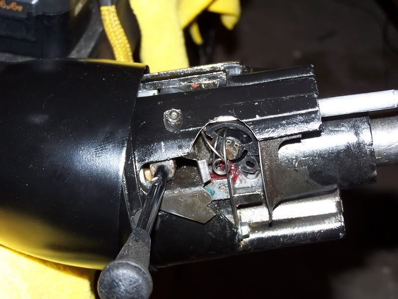
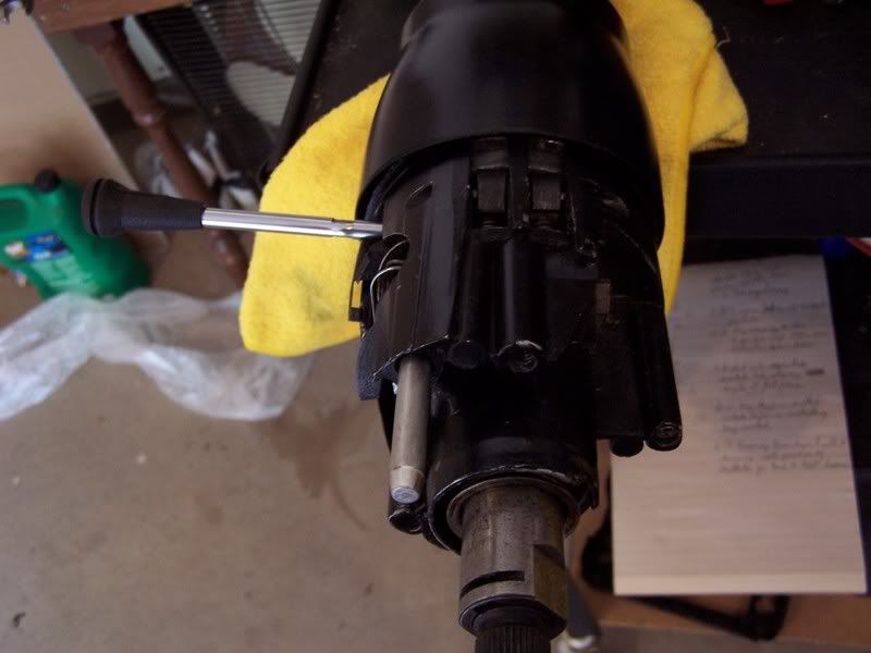
Remove the tilt spring cap and the tilt spring. Then you need to pull the pivot pins. In your first photo the left side pin is partially hidden under the tilt lever. Then you can pull the upper bearing housing off of the steering shaft. You will now have access to the four screws that hold the support to the steering column jacket. Remove the screws individually. Add loctite to the threads and reinstall and tighten each one. Your loose column head is a thing of the past.
Jim
Jim
07-20-2008, 12:07 PM
#17
Melting Slicks
Thread Starter
Remove the tilt spring cap and the tilt spring. Then you need to pull the pivot pins. In your first photo the left side pin is partially hidden under the tilt lever. Then you can pull the upper bearing housing off of the steering shaft. You will now have access to the four screws that hold the support to the steering column jacket. Remove the screws individually. Add loctite to the threads and reinstall and tighten each one. Your loose column head is a thing of the past.
Jim
Jim
and one sorta unrelated question, if I want to use my original ignition key, is there a way to take the key 'guts' from the old switch and put on the new switch? I understand that the two cylinder, switches/locks are not interchangeable between tilt/tele and standard as a unit.... Thanks.
Last edited by kansas123; 07-20-2008 at 01:34 PM. Reason: additional information
07-20-2008, 02:40 PM
#18
Melting Slicks
Thread Starter
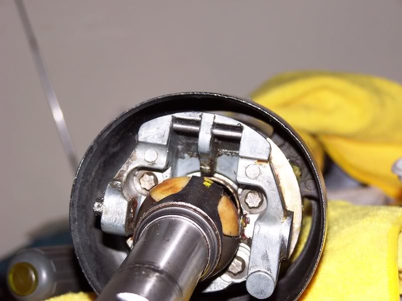
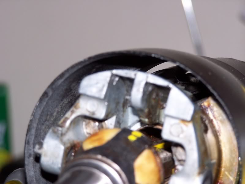
I believe my problem with up/down play in tilt stems from the pin that the shoes index on; the left hole seems to be boogered up a bit, does not allow the pin to go thru it and so, as it just barely sits on the ledge of the hole, it allows the column/shoe to wiggle. Dammit Man! Anyway, what the devil holds that pin in place for one thing. For another, would it hurt anything to drive that pin in from the right so as to get it to pass thru the left side, thereby making it tight again? I reiterate, what should be there to keep the pin in place? In the pictures you see the pin reinstalled, and the second picture you can barely see the boogered up hole. Thanks.
07-20-2008, 07:19 PM
#19
Le Mans Master
Member Since: Jul 2000
Location: Saginaw Michigan
Posts: 6,001
Likes: 0
Received 98 Likes
on
81 Posts
I would expect that the pin should be a press fit through all three holes in the support. Possibly the thing to do is to start pressing the pin into the support through the 'buggered up" hole from the left side.
One other thing, check the lock shoes. They pivot on a pin that is part of the bearing housing. Make sure that the pin is secure and that the shoes pivot with no noticeable slop.
Jim
One other thing, check the lock shoes. They pivot on a pin that is part of the bearing housing. Make sure that the pin is secure and that the shoes pivot with no noticeable slop.
Jim
Last edited by Jim Shea; 07-20-2008 at 07:22 PM.
07-21-2008, 04:52 PM
#20
Melting Slicks

