
another home made Rack and Pinion
 01-03-2010, 08:43 PM
#1
Drifting

Thread Starter
First off I need to give a special thanks to, Vette427 sbc, 69myway,
MRvette, and all other forum members that I may be forgetting.
To do a job like this it takes time which is what I have very little
of but I finely got this far.
I started out getting all my need to know info from the greet
forum members
we have here, thanks guys.
I bought a 98 Grand Am rack and pinion with both brackets and
tie rods. and a 2004 Malibu steering shaft from the local junk yard.
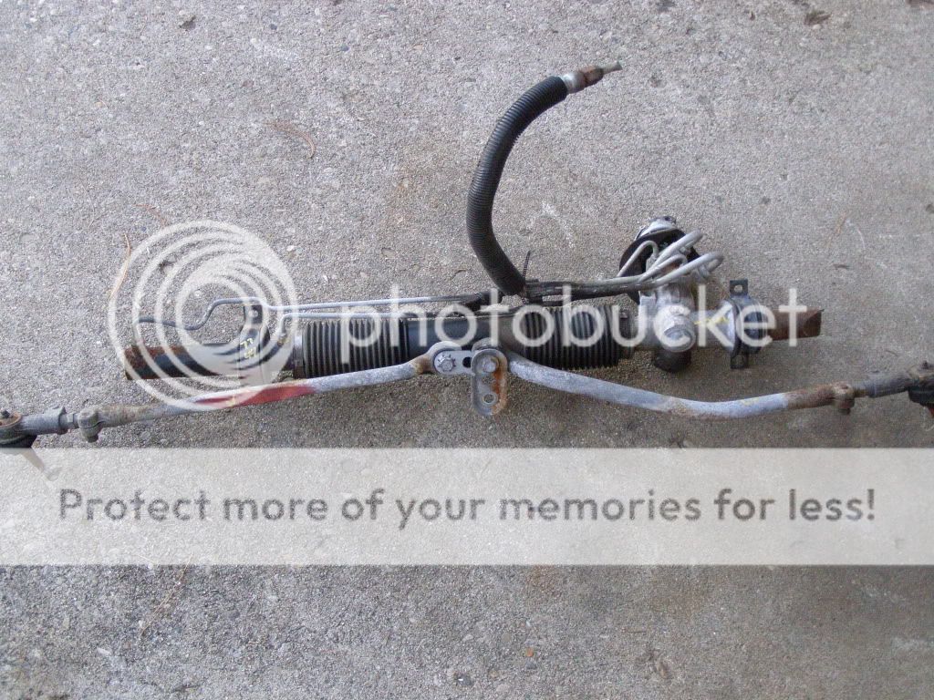

I then bought new Inner and outer tie rods for a Grand Am, They work
out well.
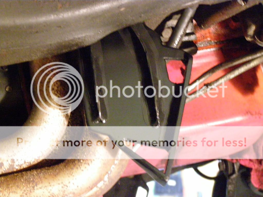
After tearing out the old system, I built the bracket to hold the
rack. I used the original hole in the frame to bolt in the new setup.
The material I used for the brackets is 3/16 flat steel.


I then took the steering column out of the car and altered the
end to except the Malibu steering stem.


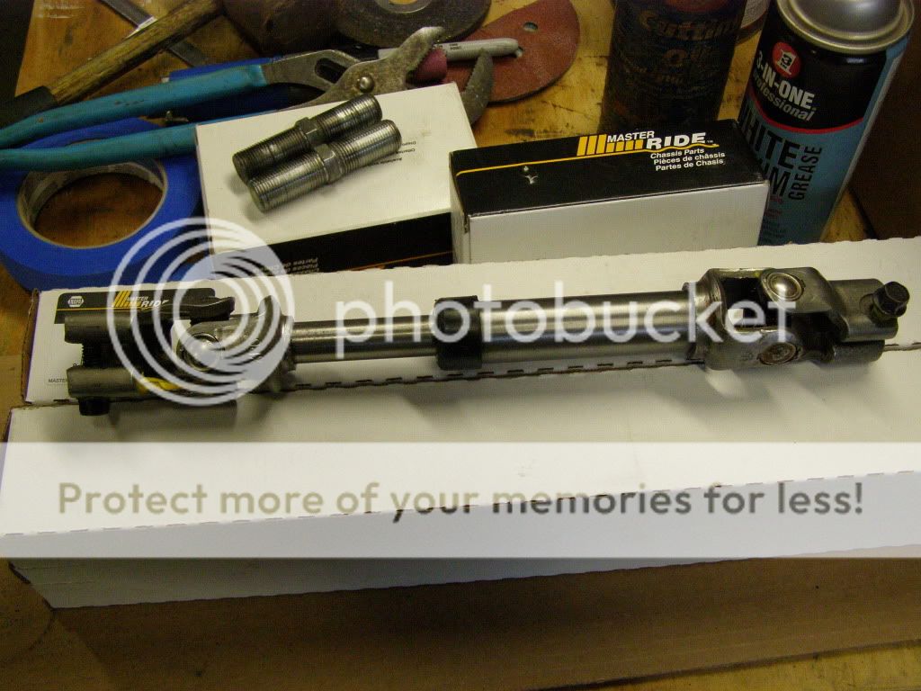
Then reinstalled the column and the steering shaft into the car along with the rack.

I was getting a little resistance when turning the wheel every
1/2 turn so I had to collapse the column alittle, will I went a little
to far and can't pull it back down so I will either extend the steering
shaft or I will get a longer setup.

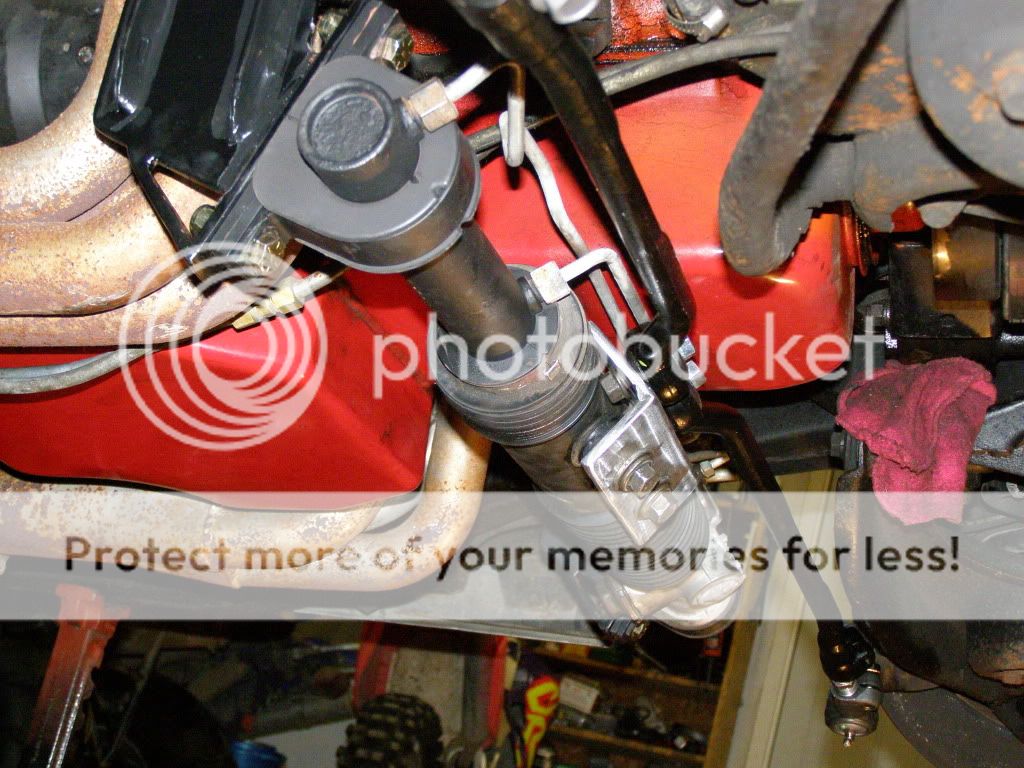
Now I built a center bracket out of 3/16 flat steel cut two pieces
2'' wide by 5'' long welded it at a 75 to 80 degree angle, drilled
for the mounting and tie rod bolts, and installed it and the tie rods.


Every thing is in and looks like it will give me no problem. I am
taking most of this back apart to replace some hard ware and
I am tearing out the control arms to put new bushings and ball
joints in. after all this is done I will align it and give a post on
how it performs and what, if any changes I make. I also have to
get some hoses and I think I,m going to get them from speed direct
for $62 for both hoses.
Thanks to all who has helped.
Riggs.
MRvette, and all other forum members that I may be forgetting.
To do a job like this it takes time which is what I have very little
of but I finely got this far.
I started out getting all my need to know info from the greet
forum members
we have here, thanks guys.
I bought a 98 Grand Am rack and pinion with both brackets and
tie rods. and a 2004 Malibu steering shaft from the local junk yard.
I then bought new Inner and outer tie rods for a Grand Am, They work
out well.
After tearing out the old system, I built the bracket to hold the
rack. I used the original hole in the frame to bolt in the new setup.
The material I used for the brackets is 3/16 flat steel.
I then took the steering column out of the car and altered the
end to except the Malibu steering stem.
Then reinstalled the column and the steering shaft into the car along with the rack.
I was getting a little resistance when turning the wheel every
1/2 turn so I had to collapse the column alittle, will I went a little
to far and can't pull it back down so I will either extend the steering
shaft or I will get a longer setup.
Now I built a center bracket out of 3/16 flat steel cut two pieces
2'' wide by 5'' long welded it at a 75 to 80 degree angle, drilled
for the mounting and tie rod bolts, and installed it and the tie rods.
Every thing is in and looks like it will give me no problem. I am
taking most of this back apart to replace some hard ware and
I am tearing out the control arms to put new bushings and ball
joints in. after all this is done I will align it and give a post on
how it performs and what, if any changes I make. I also have to
get some hoses and I think I,m going to get them from speed direct
for $62 for both hoses.
Thanks to all who has helped.
Riggs.


 01-03-2010, 10:56 PM
#4
Melting Slicks

You do some nice metal work, those mounting brackets to the frame are awsome.
Question, with the angle your rack is mounted it looks like the tire rods won't get to move in a vertical fashion where the wheels will want to move. Might just be the angle of the pictures, but if you're removing the springs to rebuild the A-arm bushings you might want to run the wheels thru full travel and see if the tie rods have any binding.
The way the rack mounts and your Tie-Rod bracket is mounted it looks like the tie rods will move more in a front-to back motion then up and down like the wheels will want to move. Just my observation, could just be the angle of the pics.
Very nice work, the insane hangle of the steering shaft makes me nervous if you were to auto x this car or put it thru any serious performance runs.
 01-04-2010, 06:12 PM
#6
Drifting
Thread Starter
68 NJConv 454,
These pictures were taken with the wheels turned, putting the spindle
end/tie rod to its location you see in the photo. I do believe it will be fine
how ever it would be a great ideal to check the motion once the spring
is out.
That steering stem it not at that bad of an angle now, but before I collapsed the
column it was binding a little to much for my liking.
Riggs.
01-04-2010, 06:48 PM
#7
Melting Slicks
Sounds good. Let us know how the system works out. Again, very impressed with the brackets!
Check out this pic for reference to how vertical the tie-rod mounting bracket needs to be to prevent binding when the wheels go through full travel. http://vetteworksonline.com/steeriod...teeroids4w.jpg
Just want you and your car to be safe. We put a lot of $, blood and sweat into these cars, wouldn't want you to find out it binds at the worst time.
01-04-2010, 06:55 PM
#8
Melting Slicks
Also, if you notice your tie-rod arms are much longer than the pic I posted above. This is a good thing as the longer arms will give you less bumpsteer as the wheels go thru their full vertical range of motion. The shorter the arms the more of an arc when the wheels go from lowest to highest or visaversa. Your longer arms will result in less arc giving you less bump steer.
01-04-2010, 07:24 PM
#9
Drifting
Thread Starter
After looking at the subject again I do see what your talking about now.
You must be referring to the inner tie rod mounting location being on top
and possibly not allowing the tie rod arm to move up and down. I will check
this out when I remove the front springs. I did copy this set up from another
forum member and did not read about that giving him any problem, I will look
into it though.
Thanks for the input,
Edit, After looking some more, I will be making a new center bracket with a different
angle that puts the inner tie rod bolt more horizontal to allow the outer tie rod to travel
up and down.
Thanks 68 Njconv 454 for setting me straight.
Riggs.
Last edited by riggs 74; 01-04-2010 at 08:22 PM.
01-04-2010, 08:33 PM
#10
Team Owner

Riggs, the ensuing conversation made me go back and look again at your senter arm bracket....those bolts holding the tie rods on to the bracket, are they going through a welded nut on back of the bracket, as that bracket on the inside in that area looks too close to the rubber boot, ...
my concern is that there is not enough steel for them to bit into on the bracket itself, and I fail to see clearance for any bolt/reinforcement....


my concern is that there is not enough steel for them to bit into on the bracket itself, and I fail to see clearance for any bolt/reinforcement....
01-04-2010, 08:49 PM
#11
Melting Slicks
01-04-2010, 08:55 PM
#12
Drifting
Thread Starter
No Sir, Those bolts are temporary 3/8'' bolts that will be replaced with
1/2''bolt and nut. There will be more clearence when I make a new center
bracket with less of an angle, so that the inner tie rod bolt will sit more
horizontal for better vertical articulation for the tie rod Assembly.
Riggs.
1/2''bolt and nut. There will be more clearence when I make a new center
bracket with less of an angle, so that the inner tie rod bolt will sit more
horizontal for better vertical articulation for the tie rod Assembly.
Riggs.
01-04-2010, 09:34 PM
#13
Team Owner
No Sir, Those bolts are temporary 3/8'' bolts that will be replaced with
1/2''bolt and nut. There will be more clearence when I make a new center
bracket with less of an angle, so that the inner tie rod bolt will sit more
horizontal for better vertical articulation for the tie rod Assembly.
Riggs.
1/2''bolt and nut. There will be more clearence when I make a new center
bracket with less of an angle, so that the inner tie rod bolt will sit more
horizontal for better vertical articulation for the tie rod Assembly.
Riggs.
01-04-2010, 11:07 PM
#15
Pro

Member Since: May 2005
Location: Shreveport Louisiana LSU
Posts: 592
Likes: 0
Received 1 Like
on
1 Post

Some of your binding when turning could be the fact that the u-joints on your steering column are not in line. They must line up just like the u joints on a drive shaft. In one picture yours are a little off, in another, they are way off. You should be able to take it apart and pull out the collapsable part and rotate it until the u joints line up.
01-05-2010, 08:27 AM
#16
Le Mans Master

Some of your binding when turning could be the fact that the u-joints on your steering column are not in line. They must line up just like the u joints on a drive shaft. In one picture yours are a little off, in another, they are way off. You should be able to take it apart and pull out the collapsable part and rotate it until the u joints line up.

Great job. I actually like that better then some of the aftermarket kits out there. Once sorted out I bet it will be sweet!
01-05-2010, 09:37 AM
#17
Drifting
Thread Starter
Dfolse62,
The rack and steering stem turn smooth with no binding now with the
column collapsed. The only issue as of now is were the inner tie rod
mounts to the rack, This is being fixed with a new center bracket
that I will build sometime soon.
The rack and steering stem turn smooth with no binding now with the
column collapsed. The only issue as of now is were the inner tie rod
mounts to the rack, This is being fixed with a new center bracket
that I will build sometime soon.
01-05-2010, 01:36 PM
#18
Melting Slicks
01-05-2010, 02:14 PM
#19
Team Owner
I have drawings, and know the brackets are fine, trick is, the input linkage is all junkyard on my end, and the tie rods are modified stock sleeve units using stock ends....one is 21" the other 19" long...they work fine and so I found I couldn't use the stock trans am tie rod arms there, some reason or other, I ditched the concept, and went the machine shop 80 buck adapter block to stock tie rod ends....
Glad to share my mount drawings...no biggie, but the rest is up to whoever....
01-05-2010, 03:39 PM
#20
Melting Slicks
Member Since: Jul 2000
Location: Chicago
Posts: 2,541
Likes: 0
Received 0 Likes
on
0 Posts
Your kit looks good though
congrats on getting it done Off topic, what would you guys consider a fair price for a set of mounting brackets?
