
78 LS1-T56 Turbocharged Build
 10-24-2012, 02:02 PM
#21
Instructor

Thread Starter

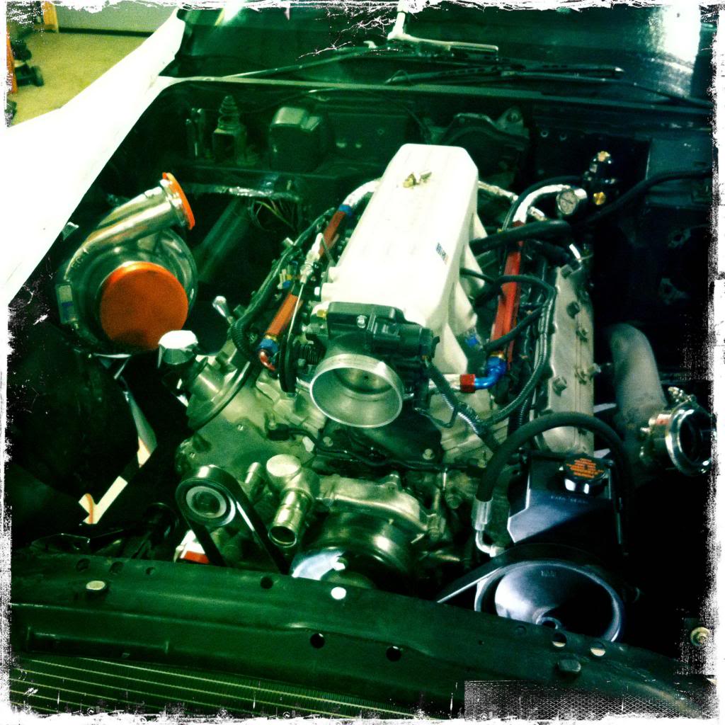
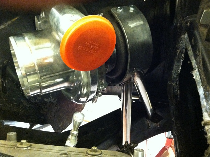
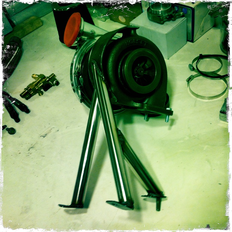
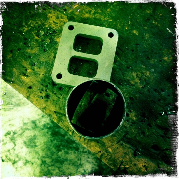
Mounted the turbo in the location of the factory AC/Heater unit, I am obviously running neither. I made a bracket that wraps around the turbo and bolts onto tabs I have made on the frame. driver side manifold is flipped forward and passenger side is in the normal position.
a couple images of the turbo mount
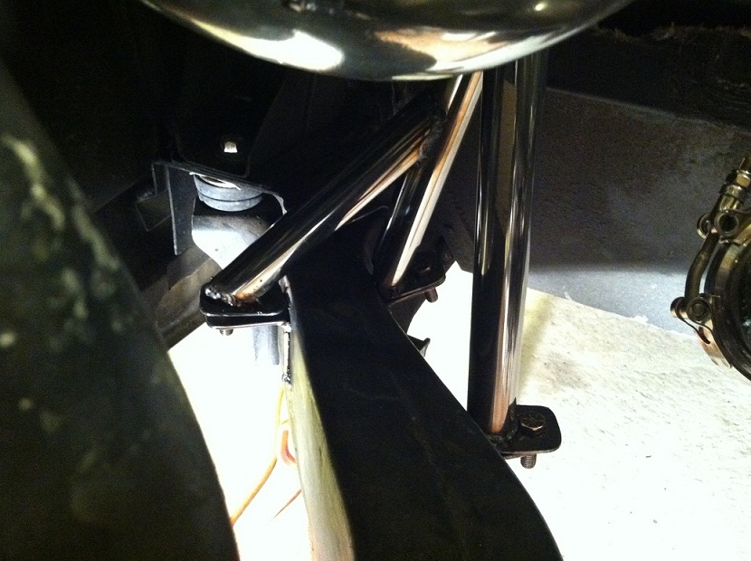
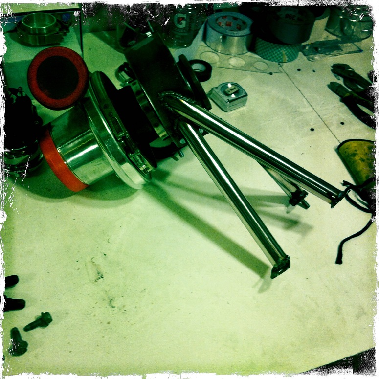
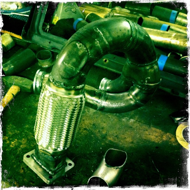
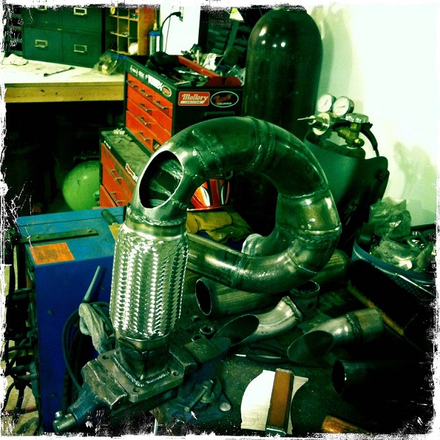
The cross over setup
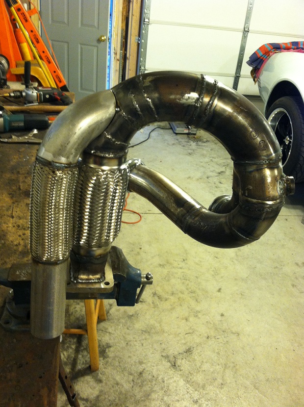
and all welded up
a couple images of the turbo mount
The cross over setup
and all welded up
Last edited by User-C3; 10-24-2012 at 02:38 PM.
 10-24-2012, 02:34 PM
#22
Instructor
Thread Starter
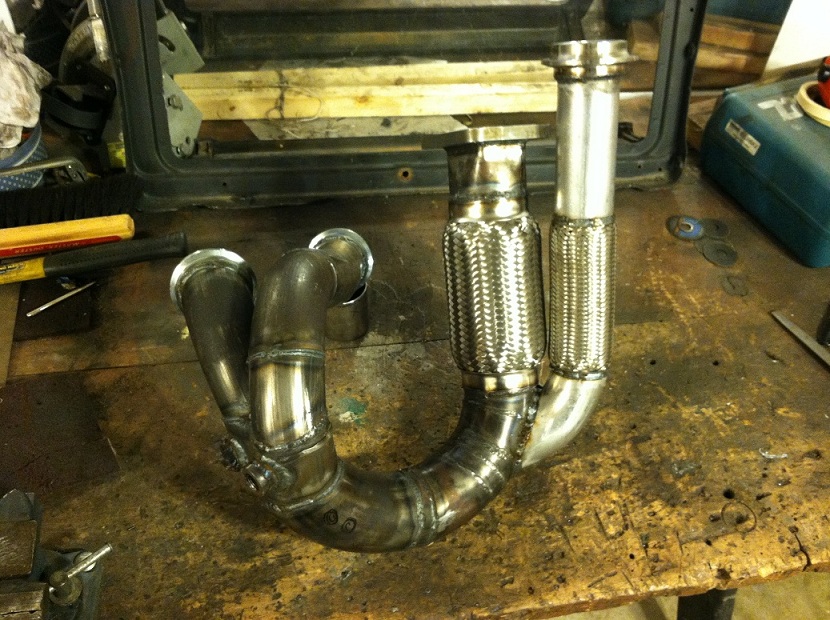
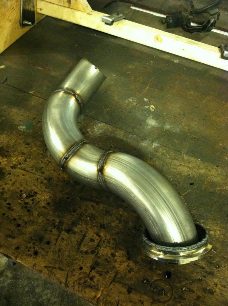
The merge pipe was pretty tricky, I am running a 2.5" cross over into a single 3" feeding the turbo with a 3" flexpipe. The merg aslo has to wrap around the bottom of the frame and come up into the turbo and to do this I had make a series of cuts in the 3" tubing to make the bend a bit tighter. The clearance tolerance in this area is really tight to say the least.
The wastegate had an original position planned but quickly found out it wsa not going to work out. The second choice ended up being the best way to go and the most optimal for flow. I also needed another flexpipe for the waste gate tubing based on the location and luckly had one lying around the garage that I found on the street some months ago.
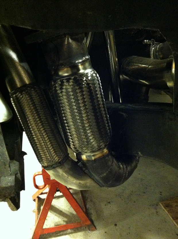
Here is a good shot of the way it wraps the frame rail. I had to cut out part of the inner fender to allow for the merg to be put in and taken out. I will make a sheet metal removable panel to replace the removed fiberglass section.
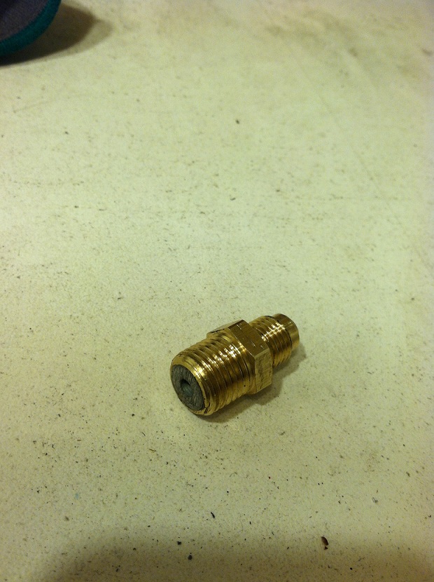
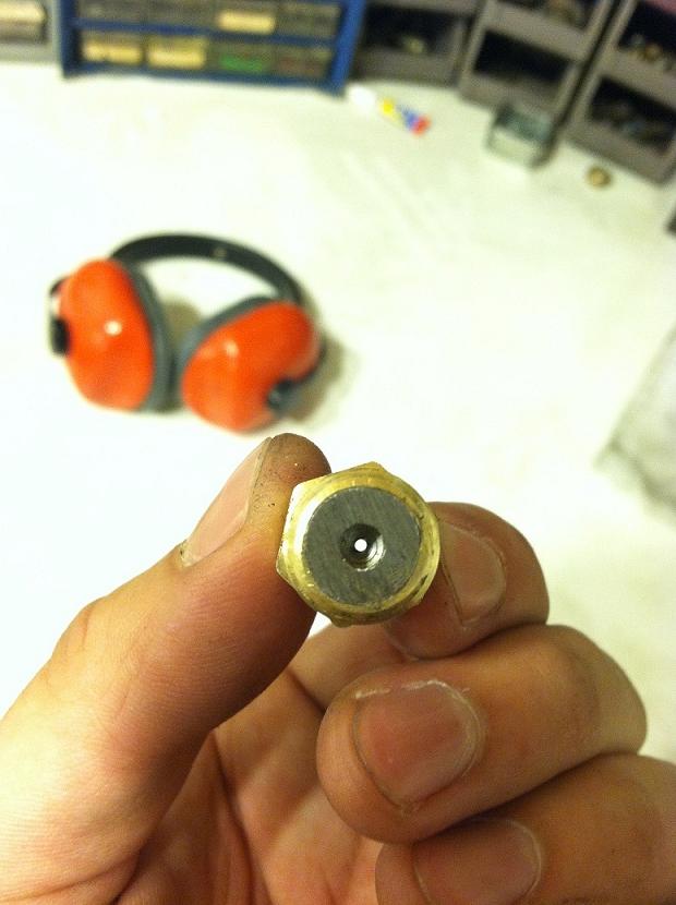
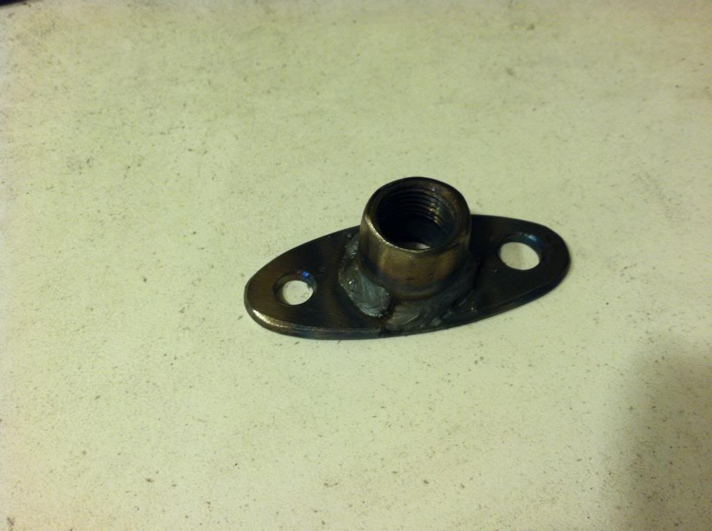
Needed an oil restrictor for the turbo oil feed line. I noticed the turbo had a fitting on it, which can be seen in some of the earlier photos. It was in a sense a reducer of sorts, and I didnt need it there, but it didnt fit in the oil feed port. I got a brass fitting that fit the feed port, and my feed line. Tapped the inside of the brass fitting and screwed in the reducer with a bunch of locktite. Once in there I took my cut off wheel and cut off the other end of the fitting creating a perfect restrictor.
The wastegate had an original position planned but quickly found out it wsa not going to work out. The second choice ended up being the best way to go and the most optimal for flow. I also needed another flexpipe for the waste gate tubing based on the location and luckly had one lying around the garage that I found on the street some months ago.
Here is a good shot of the way it wraps the frame rail. I had to cut out part of the inner fender to allow for the merg to be put in and taken out. I will make a sheet metal removable panel to replace the removed fiberglass section.
Needed an oil restrictor for the turbo oil feed line. I noticed the turbo had a fitting on it, which can be seen in some of the earlier photos. It was in a sense a reducer of sorts, and I didnt need it there, but it didnt fit in the oil feed port. I got a brass fitting that fit the feed port, and my feed line. Tapped the inside of the brass fitting and screwed in the reducer with a bunch of locktite. Once in there I took my cut off wheel and cut off the other end of the fitting creating a perfect restrictor.
10-24-2012, 03:29 PM
#23
Instructor
Thread Starter
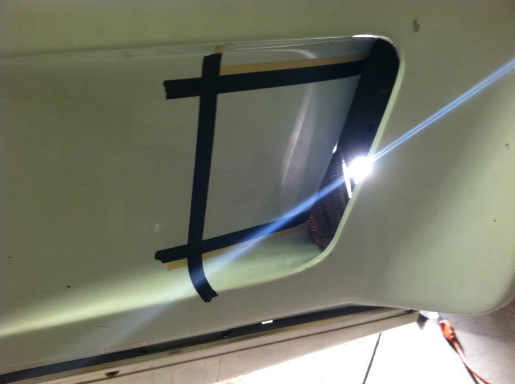
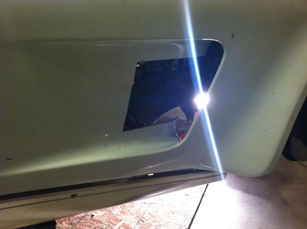
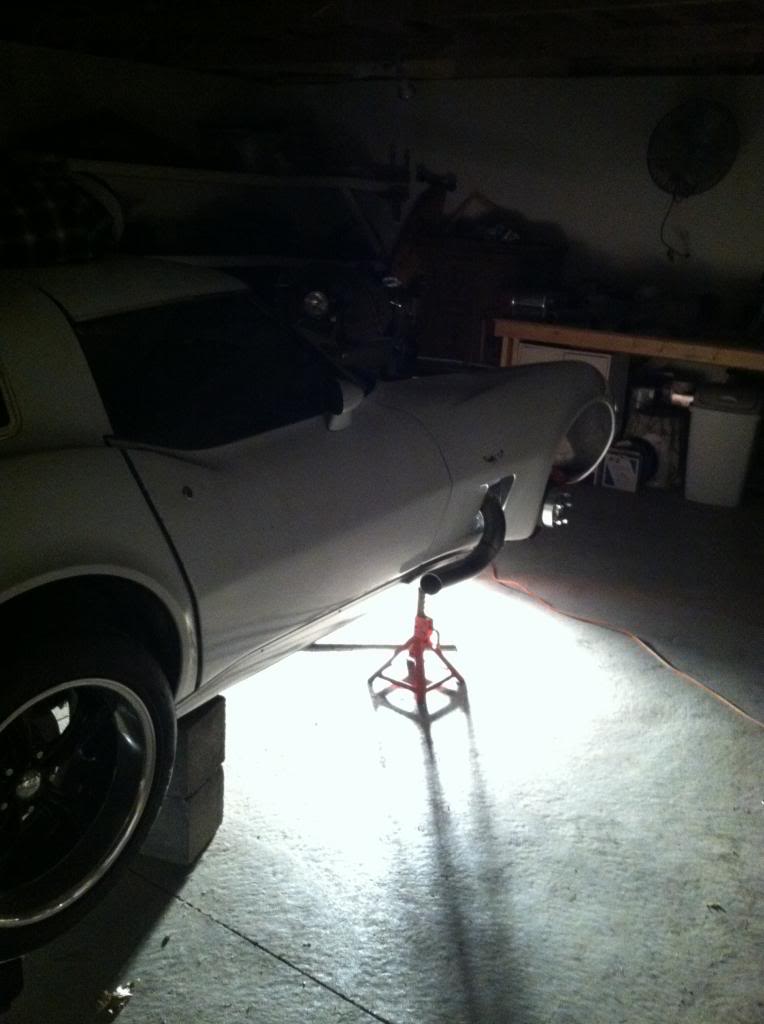
Ive had the idea for a single shorty style side pipe coming through the fender vent for quite some time. This leads up to the last couple days of work, and where it stand right now. I started by masking off the area I wanted to cut. I will making a sheet metal piece to fill the gaps and creat a nice asthetic around the tubing and help with some heat protection.
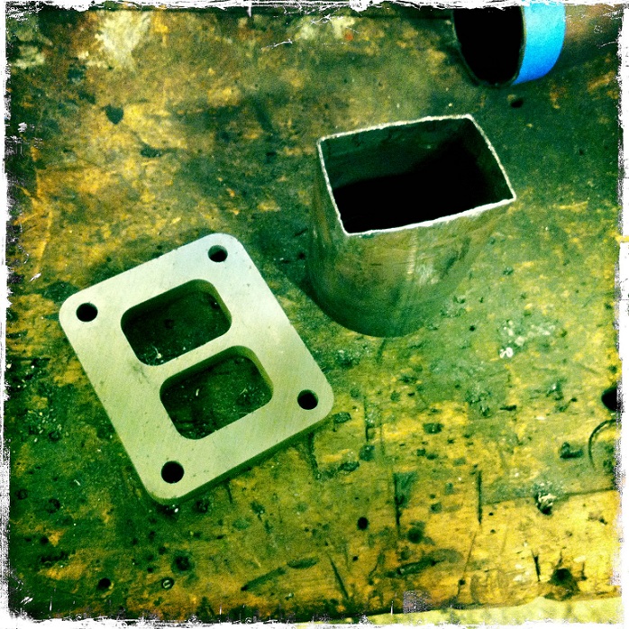
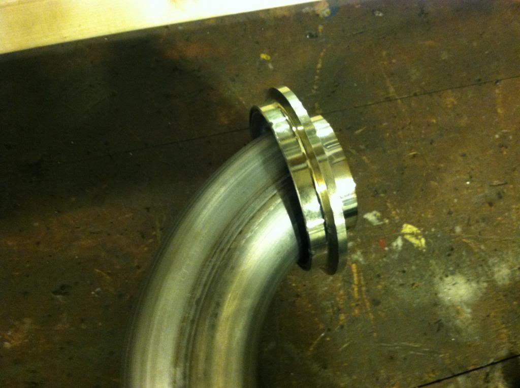
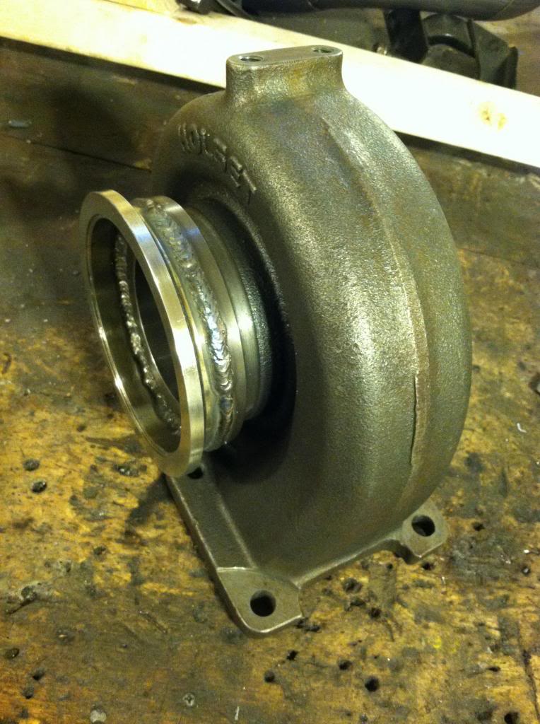
This is v-band for the down pipe/side pipe off the turbo. I am welding on a 4" V-band but running a 3" tubing, the clearance is so tight I had to run a reducer inside the v-band clamp thats buts up against the turbo housing where the outlet is. It's the perfect size for the outlet, but I wanted the ability to upgrade the exhaust size later if desired.
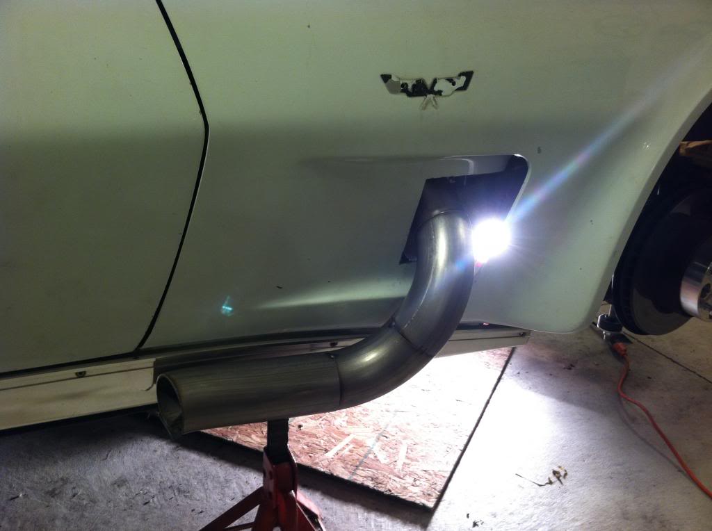
And how it sits right now
This is v-band for the down pipe/side pipe off the turbo. I am welding on a 4" V-band but running a 3" tubing, the clearance is so tight I had to run a reducer inside the v-band clamp thats buts up against the turbo housing where the outlet is. It's the perfect size for the outlet, but I wanted the ability to upgrade the exhaust size later if desired.
And how it sits right now
10-29-2012, 02:53 PM
#24
Instructor
Thread Starter
I orderd a bunch of heat wrap to wrap the manifolds, and all the other hot side piping. I also ordered an OBX resonator. That will be the "muffler of sorts to go on the sidepipe, should look pretty good, and sound good as well.
Made an oil return bung for the turbo. I'm a fan of the make it before you buy it.
Did some finishing welds on the V-band and down pipe for the sidepipe. I also started smoothing it out to polish it, but I think I may just wrap it to the resonator.
Welded the 4" V-band flange to the turbo housing. Welded both outside and inside.
10-29-2012, 03:19 PM
#25

This is a great build! 
10-29-2012, 04:41 PM
#27
 10-29-2012, 08:55 PM
#28
Safety Car

Member Since: Aug 2001
Location: North Easton Mass
Posts: 4,883
Likes: 0
Received 8 Likes
on
8 Posts

Looking really good! I admire your fabrication skills. I could use you for a next-door neighbor!
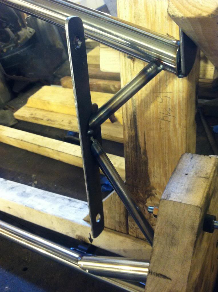
I do have one question regarding the shoulder harness mount. Do you think the tubing is going to be strong enough in the unfortunate event of a crash? The lower bar is braced pretty parallel to the bar but it looks to me like the upper bar would bend forward under load. The braces for the upper bar are at an angle so I don't think they would offer much support. Most 5-point harnesses that I've seen are mounted to a roll cage that is welded to the frame.
Rick B.
10-30-2012, 07:59 AM
#29
Instructor
Thread Starter
10-30-2012, 08:12 AM
#30
Instructor
Thread Starter
Looking really good! I admire your fabrication skills. I could use you for a next-door neighbor!
I do have one question regarding the shoulder harness mount. Do you think the tubing is going to be strong enough in the unfortunate event of a crash? The lower bar is braced pretty parallel to the bar but it looks to me like the upper bar would bend forward under load. The braces for the upper bar are at an angle so I don't think they would offer much support. Most 5-point harnesses that I've seen are mounted to a roll cage that is welded to the frame.
Rick B.
11-01-2012, 08:50 AM
#31
Instructor
Thread Starter
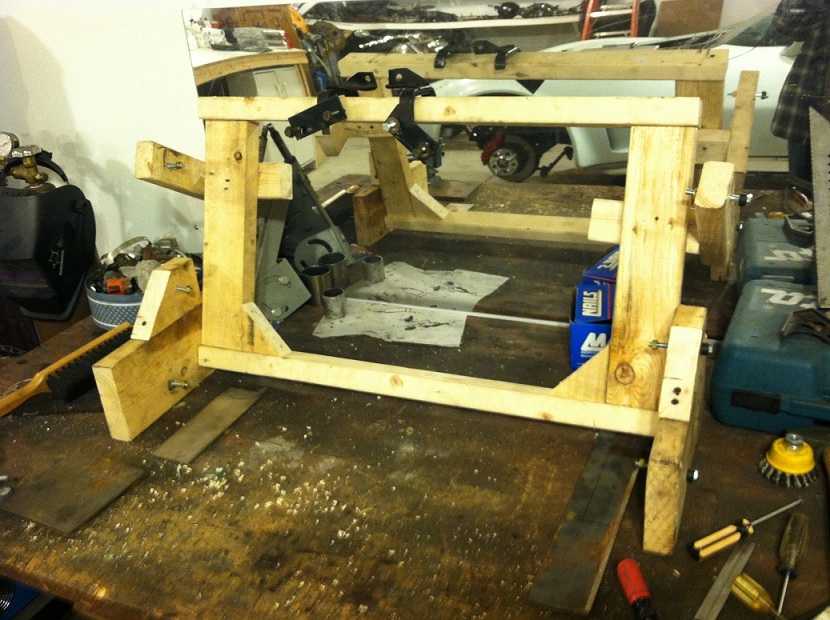
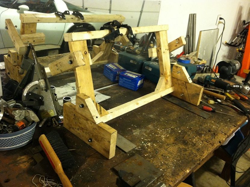
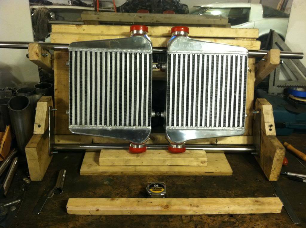
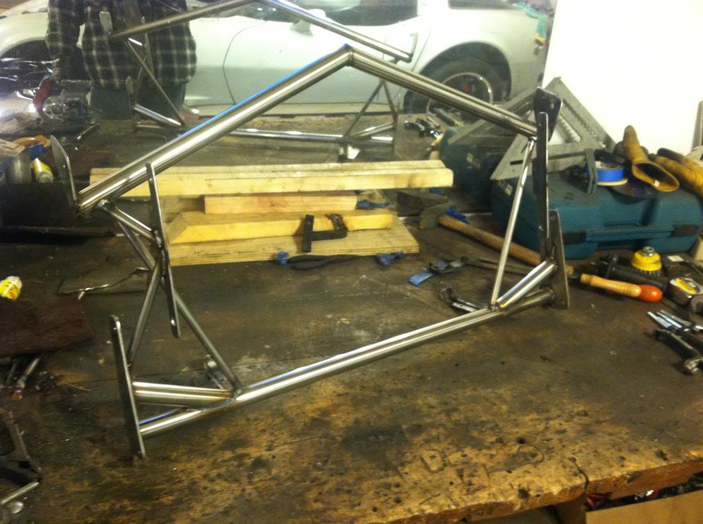
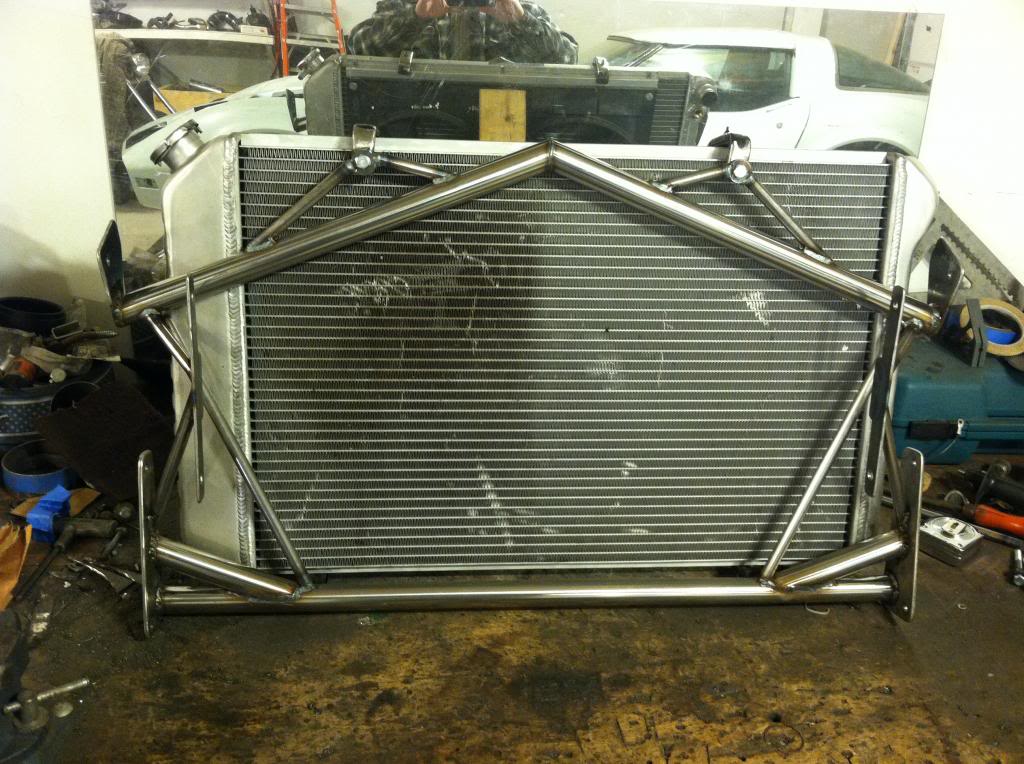
I've never really liked the look of the radiator surround. My intercooler setup will be infront of the radiator and will put the intake tubes coming straight over the top of the rad. Knowing this the suround would have to be altered to give clearance for the tubes, and also for mounting of the intercoolers. So I decided to make a new one that took care of all my needs. I started by using the factory setup as a template and made this crude wood jig. Its a bit janky but its doing the job. So far I have the side plates made for mounting, the bottom rad supports and bottom bar tacked in place. Working out now how the intercooler is going to be located.
11-08-2012, 03:48 PM
#32
Instructor
Thread Starter
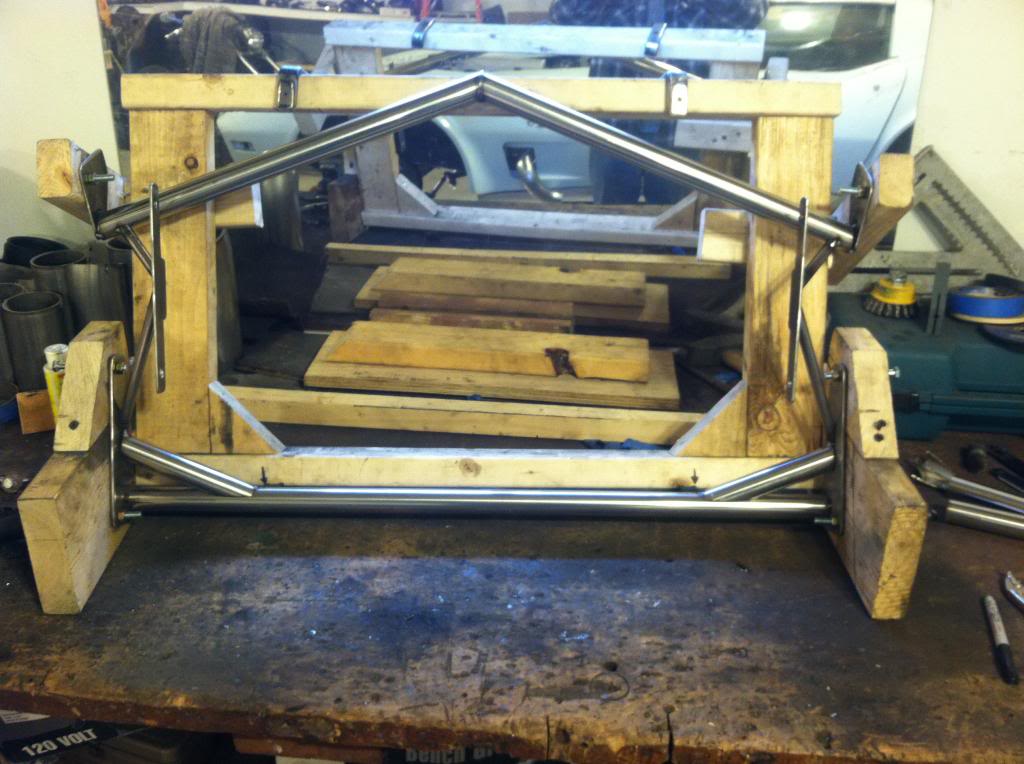
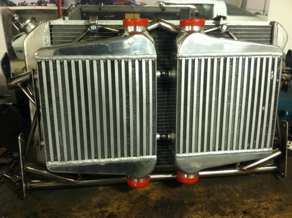
Made some progress lately. Pretty much wraped up the radiator/ intercooler mount. I'm very pleased with it, just need to paint the unpolished rods and mount plates.
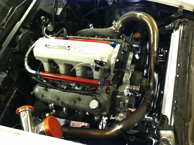
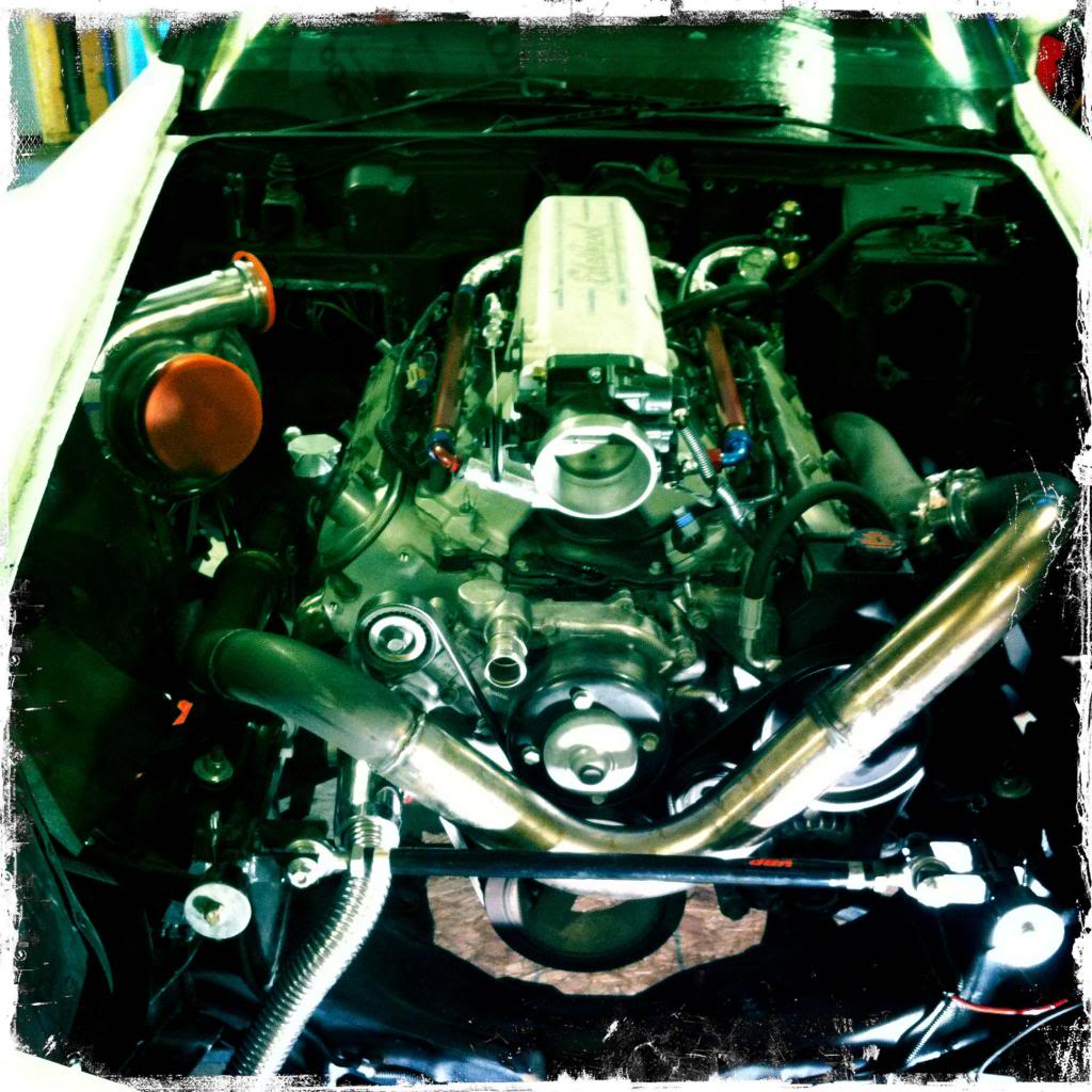
got all the hotside piping heat wrapped. Everything is now connected and waiting for some finalized minor things to fire it up and hear the turbo. Cant wait...
I also changed up the brake booster which you can see in this photo. I couldnt run the stock booster because it was hitting the manifold after I flipped it to go up and forward. I picked up a 7" dual diaphragm chrome unit, cleaned up and painted my master and got it all bolted up. Fits great, and looks even better, I will be interested to see how it feels once up and running.
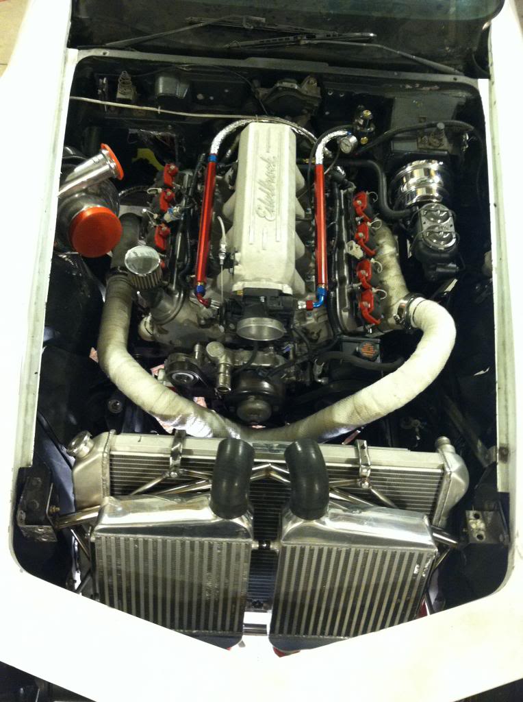
Last edited by User-C3; 11-08-2012 at 03:54 PM.
11-08-2012, 06:03 PM
#33
Drifting

Wow that is looking very impressive, I kind of wish I went that route with my LSX build, I guess I could start over and go this route. ???
Your work is fantastic along with your skills, keep up the good work. I'm looking forward to your progress reports.
Riggs
Your work is fantastic along with your skills, keep up the good work. I'm looking forward to your progress reports.
Riggs
11-08-2012, 07:55 PM
#34
Le Mans Master


Member Since: Jan 2007
Location: Danville Illinois
Posts: 9,292
Received 570 Likes
on
286 Posts
Finalist 2021 C3 of the Year - Modified
C3 of Year Finalist (appearance mods) 2019

Nice fab skills, great project.

Also wish you where my neighbor, my welding skills are not very good.
Also wish you where my neighbor, my welding skills are not very good.
11-09-2012, 08:38 AM
#35
Instructor
Thread Starter
Wow that is looking very impressive, I kind of wish I went that route with my LSX build, I guess I could start over and go this route. ???
Your work is fantastic along with your skills, keep up the good work. I'm looking forward to your progress reports.
Riggs
Your work is fantastic along with your skills, keep up the good work. I'm looking forward to your progress reports.
Riggs
Nice fab skills, great project.
Also wish you where my neighbor, my welding skills are not very good.
Also wish you where my neighbor, my welding skills are not very good.
11-09-2012, 02:18 PM
#36
Nice job on the radiator support! I fabricated one too and can appreciate the work it takes.
11-10-2012, 04:14 PM
#37
Instructor
Very cool build. I agree with the awesome fabrication skills. I like the exhaust exiting through the vents. It reminds me of Bill Mitchell's Stingray Racer.
Chappie
Chappie
11-11-2012, 10:30 PM
#38
Intermediate

Member Since: Nov 2012
Location: Chino CA
Posts: 45
Likes: 0
Received 0 Likes
on
0 Posts

very interesting, I was thinking about building a c3 for drifting. How is the car compared to any other cars you've drifted?
Last edited by battery1882; 11-11-2012 at 11:08 PM.
11-15-2012, 11:59 AM
#39
Instructor
Thread Starter
Nice job on the radiator support! I fabricated one too and can appreciate the work it takes.
Very cool build. I agree with the awesome fabrication skills. I like the exhaust exiting through the vents. It reminds me of Bill Mitchell's Stingray Racer.
Chappie
Chappie
very interesting, I was thinking about building a c3 for drifting. How is the car compared to any other cars you've drifted?
I say go for it, I have seen older muscle cars setup for drifting, and to be honest its just pure bad ***. The corvette isnt too terribly heavy either. people are drifting modern GTO's and those things weigh a ton.
11-15-2012, 12:21 PM
#40
Instructor
Thread Starter
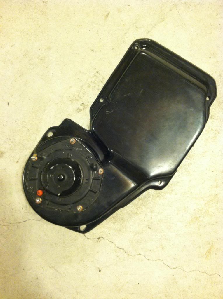
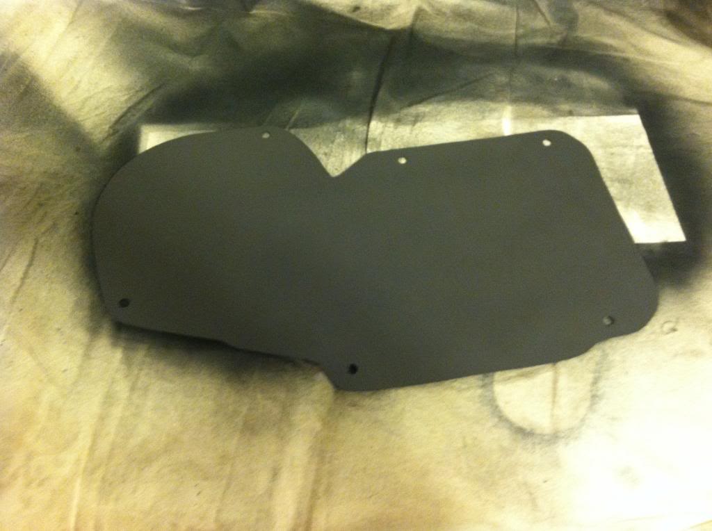
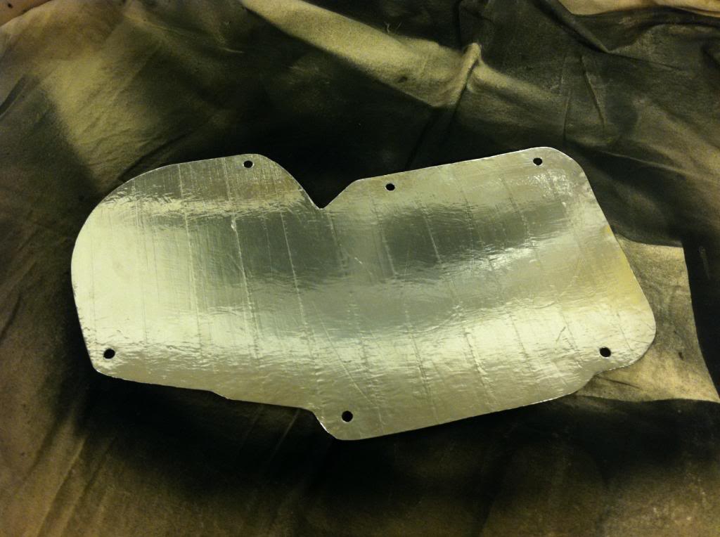
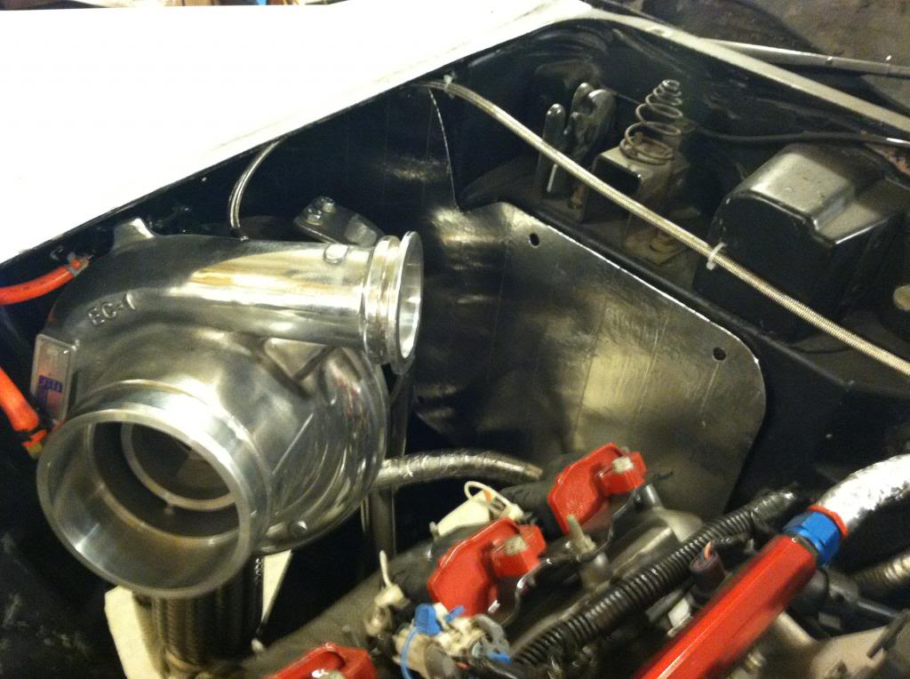
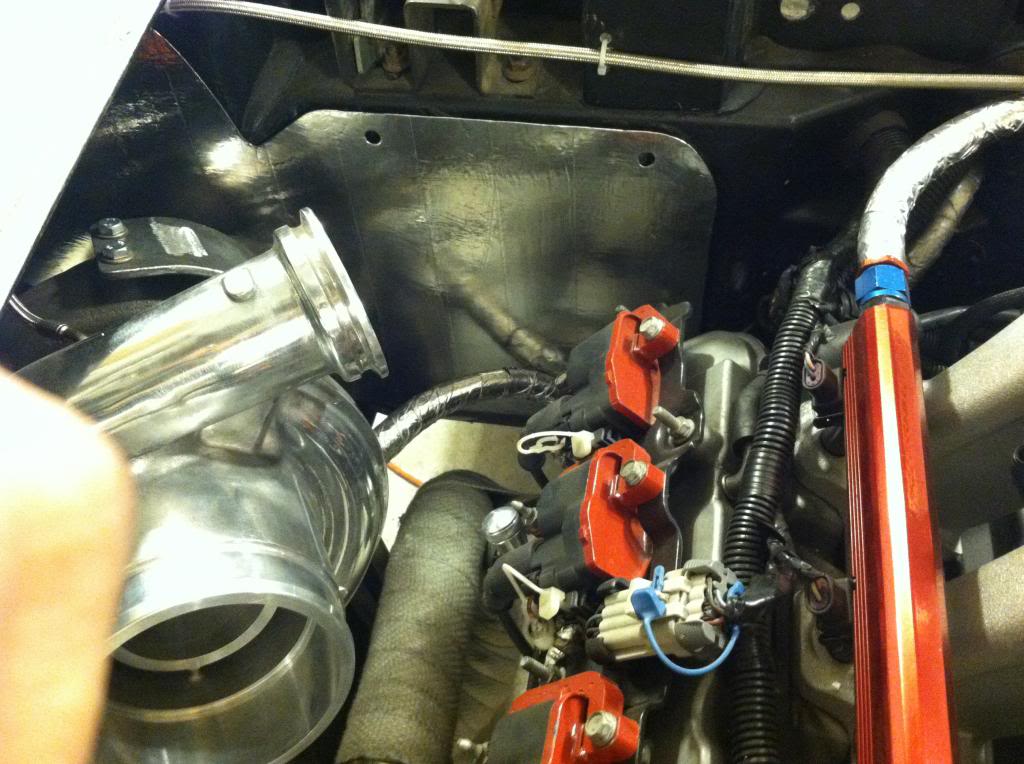
Previously I was using the A/C delete panel but it didnt allow enough room for the turbo so I cut a new sheet metal panel out.
Painted the engine bay side with high temp paint, and the interior side with bed liner.
I then covered the engine bay side with some aluminum tape to act as a bit of a heat diflector
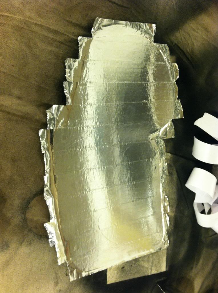
I am pleased with the outcome, looks pretty clean
Painted the engine bay side with high temp paint, and the interior side with bed liner.
I then covered the engine bay side with some aluminum tape to act as a bit of a heat diflector
I am pleased with the outcome, looks pretty clean