
Front inner wheel bearing fit-pics
 01-21-2012, 06:51 PM
#21
Burning Brakes


Thread Starter

The hub needs to be replaced. I think your spindle is fine. That inner bearing does not need to be tight against the face of the spindle but the race has to be a pressed fit into the hub. I usually use the old race and a hammer to carefully install the new race. You want it to go in straight.
You drill the rivets out holding the rotor to hub, buy a new hub (may come with races and bearings) if not replace inner and outer race. Pack the bearings and install them into the races then carefully tap the inner seal in. Install Hub onto spindle and install washer and castle nut and snug it. Spin the hub to seat the bearings then just snug the castle nut until you feel a slight drag spinning the hub. Back off castle nut to the next slot and install the cotter pin. replace rotor onto new hub securing it with a couple wheel lugs and check rotor runout with magnetic base dial indicator. Shim rotor to hub to achieve .002 runout or less. Sometimes you can pull the rotor off the studs and rotate it a hole then check runout. Do this until you find the spot that is closest to 0 runout then shim to spec. Then replace the caliper and pads, install the tire and torque the lugs. No need to replace rivets holding the rotor to hub. I would check the other side before you buy parts but it is likely fine.
You drill the rivets out holding the rotor to hub, buy a new hub (may come with races and bearings) if not replace inner and outer race. Pack the bearings and install them into the races then carefully tap the inner seal in. Install Hub onto spindle and install washer and castle nut and snug it. Spin the hub to seat the bearings then just snug the castle nut until you feel a slight drag spinning the hub. Back off castle nut to the next slot and install the cotter pin. replace rotor onto new hub securing it with a couple wheel lugs and check rotor runout with magnetic base dial indicator. Shim rotor to hub to achieve .002 runout or less. Sometimes you can pull the rotor off the studs and rotate it a hole then check runout. Do this until you find the spot that is closest to 0 runout then shim to spec. Then replace the caliper and pads, install the tire and torque the lugs. No need to replace rivets holding the rotor to hub. I would check the other side before you buy parts but it is likely fine.

Lastly, is the wheel hub unique to Corvettes or can a period correct substitute from another GM car work as a replacement?

 01-21-2012, 07:46 PM
#22
Race Director


I am sure the front hub is 1969-1982 covette only. Here is a good description on adjusting rotor runout. It is for rear brakes but the front is the same idea.
http://www.corvette-restoration.com/...e_calipers.htm
Some use cans cut for shims, aluminum foil, shim stock or the shims are sold at corvette parts houses. I guess the spec is .005 but I always go .002 since your there anyway. The 4 piston calipers require a true runout. They are machined as a unit after riveting to the front hubs and rear axles at the factory so once the rivets are drilled out and the rotor or hub replaced they need to be shimmed to spec.
01-21-2012, 07:54 PM
#23
Drifting

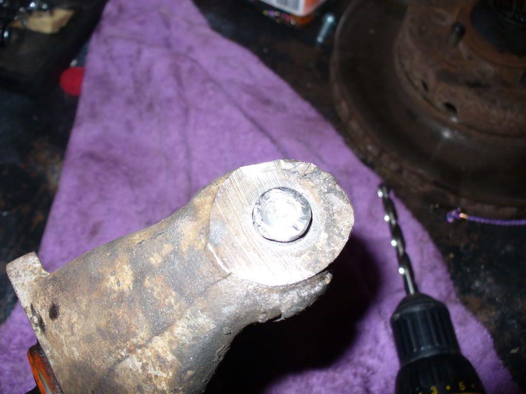
Mako is correct. 69-82 Corvette only. I always machine the face of the hub for zero runout. If you look closely at the hub face you will see 4 dents and 4 raised metal areas around each of the studs. This is caused by the machine that originally installed the studs.
Mike
Mike
02-03-2012, 11:45 PM
#24
Burning Brakes
Thread Starter
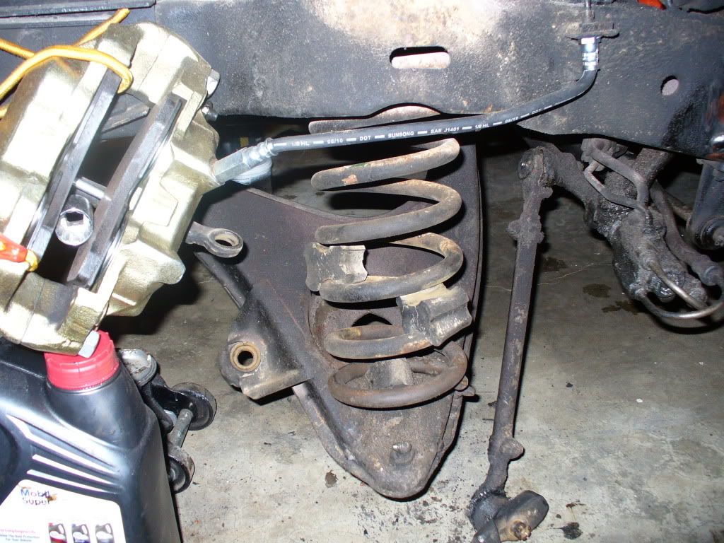
Moving at the speed of a glacier I am estimating about 10% done with : replacing upper and lower bjs, front coil springs, shocks, new hub,(ordered with new rotor) 2 wheel bearings, sway bar links, and bought a couple of shims. $450. The frozen lower bj is taking awhile-- first cut with air tool, now down to carefully drilling out.
thanks for the help everyone.
thanks for the help everyone.
02-04-2012, 04:38 AM
#25
Drifting

That is a lot of work. It will be interesting to see what the front ride height ends up at with the new springs.
The old springs were obviously pretty worn out since someone added the rubber spacers to get a little more life out of them. Keep the pictures coming!
The old springs were obviously pretty worn out since someone added the rubber spacers to get a little more life out of them. Keep the pictures coming!
02-04-2012, 02:44 PM
#26
Burning Brakes
Thread Starter
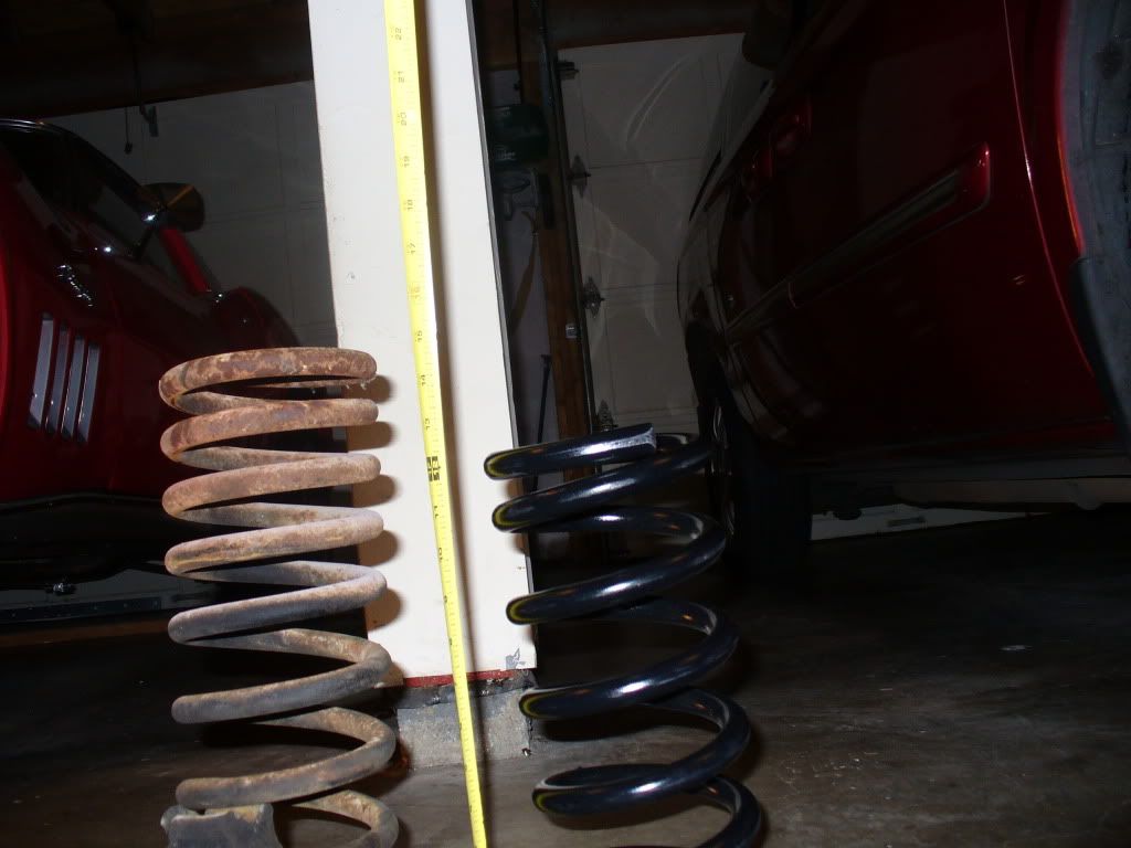
hmmm... the old or existing springs are longer than the ones shipped for replacement. Digging into the the original height question, I walked away with an answer that the free standing height should be a skosh over 13 inches. The spring coming out with all the spacers is about 15" Yes, it will be interesting when it all gets back together.
02-04-2012, 02:53 PM
#27
Racer

hmmm... the old or existing springs are longer than the ones shipped for replacement. Digging into the the original height question, I walked away with an answer that the free standing height should be a skosh over 13 inches. The spring coming out with all the spacers is about 15" Yes, it will be interesting when it all gets back together.
02-04-2012, 10:52 PM
#29
Burning Brakes
Thread Starter
 02-04-2012, 11:21 PM
#30
Drifting
The difference in height is nothing to worry about. The original springs are variable rate. The new springs are constant rate. I'm assuming those are Moog springs.
Mike
Mike
02-23-2012, 11:59 PM
#31
Burning Brakes
Thread Starter
The inside face of the inner bearing race should fit up against the flat behind the spindle. In other words, drive the bearing inner race completely onto the spindle. If it won't go all the way, there is some kind of interference or machining problem on the spindle [very unlikely that the bearing race is mis-machined...although it is possible].
Then install rotor and set castle nut per procedure.
If you have to grind down the fillet radius on the spindle, be careful not to take more metal than you need. Also, make sure you smooth and blend the surface when you get the metal removed; you don't want to create a stress riser that can initiate a crack at the base of the spindle.
02-24-2012, 07:54 AM
#32
Le Mans Master

Do NOT grind down the spindle. I can't believe anyone even suggested this.
 02-24-2012, 10:27 AM
#34
Drifting
Mike
02-24-2012, 11:19 AM
#35
Team Owner

Die grinder with small radius tip. Remove enough metal to get the inner bearing radius to clear (non-interference), then use a fine grinding tip to smooth the surface where you were ginding. Use finer paper to remove and light gouges or tool marks.
Replace the part if you want. The radius is there only as a 'clearance cut' for the bearing radius. You still want it to have a radius there...just smaller, so that it clears any interference with the bearing. This isn't a "big deal" like some others are indicating. But, do what you want.
Replace the part if you want. The radius is there only as a 'clearance cut' for the bearing radius. You still want it to have a radius there...just smaller, so that it clears any interference with the bearing. This isn't a "big deal" like some others are indicating. But, do what you want.
02-24-2012, 11:24 AM
#36
Le Mans Master
Die grinder with small radius tip. Remove enough metal to get the inner bearing radius to clear (non-interference), then use a fine grinding tip to smooth the surface where you were ginding. Use finer paper to remove and light gouges or tool marks.
Replace the part if you want. The radius is there only as a 'clearance cut' for the bearing radius. You still want it to have a radius there...just smaller, so that it clears any interference with the bearing. This isn't a "big deal" like some others are indicating. But, do what you want.
Replace the part if you want. The radius is there only as a 'clearance cut' for the bearing radius. You still want it to have a radius there...just smaller, so that it clears any interference with the bearing. This isn't a "big deal" like some others are indicating. But, do what you want.
You have no idea what you're talking about here. If the radius on the bearing is interfering, it's because it's the wrong bearing.
02-24-2012, 11:36 AM
#37
Burning Brakes
If the radius on the bearing is interfering, it's because it's the wrong bearing.
This may be true, or the radius on the spindle is a little too big. As was stated in post #17, it looks like the bearing fit was ok. If it's not ok now, then I would buy another bearing and see if it works. If a second bearing (different brand) still doesn't fit properly, then I would conclude that the spindle is a little oversize and should be modified or replaced. Another thing I would do is try to determine exactly what is stopping the bearing from going on all the way. Try painting the spindle with a sharpie pen or use some machinist Dykem. Then install the bearing and try to rotate the inner race to rub off the Dykem and show where the interference is.
Personally, I would strongly resist grinding on the spindle, but it may only need a little bit. If you decide you have to go this way, protect the straight diameter with some tape so you don't make it undersize.
John
Last edited by JohnRR; 02-24-2012 at 11:37 AM. Reason: mis spelling
02-24-2012, 05:52 PM
#39
Burning Brakes
Thread Starter
If the radius on the bearing is interfering, it's because it's the wrong bearing.
This may be true, or the radius on the spindle is a little too big. As was stated in post #17, it looks like the bearing fit was ok. If it's not ok now, then I would buy another bearing and see if it works. If a second bearing (different brand) still doesn't fit properly, then I would conclude that the spindle is a little oversize and should be modified or replaced. Another thing I would do is try to determine exactly what is stopping the bearing from going on all the way. Try painting the spindle with a sharpie pen or use some machinist Dykem. Then install the bearing and try to rotate the inner race to rub off the Dykem and show where the interference is.
Personally, I would strongly resist grinding on the spindle, but it may only need a little bit. If you decide you have to go this way, protect the straight diameter with some tape so you don't make it undersize.
John
This may be true, or the radius on the spindle is a little too big. As was stated in post #17, it looks like the bearing fit was ok. If it's not ok now, then I would buy another bearing and see if it works. If a second bearing (different brand) still doesn't fit properly, then I would conclude that the spindle is a little oversize and should be modified or replaced. Another thing I would do is try to determine exactly what is stopping the bearing from going on all the way. Try painting the spindle with a sharpie pen or use some machinist Dykem. Then install the bearing and try to rotate the inner race to rub off the Dykem and show where the interference is.
Personally, I would strongly resist grinding on the spindle, but it may only need a little bit. If you decide you have to go this way, protect the straight diameter with some tape so you don't make it undersize.
John
02-24-2012, 08:36 PM
#40
Burning Brakes
If the bearing gets stuck 1/4" away from the shoulder then it sounds to me like it's not an oversize radius. Closely inspect the straight diameter near the radius for damage like a hit from a hammer or a punch from a previous owner. If you have access to a micrometer then take diameter measurements to see if the straight diameter is actually straight. Perhaps this spindle is defective(tapered) and the bearings never really seated properly. You just may be the first one to discover it.
John
John