
driveshaft angle
 01-02-2014, 02:55 PM
#1
Safety Car


Thread Starter
Member Since: May 2004
Location: los altos hills california
Posts: 3,605
Received 1,125 Likes
on
729 Posts

Been chasing a vibration under load. The LS conversion has the motor sitting a little higher and I am wondering what acceptable ranges for the transmission and differential angles relative to the driveshaft are?
It is a bit hard to measure really accurately but my digital angle gauge suggests about 2.7 degrees for the tranny to the driveshaft and about 2.2 degrees for the driveshaft to the differential. These angles are in the horizontal plane. That would make sense for the motor sitting up higher.
The vertical plane angles are pretty much stock. I don't see that anything has necessarily been relocated from the stock position.
The transmission yoke and tailshaft were renewed sometime back and I think that should still be pretty tight. All the universals including the half shafts have been replaced and everything balanced by South Bay Driveline. The half shafts are in a pretty much horizontal position when the car is on the ground.
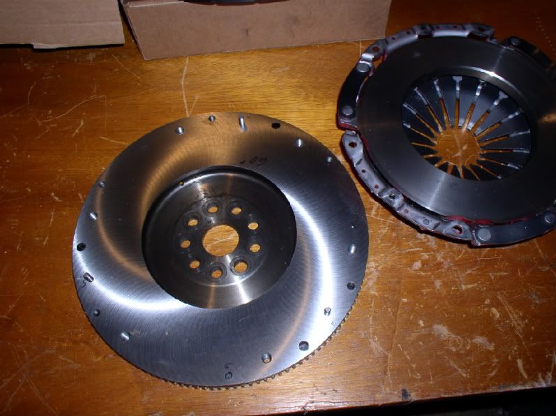
Pulled the clutch and flywheel out and had them balanced. There is some vibration still when I rev the motor in neutral so that may be a forcing function to any other problems. That's another story*.
It wouldn't be too hard to put a spacer under the transmission. I am thinking that those two angles ought to be a bit closer to each other.
I've found a number of threads that suggest just how hard these things are to pin down, but in the interest of one thing at a time, what should the drive line angles be? And should the two angles be about the same?
___________________________
*I reused my SBC pressure plate to mount to the LS flywheel but the mounting holes were a bit too small. Reamed them out very carefully but it is possible I introduced a tiny amount of eccentricity. I don't want to buy another pressure plate and do this job again until I work the easier stuff!
It is a bit hard to measure really accurately but my digital angle gauge suggests about 2.7 degrees for the tranny to the driveshaft and about 2.2 degrees for the driveshaft to the differential. These angles are in the horizontal plane. That would make sense for the motor sitting up higher.
The vertical plane angles are pretty much stock. I don't see that anything has necessarily been relocated from the stock position.
The transmission yoke and tailshaft were renewed sometime back and I think that should still be pretty tight. All the universals including the half shafts have been replaced and everything balanced by South Bay Driveline. The half shafts are in a pretty much horizontal position when the car is on the ground.
Pulled the clutch and flywheel out and had them balanced. There is some vibration still when I rev the motor in neutral so that may be a forcing function to any other problems. That's another story*.
It wouldn't be too hard to put a spacer under the transmission. I am thinking that those two angles ought to be a bit closer to each other.
I've found a number of threads that suggest just how hard these things are to pin down, but in the interest of one thing at a time, what should the drive line angles be? And should the two angles be about the same?
___________________________
*I reused my SBC pressure plate to mount to the LS flywheel but the mounting holes were a bit too small. Reamed them out very carefully but it is possible I introduced a tiny amount of eccentricity. I don't want to buy another pressure plate and do this job again until I work the easier stuff!
Last edited by ignatz; 01-02-2014 at 03:15 PM. Reason: typo
 01-02-2014, 06:26 PM
#2


OK, first thing, engine down angle absolutely has to match the differential up angle. I had the same issues with my LS Richmond 6 speed swap. The original driveline was close to 0 degrees at the engine, 0 degrees on the driveshaft and 0 degrees at the differential. Putting the LS and Richmond ended up with the engine almost 3 degrees dow. I was able to shim it close to 2 degrees without hitting the tunnel.
Next adjustment is to get the diff pinion angle up 2 degrees in front. I did this by cutting down the front rubber differential mount isolator to bring the front of the diff up. I got it close to 2 degrees. You may have to space the rear mount down too.
After you get the engine down angle to match the diff pinion up angle, the driveshaft simply has to be within 3 degrees of the engine/diff angle.
01-02-2014, 07:50 PM
#3
Safety Car
Thread Starter
Member Since: May 2004
Location: los altos hills california
Posts: 3,605
Received 1,125 Likes
on
729 Posts
Makes sense Gary and thanks. That is way simpler than what I was thinking.
There are some flats on the motor casing that should give me the trans angle pretty accurately. I don't think I can rely on the differential casting for the same measurement. Cannot get my angle gauge up high enough so what I think I have to do is fashion an extender to bolt to the universal that drops down a bit and measure off that. Since I have to do that anyway guess I'll make two extenders, one for each end. If you've got a better way ......
I think I have plenty of tunnel room.
This may be a couple of days before I have results.
01-02-2014, 08:07 PM
#4


ignatz,
HNY to you. If you are getting vibration while revving your motor in neutral, then no amount of angle adjustment is going to help. You have a vibration either in your engine assembly or your pressure plate/clutch combo. My money is on the pressure plate from your description of how you made it fit on the LS flywheel. Best of luck sorting all of this out. Vibrations in the drive line are annoying.

HNY to you. If you are getting vibration while revving your motor in neutral, then no amount of angle adjustment is going to help. You have a vibration either in your engine assembly or your pressure plate/clutch combo. My money is on the pressure plate from your description of how you made it fit on the LS flywheel. Best of luck sorting all of this out. Vibrations in the drive line are annoying.
01-02-2014, 08:40 PM
#5
Safety Car
Thread Starter
Member Since: May 2004
Location: los altos hills california
Posts: 3,605
Received 1,125 Likes
on
729 Posts
Hi Brando: Thanks for checking in. There is a quantitative and qualitative difference in what I feel between the vibration in neutral and the vibration under power. If I am coupling a small amount of vibration input into a largely misaligned drivetrain it may be being amplified. My choice is to put in a shim or do a whole transplant. I'm going with the shim first to see what happens.
 01-02-2014, 09:03 PM
#7
I don't want to move backward on this thread but in the interest of saving you guys from reading a similar thread I had to start in the near future... Exactly how are you measuring your angles? I have read a few threads with what sound like differing techniques. I am hoping to learn now and avoid having to chase the vibration later.
01-02-2014, 09:34 PM
#8
Safety Car
Thread Starter
Member Since: May 2004
Location: los altos hills california
Posts: 3,605
Received 1,125 Likes
on
729 Posts
I've got one of these
plan to bolt a flat piece of steel to the universal and attach this.
universal flat should be roughly perpendicular to the ground. There was another thread around recently where the guy used a laser level which projects a straight line to check alignment in the other plane

plan to bolt a flat piece of steel to the universal and attach this.
universal flat should be roughly perpendicular to the ground. There was another thread around recently where the guy used a laser level which projects a straight line to check alignment in the other plane
01-02-2014, 09:41 PM
#9
Safety Car
Thread Starter
Member Since: May 2004
Location: los altos hills california
Posts: 3,605
Received 1,125 Likes
on
729 Posts
Myko: I like your creative use of tenses, i.e. - "saving you guys from reading a similar thread I had to start in the near future...". Makes me think you might be driving a deLorean.
I will try to remember to take a picture. I think this will be easy
I will try to remember to take a picture. I think this will be easy
01-03-2014, 03:50 AM
#10
LOL, look high tech. I just used one of these:
http://www.harborfreight.com/dial-ga...der-34214.html
You can find engine angle off the output yoke or the front crank pulley.
The differential has to be done on the pinion yoke (diveshaft and caps off). You'll need a mirror for this on a C3 vette.
Driveshaft is anywhere along it that's flat.
Do a search on driveshaft alignment or angles. It's pretty simple. But because in the C3 world of IRS, you wont see much about it here. Much more common with live rear axles but angles arev important in both.
01-03-2014, 09:27 AM
#11
Burning Brakes

Hey guys,
I just went through getting my driveline angles correct after installing a TKO600 and raising the rear by eliminating the top hats and hard mounting the cross member.
Just wanted to remind you that before you take any of these measurements, you should ensure that the weight of the car is supported by the wheels and that the chassis itself is flat and level. That's the only way to ensure that chassis flex does not alter your angles and that zero degrees on your gauge is actually zero degrees in real life.
Best of luck!
01-03-2014, 07:22 PM
#12
Safety Car
Thread Starter
Member Since: May 2004
Location: los altos hills california
Posts: 3,605
Received 1,125 Likes
on
729 Posts
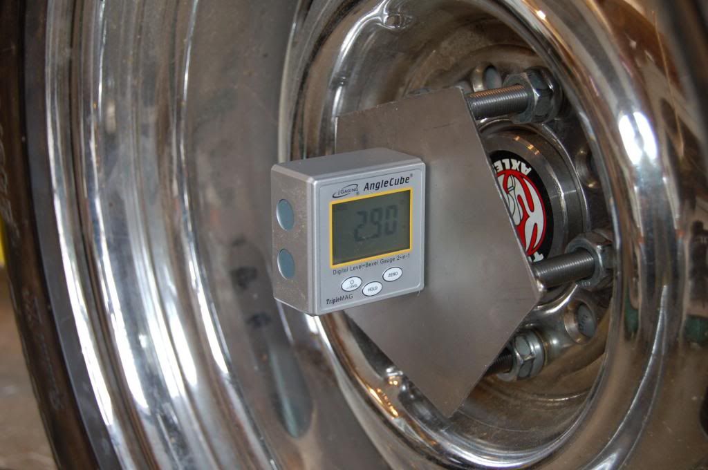
The measurement may be easy but fixing this is another thing. I attached two flat steel plates to the front and back yokes. Here is the tranny end (with the photo rotated 90 degrees).
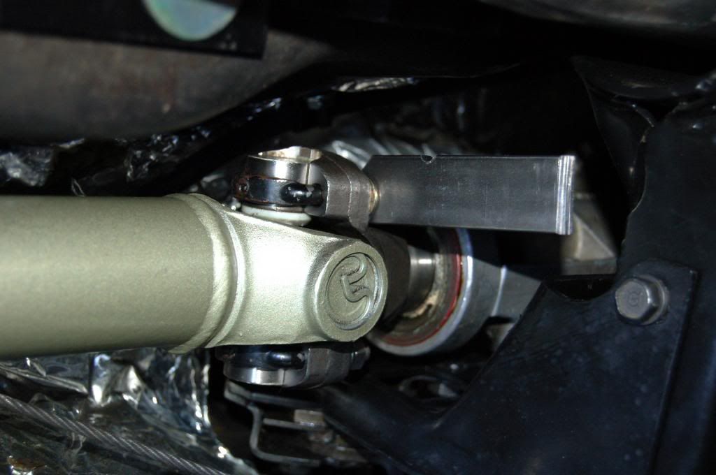
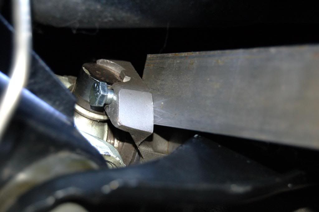
Here is the diff, same deal
You may argue some with the precision but the attachment points are flat machined surfaces. Close enough for a good approximation and I am thinking a lot better than the Harbor Freight gadget.
The angle cube attaches to these plates magnetically like so (ignore the 1.00 reading).
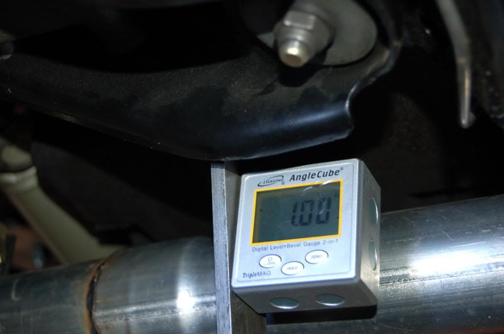
I can zero the angle cube to anything so I chose to zero it to the frame rail. Transferring to the diff gives me a 0.00 reading.
If I move it to the tranny I get 3.5 degrees. The car is on a two post lift, so who knows what the frame sag is. Half a degree? Dunno, but I doubt it is the whole shebang, so let's say I've got 3 degrees as you got Gary.
I guess I am in the same boat as you were. It is roughly 36" from the fronts to the transmission mount. To get a degree is going to take 57.3 degrees/radian divided by 36", or 1.6" of shim (sound right? that is huge).
At the bell housing firewall that's maybe half the way and like you, there ain't no more. So the rest will have to come out of the rear. That looks painful at best. I've got a poly bushing at the frame mount and a rubber bushing sitting on the bench that I can trim some. Certainly don't intend to hard mount it.
I am kind of thinking I want to reslot the diff front mount by welding in some material and redrilling the four holes there. Alternative is to shim the diff to the cross member but I have painful memories of that job.
Can I really twist the differential two degrees? The cross member and spring have to have enough compliance. Spring is fiberglass surrounded by rubber cushions so that is probably OK. Crossmember seems iffy to me.
On the bright side this is probably going to fix my driveline problem.

Here is the diff, same deal

You may argue some with the precision but the attachment points are flat machined surfaces. Close enough for a good approximation and I am thinking a lot better than the Harbor Freight gadget.
The angle cube attaches to these plates magnetically like so (ignore the 1.00 reading).

I can zero the angle cube to anything so I chose to zero it to the frame rail. Transferring to the diff gives me a 0.00 reading.
If I move it to the tranny I get 3.5 degrees. The car is on a two post lift, so who knows what the frame sag is. Half a degree? Dunno, but I doubt it is the whole shebang, so let's say I've got 3 degrees as you got Gary.
I guess I am in the same boat as you were. It is roughly 36" from the fronts to the transmission mount. To get a degree is going to take 57.3 degrees/radian divided by 36", or 1.6" of shim (sound right? that is huge).
At the bell housing firewall that's maybe half the way and like you, there ain't no more. So the rest will have to come out of the rear. That looks painful at best. I've got a poly bushing at the frame mount and a rubber bushing sitting on the bench that I can trim some. Certainly don't intend to hard mount it.
I am kind of thinking I want to reslot the diff front mount by welding in some material and redrilling the four holes there. Alternative is to shim the diff to the cross member but I have painful memories of that job.
Can I really twist the differential two degrees? The cross member and spring have to have enough compliance. Spring is fiberglass surrounded by rubber cushions so that is probably OK. Crossmember seems iffy to me.
On the bright side this is probably going to fix my driveline problem.
01-03-2014, 07:35 PM
#13
Safety Car
Thread Starter
Member Since: May 2004
Location: los altos hills california
Posts: 3,605
Received 1,125 Likes
on
729 Posts
SLVRSHRK: You're saying you raised the aft end of the diff? That makes it point down more. That is exactly the opposite of what I am thinking. Am I looking at something wrong here?
01-04-2014, 12:13 AM
#14
Nam Labrat


Member Since: Sep 2013
Location: New Orleans Loo-z-anna
Posts: 33,892
Received 4,173 Likes
on
2,735 Posts

A slight engine vibration will be magnified by the driveshaft more than you might think---been there.....
and like you said---wrong drivetrain angles will not help the situation.
and like you said---wrong drivetrain angles will not help the situation.
01-04-2014, 04:55 AM
#15
Start over and do this on the wheels. With the rear tires on ramps and jackstands on the frame behind the front wheels, my engine changed 2 degrees.
BTW, over at vettemod, there was someone thatredrilled the diff mount to get the front up a couple degrees.
BTW, over at vettemod, there was someone thatredrilled the diff mount to get the front up a couple degrees.
01-04-2014, 10:33 AM
#16
Burning Brakes
+1 on the frame sag - mine too.
Another thing to think about is there are differences in height between motor mounts. Rubber, Poly, and Steel - especially the poly seem to have brand differences. The slots to the frame horns can also be elongated. It may only give you a slight difference, but then that may help reducing the amount you have to change the differential.
Another thing to think about is there are differences in height between motor mounts. Rubber, Poly, and Steel - especially the poly seem to have brand differences. The slots to the frame horns can also be elongated. It may only give you a slight difference, but then that may help reducing the amount you have to change the differential.
01-04-2014, 11:44 AM
#17
Le Mans Master

Member Since: May 2003
Location: Fernandina Beach FL
Posts: 8,480
Received 3,219 Likes
on
1,731 Posts
2023 Restomod of the Year finalist
2020 C3 of the Year Winner - Modified

I'm w/ Brandon and Doorgunner...
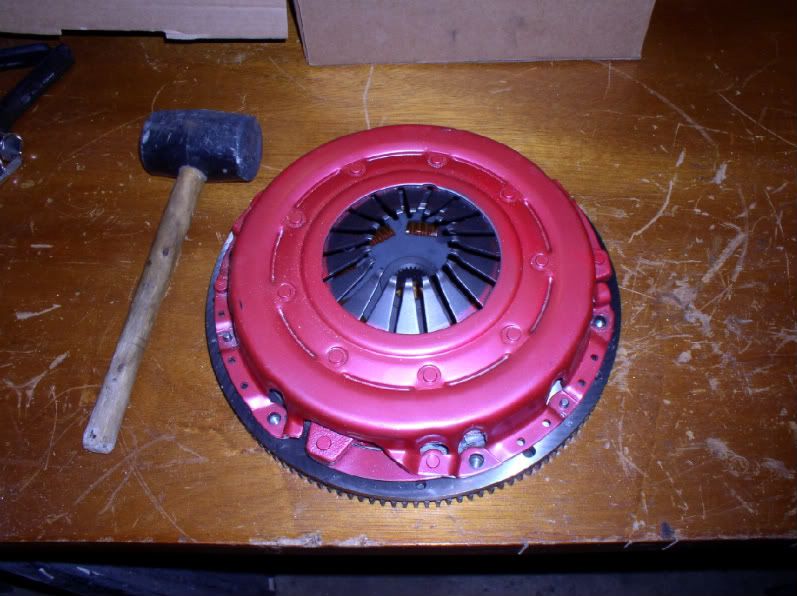
When you say you had the flywheel and PP balanced - Did the shop mark the flywheel and pp so it would be in the same position?
Elongating the holes in the Pressureplate? The shank on the bolts is how the PP is centered-I'm thinking that's the problem.
When I had my Chevy PP fitted to a BMW flywheel, I had three pins drilled, fitted and marked -A-T-M- ( my machinist has a sense of humor)on both the Flywheel and PP so it would always be oriented the same.
Second pic- snug fit- had to tap it in place...
Richard

 01-04-2014, 02:39 PM
#18
Safety Car
Thread Starter
Member Since: May 2004
Location: los altos hills california
Posts: 3,605
Received 1,125 Likes
on
729 Posts
Gary & SLVRSHRK: Put the wheels down on blocks, bounced it up and down a bit and went from 3.5 to 4.0 degrees. Nothing like the 2 degrees you saw Gary. You perhaps have a convertible? I also found the vettemod reference to changing the carrier support, with pictures:
http://www.vettemod.com/forum/showth...?t=3177&page=3
I see that there is a vast literature on this subject so I appreciate everybody's input very much. There are people weighing in saying the stock setup is approx 0 at the diff and 3-4 at the tranny and theirs doesn't vibrate! That of course conflicts with the general wisdom that they should be approximately aligned. A guy at vettemod that goes by 427Swede says that equal and NOT opposite is ALSO correct.
http://www.vettemod.com/forum/showpo...6&postcount=66
That would say the difference angles to the driveshaft have to be equal. I will have to research that some more.
Richard: Had a fairly new LMC (Lightweight Metal and some $600 or so dollars) Centerforce PP and tried to save some cash. The LS series and stock series pictures of these on the Centerforce website are identical so I suspect it is the same assembly but with metric holes. I was very careful to ream (not drill, but ream) out the holes until the shoulders on the mounting bolts just fit. The shop reclocked and indexed the two without needing weights. I did not do the install but trust the guy that did to get it back together right.
I was reviewing this all lying in bed. No visions of sugarplums. I can't lower the front mounts any and I realized I have limits on what I can do at the transmission given an already plumbed exhaust system. So most of the fixing has to go on at the rear.
My plan at this point is to shim the front as can be allowed, drive it and see what's next. I like the idea of redrilling the carrier support best. An alternative is to build a tapered shim to attach to the crossmember. That seems like less stress is created on the rubber mounts. I can loosen everything and see how easily the differential moves to see what will work.
Again thanks all!
01-04-2014, 03:30 PM
#19
Mine is a convertible. And that is the thread I was talking about.
BTW the guy saying equal and not opposite is really WRONG.
My vette was almost 0 degrees on the trans, driveshaft, pinion. I measured before disassembly.
Do a quick search for driveline angles. Spicer, who makes U joints, has a whole paper on it. There are about a dozen other reliable sources online that confirm angle up on pinion should equal angle down on trans, and no more than 3 degrees off from the trans/pinion on the driveshaft.
BTW, I was not able to get mine exact by cutting the diff front isolator to about 1/8" thick, but it eliminated the vibration. It's quick, free and easy to doo too.
Last edited by Garys 68; 01-04-2014 at 03:33 PM.
01-04-2014, 06:51 PM
#20
Heel & Toe


Member Since: Sep 2013
Posts: 19
Likes: 0
Received 0 Likes
on
0 Posts
Hi,
I'm the "guy" you are referring to over at vettemod. That was my build thread you linked to.
Anyway, the equal angle driveshaft arrangement is called W-arrangement and is just as correct as an opposite arrangement. I have explanations of it in my thread over at the other forum wit links to websites that clearly explains this.
I choose to modify my driveline according to the "opppsite arrangement" including modification of the rear diff brackets.
It has worked perfect for me so far. Not one vibration.
Regards, Daniel