
Dakota Digital VHX install
 04-29-2014, 08:40 AM
#1
Burning Brakes

Thread Starter


Hello All,
There have been many posts asking about the Dakota Digital VHX analog gauge package. I have purchased the complete kit for the C3 corvette ( analog blue backlit with carbon back) and am currently installing it in THE GRID CAR
This thread will be the technical write up for those interested, including a few gotcha's as well as the positive. If you have any topics you are curious about up front, please post them here so I can include the answer (with pictures) and make this a valuable thread.
Thanks and stay tuned!


 05-01-2014, 02:15 PM
#3
Burning Brakes
Thread Starter
OK, here we go! Part 1 of the install. (There are many hi-res pictures so it may take a moment to load.)
Let's start from the beginning. Ordering online was fast and easy. You will be prompted to choose MPH/KMH , colors, and any optional modules which I opted out of for now. I was contacted by Dakota Digital after placing the order and they informed me of production times of various color combinations. I knew I wanted blue-lit since the GRID CAR is blue, but I was on the fence about the back face color. The silver might look awesome in an all black interior, or it might be too much of a contrast feeling out of place and awkward. The much shorter lead time on the carbon fiber look gauges made the tie-breaker decision easy. First lesson learned, if you want a set of VHX gauges in your car, plan ahead and place your order early.
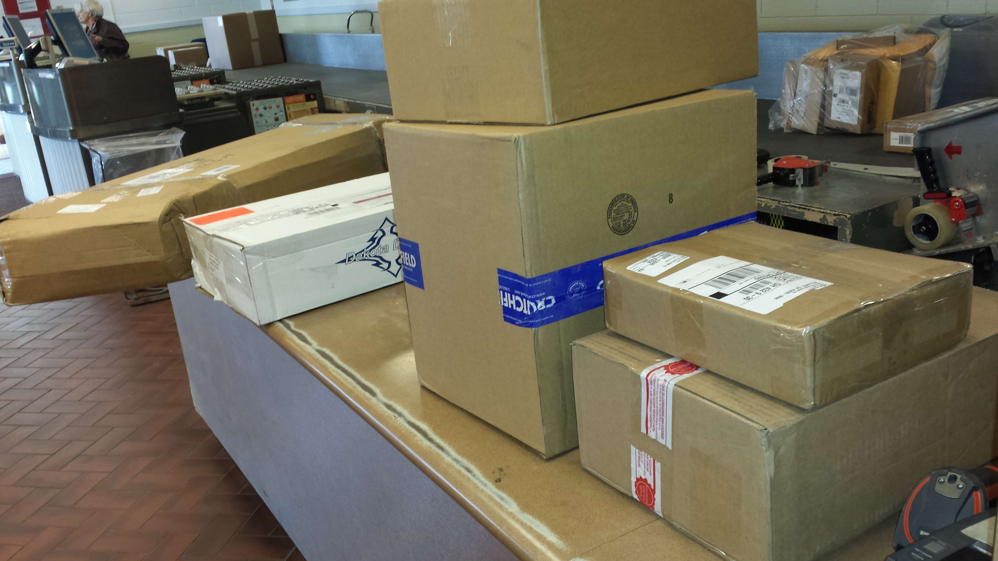
Before you know it, UPS had done its thing and the kit was ready for pickup. Why so many boxes you ask? Since the entire dash is coming apart, it's the perfect time to replace those disintegrating paper-cone 4x6's in the dash and get a modern head unit as well. (ok, and maybe some 6x9's , AMP and sub too)
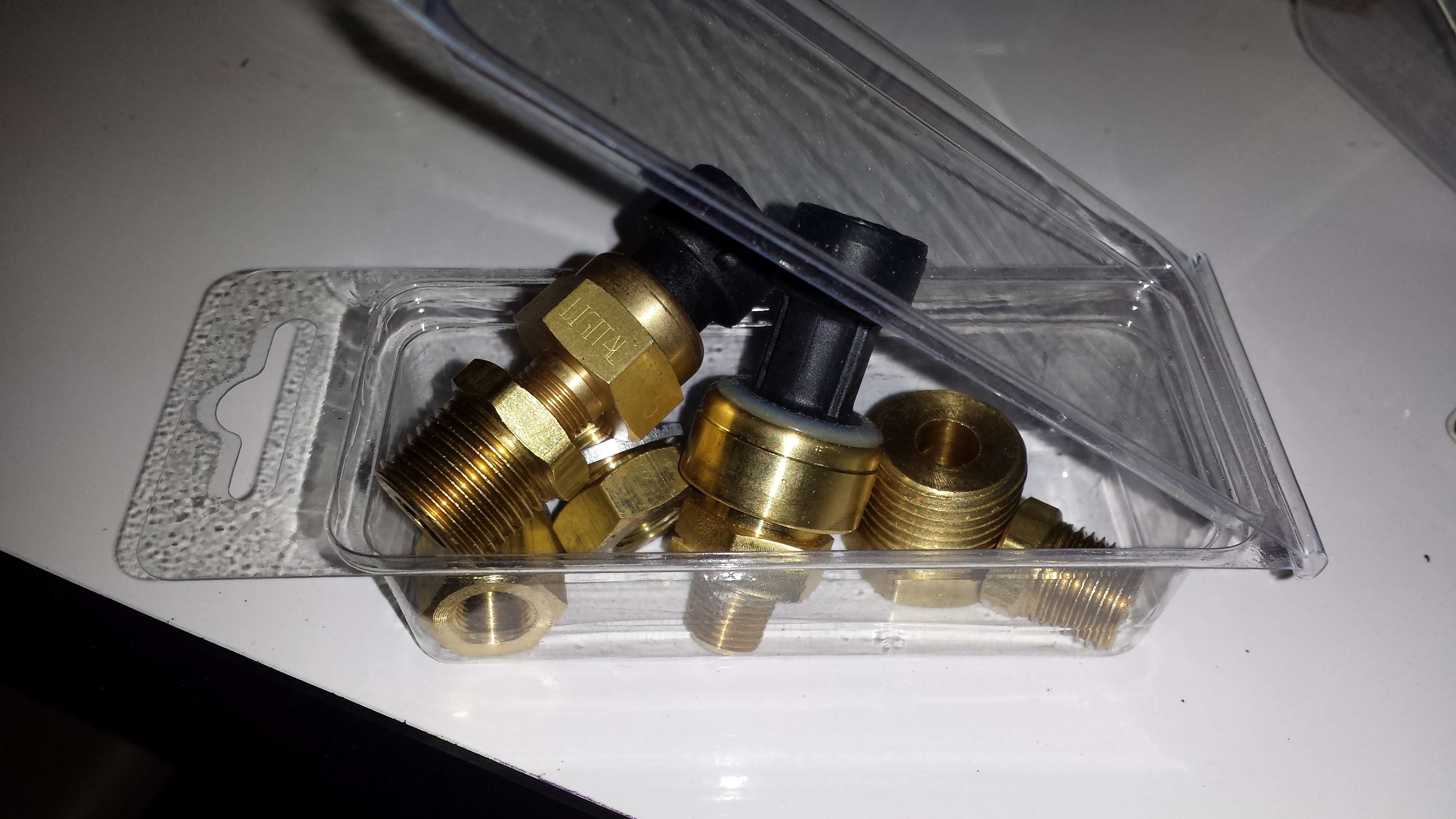
The items were packaged extremely well. Top marks for that. In the box were the gauges and green control box just as shown on Dakota Digital's website. Then there were some things you maybe didn't expect. Lets talk about those for a moment. What we have here isn't just a couple of new gauges, it is a totally new information center for the car. This means it takes over sensors and driver indicator functions pretty much entirely. As such, new sensors are in the kit along with adapters to fit whichever diameter threads your block has. (oil pressure and water temp pictured) The speed sensor was just so cool and compact that I completely forgot to photograph it.
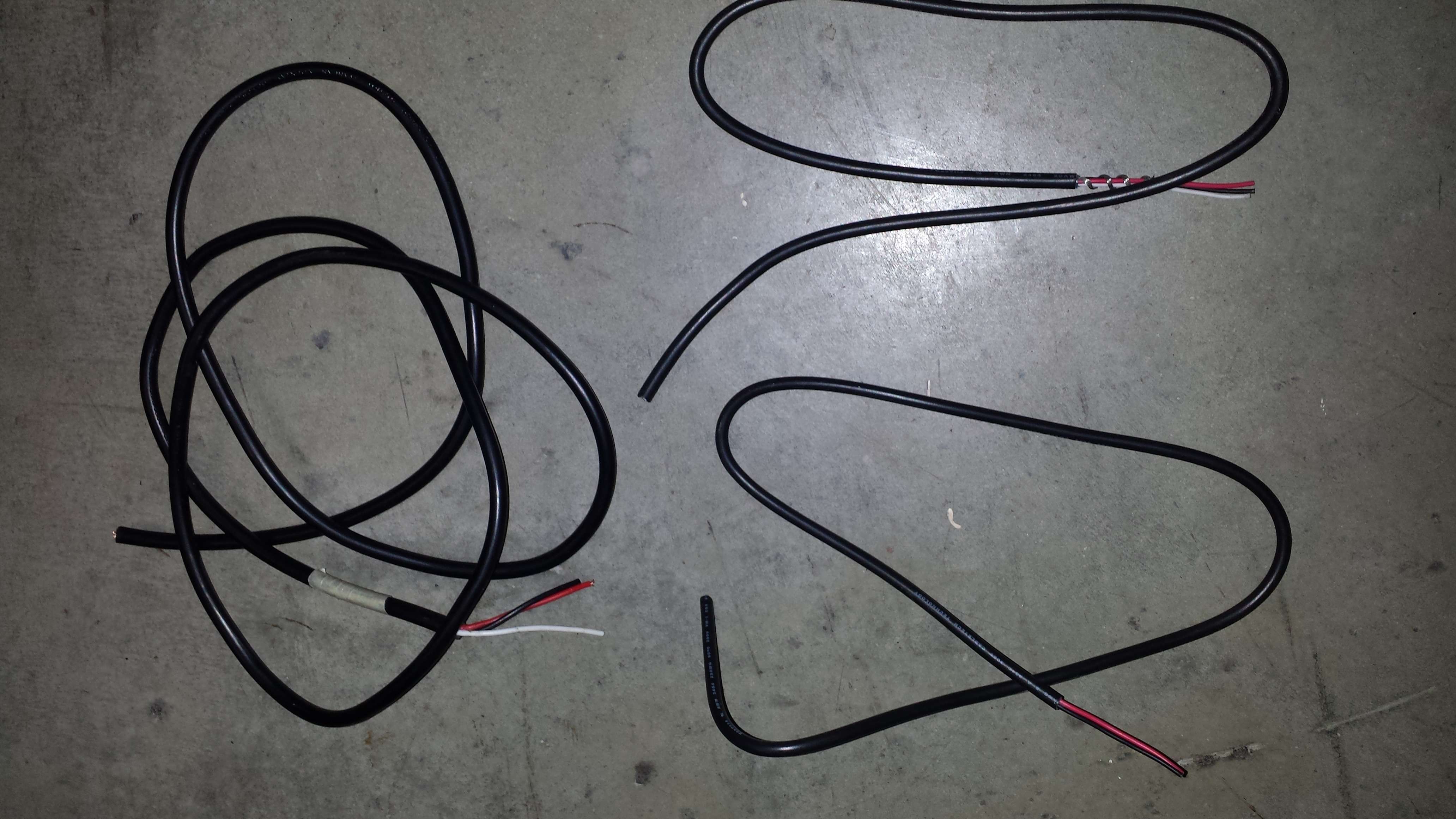
You will have generous lengths of sensor wire included as well. What you see here is what was trimmed after length was determined plus a little extra slack for easy maintenance.
In the box you will also find a whole bundle of CAT5 networking cables. What.. Networking cables you ask? Yup. This is getting pretty darn interesting already.

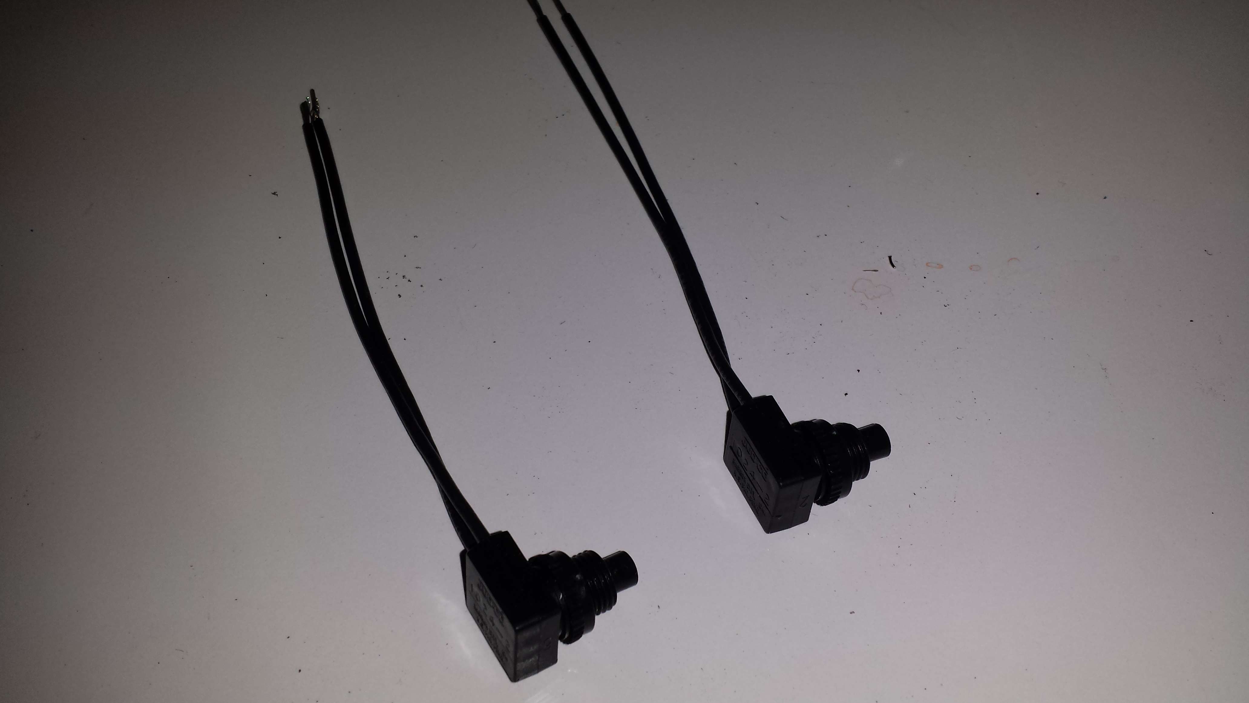
Next we have the momentary switches used for adjusting control unit settings such as the clock time and various other options.
Plastic inserts and brackets of various sizes exist as well. Here is one in particular we will be talking about.
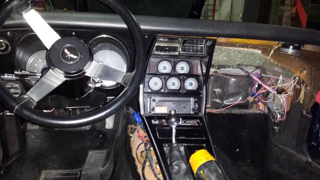
So let's get too it. If you have worked on C3 corvettes before, you know that 20-ish screws and bolts later, and the interior pretty much falls on the floor all on its own. haha. There are a couple of sticky points. 1. The dash pad raises up several inches for extra clearance, and this is enough. Removing it completely means bending it in the middle risking a wrinkle, crease or fold. ( It may have originally been dropped in prior to windshield install? )
2. When pulling the speed-o and tach cluster, the release for the headlight switch is awkward and the OEM wiring harness in all its weight and stiffness wants to hold it in. Careful persistence is the key.
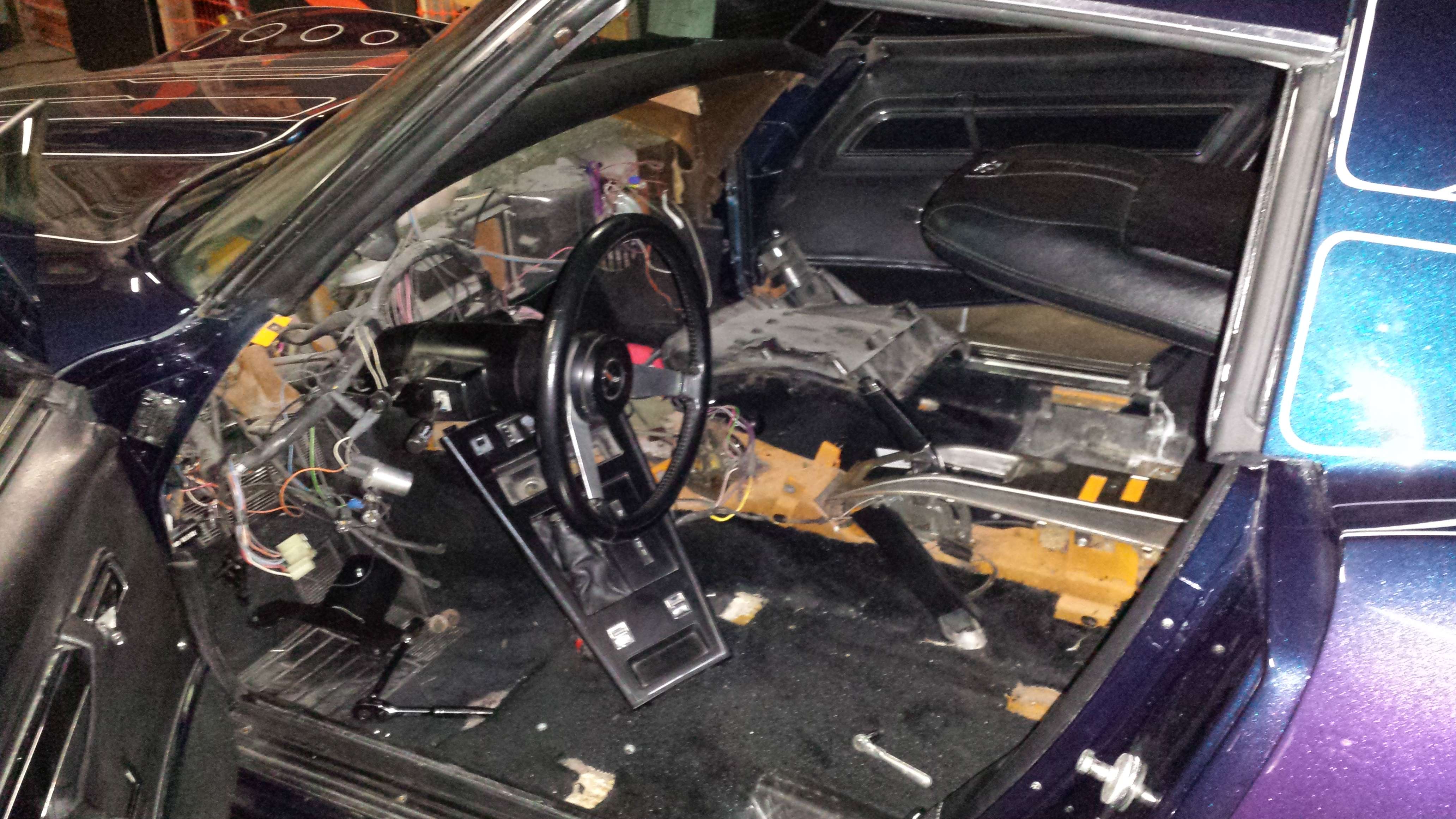
This is what you are left with! It looks like a huge mess!! Don't be intimidated, the hardest part is already done.
At this point, we get anxious to see how those gauges fit in those panels we just removed. We look to the instructions and find very detailed pictures of how and where to put screws and the included brackets. So good in fact that we are only momentarily confused and quickly realize our corvette speed/tach panel has an additional A/c vent (bottom left corner of the pic) their bracket holes don't line up with. Not to worry though, it took but a moment to drill an extra hole in the plastic bracket and we are good to go.
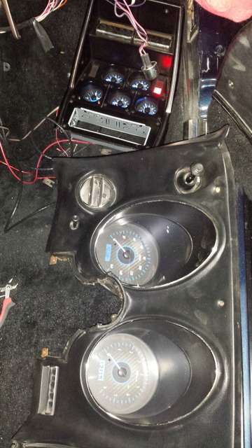
Let's compare old vs. new!
and both now in... easy as pie.
The 5 stack gauge cluster is just as well fitting, with a few choices to make. Remember that black rectangle piece I showed earlier? It is designed to black out the indicator windows for GEN and other various light bulb windows. We chose not to use that particular piece for two reasons. 1. I rather like having the GEN light give me a unbiased view of what the alternator is doing. 2. This low mileage vette still has the original alternator, not a new self-exciting single-wire, so the GEN light actually serves a purpose. We left it in. We also shaved the bezel for the single DIN radio.

The new gauges look just great! However, the kit provides no provision for filling in the hole the OEM clock adjustment lever required in the front of the bezel. We chose to drill a symmetrical hole on the other side of the clock and picked up some micro momentary switches. We mounted them here and will use them to control system setup, discarding the larger ones that came in the kit.
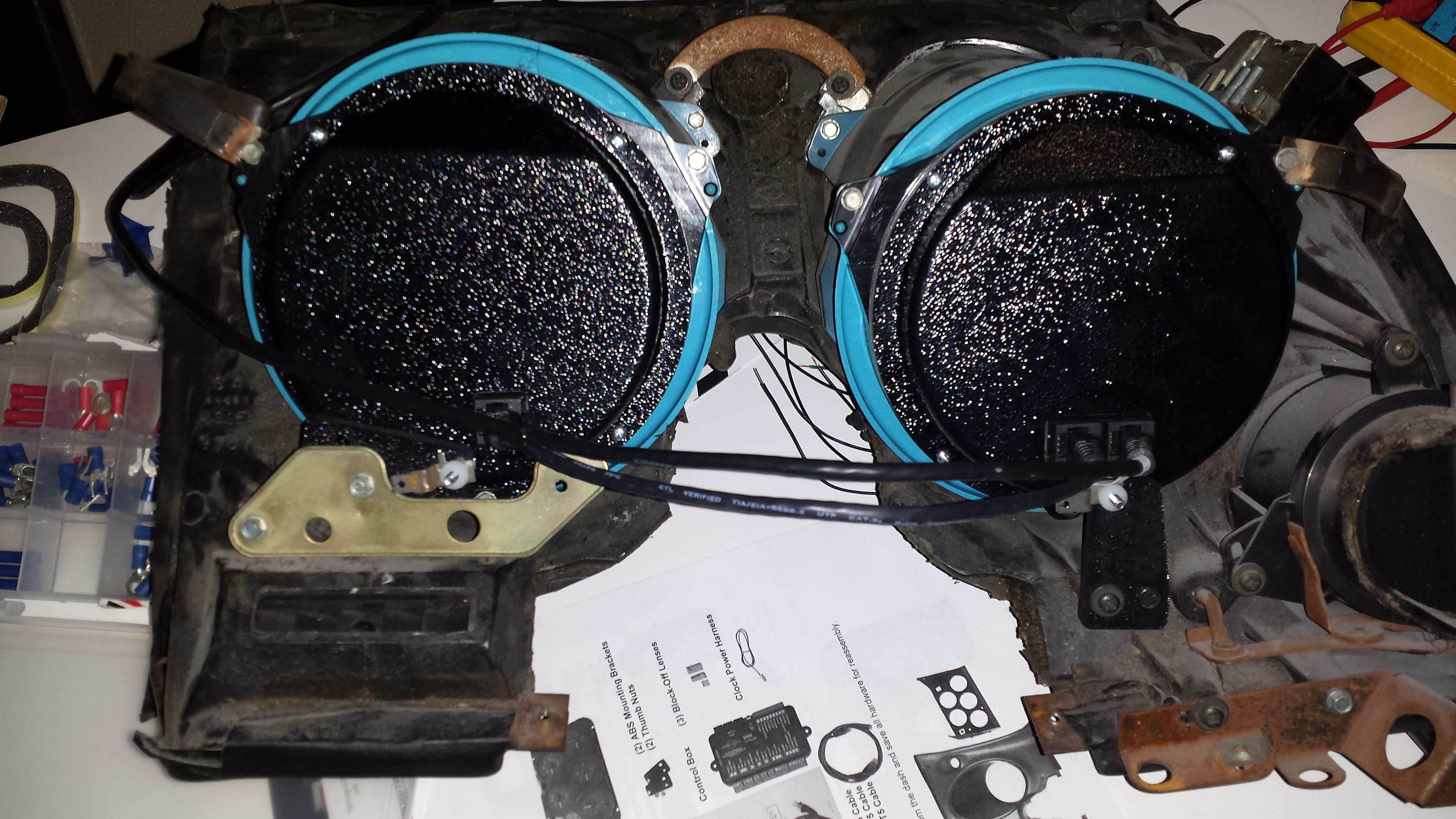
This seems like a good time to pause and get those new 4x6's put in the dash. The 2 metal brackets in the dash pad each have 4 posts to mount the speakers, the two posts with speed nuts are in a good location, the two posts without are not aligned so they are removed. Speaker cone clearance from the bracket's top side X brace is assured with a few spacers before mounting, and we are done.
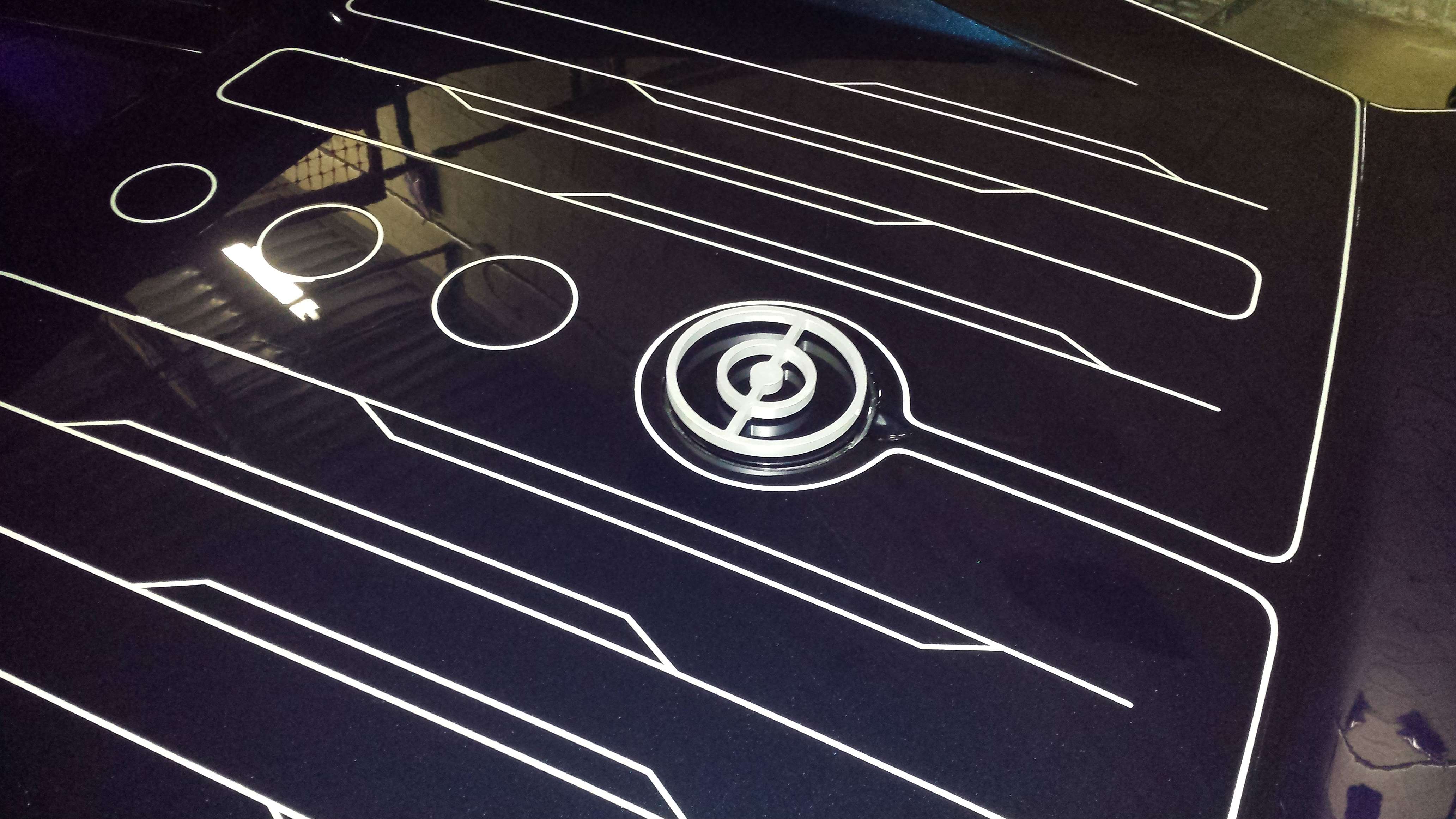
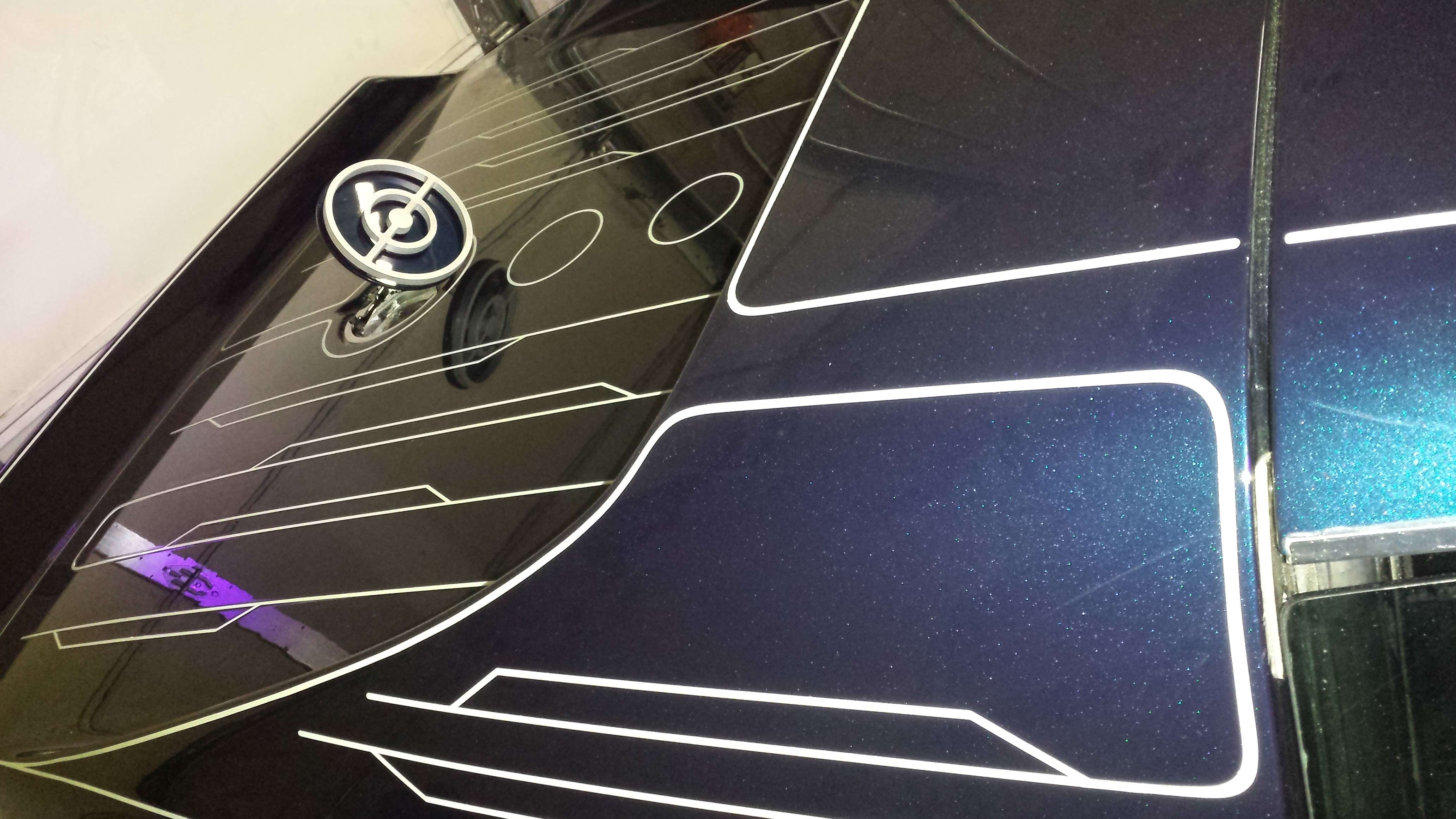
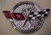
While we are talking stereo stuff, one quick item specific to the GRID CAR was rerunning the antenna wire. The corvette emblems on the gas cap seem far out of place amongst the glow-in-the-dark circuit designed pin striping, and the standard antenna was removed and the hole filled when the paint job was done. Solving two problems with one chunk of aluminum, I had a local machine shop create a raised "tron disc" I designed for the gas lid that doubles as a functional antenna.
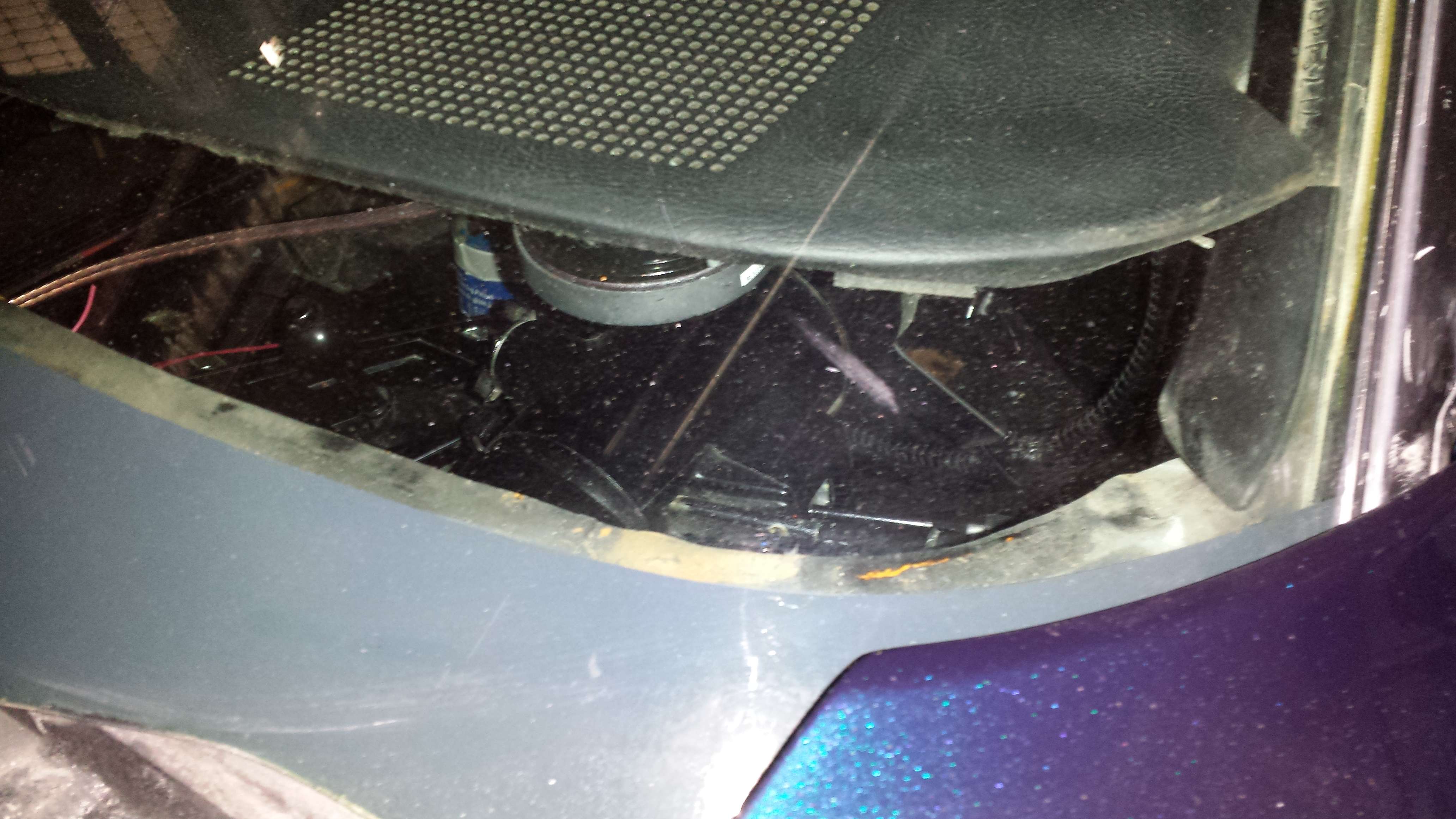
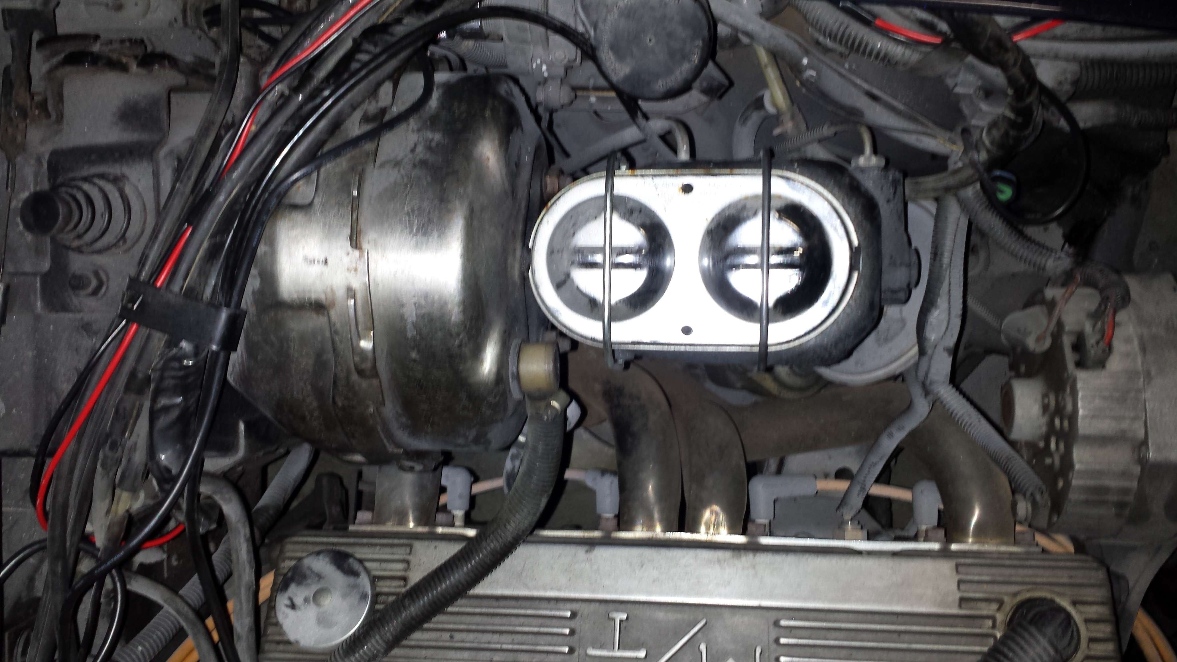
OK, let's jump back to the topic at hand. It is time to start wiring up the new stuff. First in line, those sensors we discussed earlier. Replacing sensors sounds like a chore, but in this single picture a trained eye can see all 3 sensors. Its that easy, just reach in , screw the old one out, screw the new one in. Since the mechanical speedometer cable comes out, there is a convenient hole to run the wires back in to the dash.
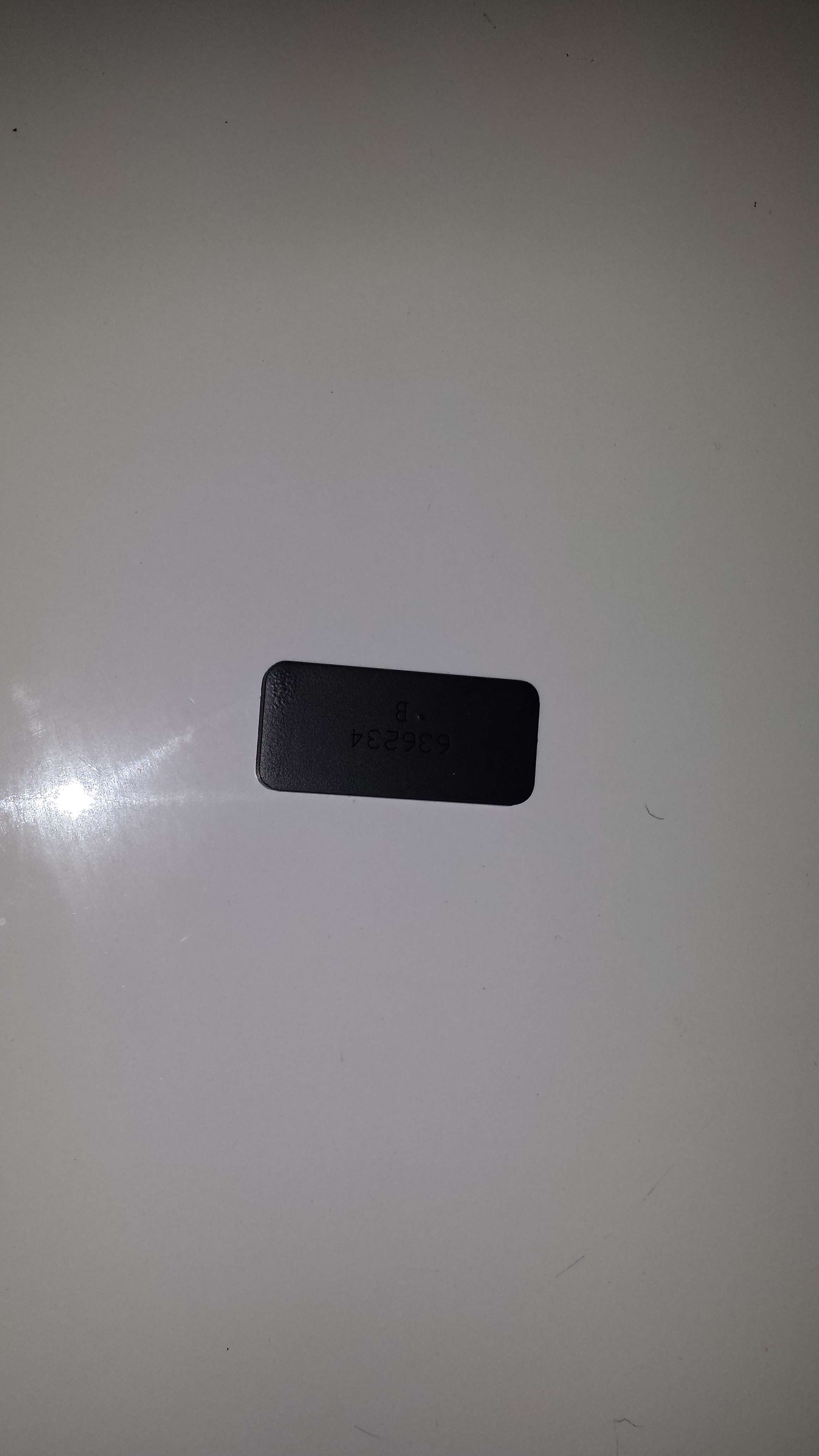
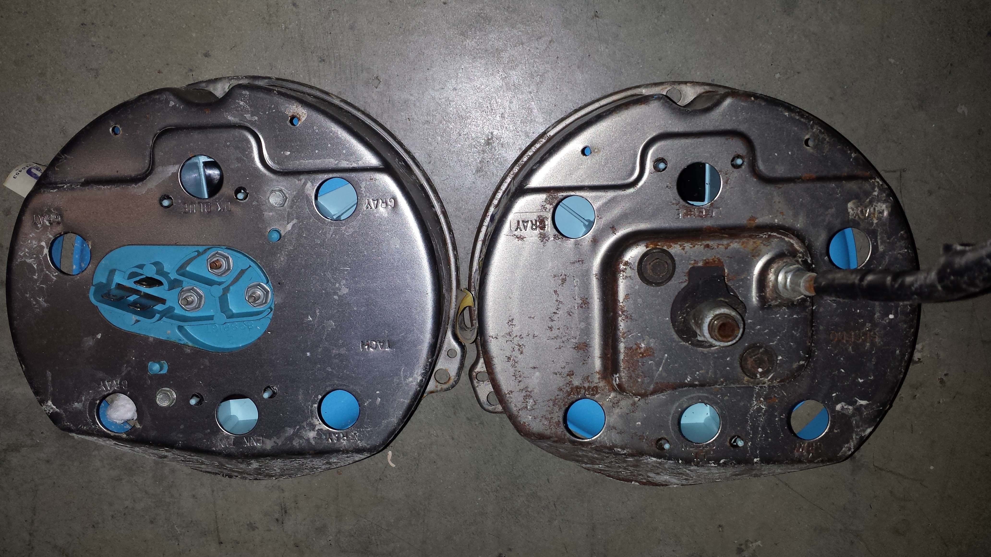
Now comes the time to convert the OEM gauge cluster wires over to the control box. Sounds tough to figure out, but the simple answer sits over in your trash bin. The color codes are on the back of the OEM gauges!
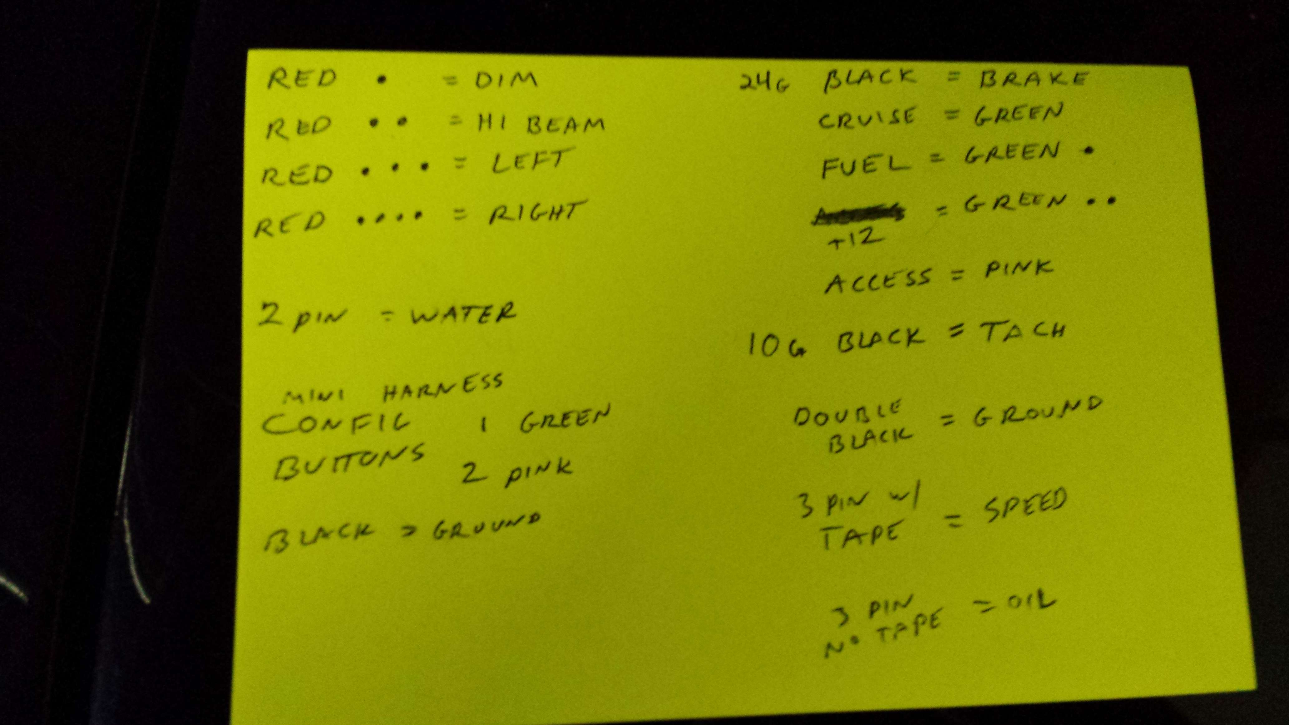
The colors do vary from year to year so I don't want to post too many specifics. I will say that "most" of the brown wires in the car serve different functions in different locations so be careful where in the harness you tap in to "a brown wire". As such, I had a friend run the jumpers as I wired them to the control box and we noted the jumper wires using dots on the sheathing via a Sharpie marker. Remember, for the most part these indicators already existed so its nothing tricky. One difference would be the cruise control on this car. The new kit has an indicator for cruise control where the OEM panel never did.
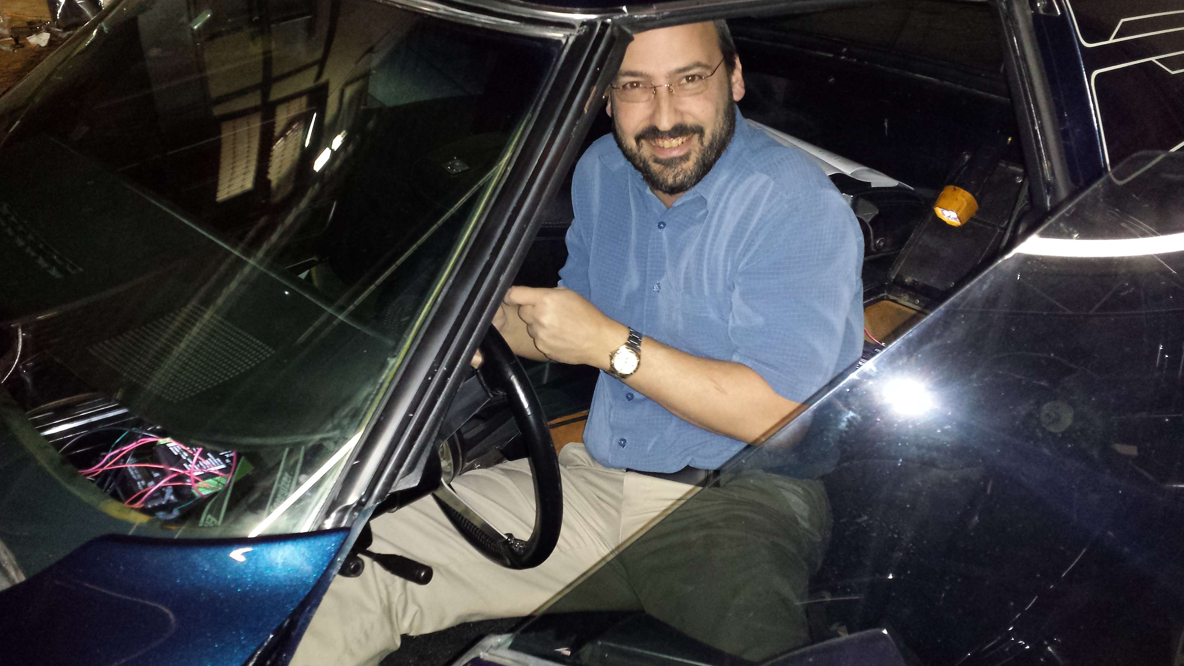
Here you can see my friend Marc finishing up one of the last wires.
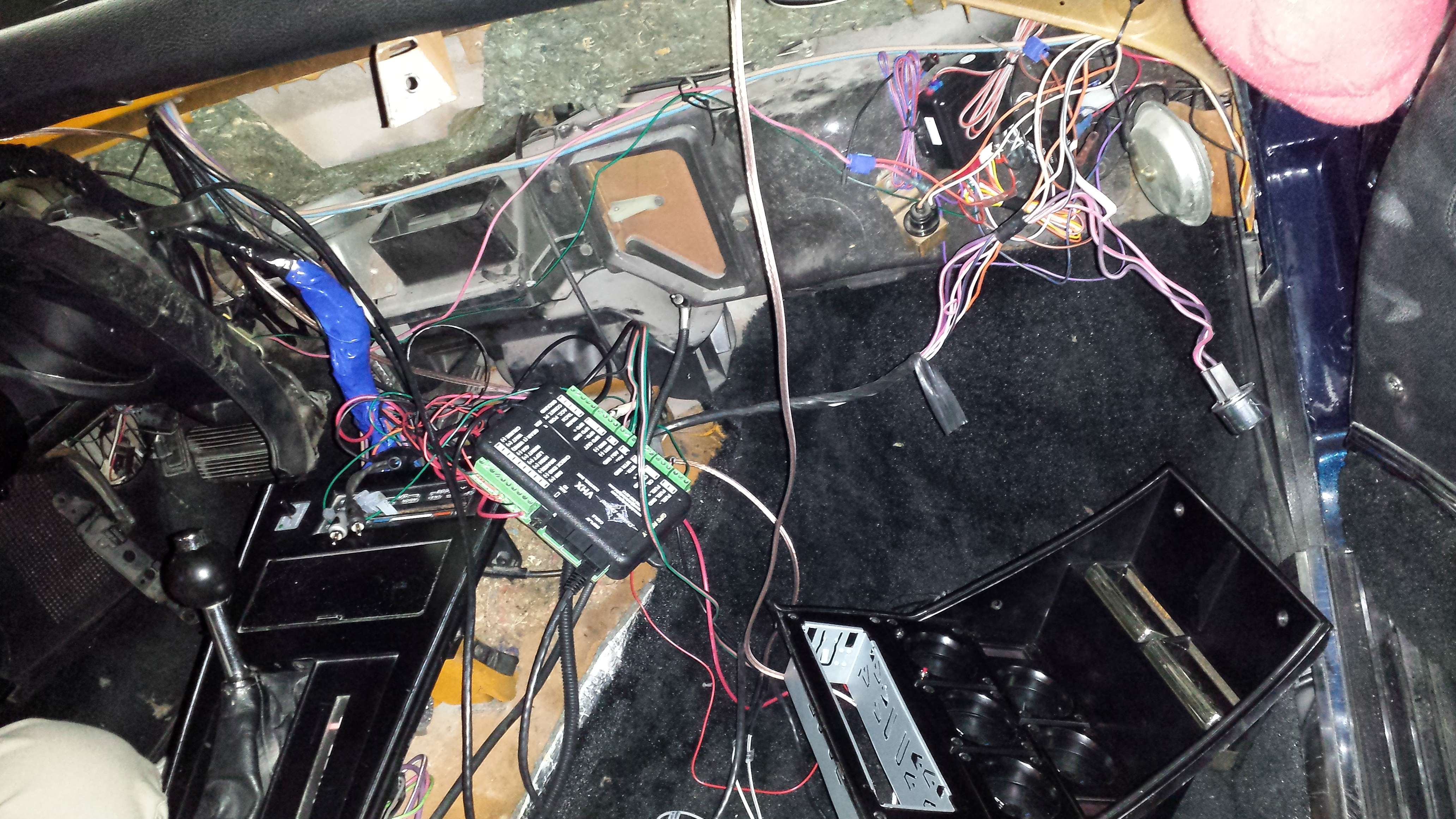
Before you know it we have all the connections to the box done.
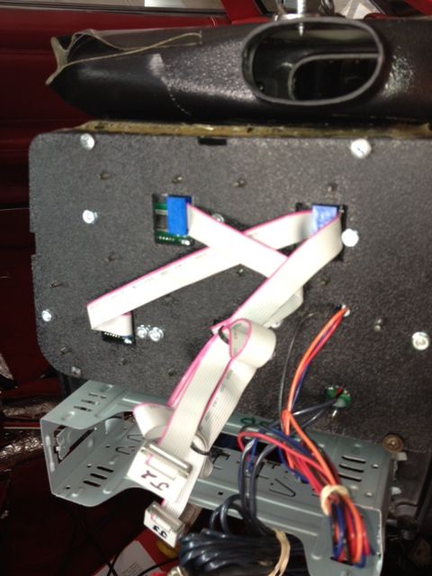
I know its hard to tell, but there are FEWER wires in the car now, not more. its getting cleaner by the minute. We trim and tie up what we can and wrap the new jumpers in blue wrap. Those network cables run from the control box to the 2 gauge clusters and make everything so easy!
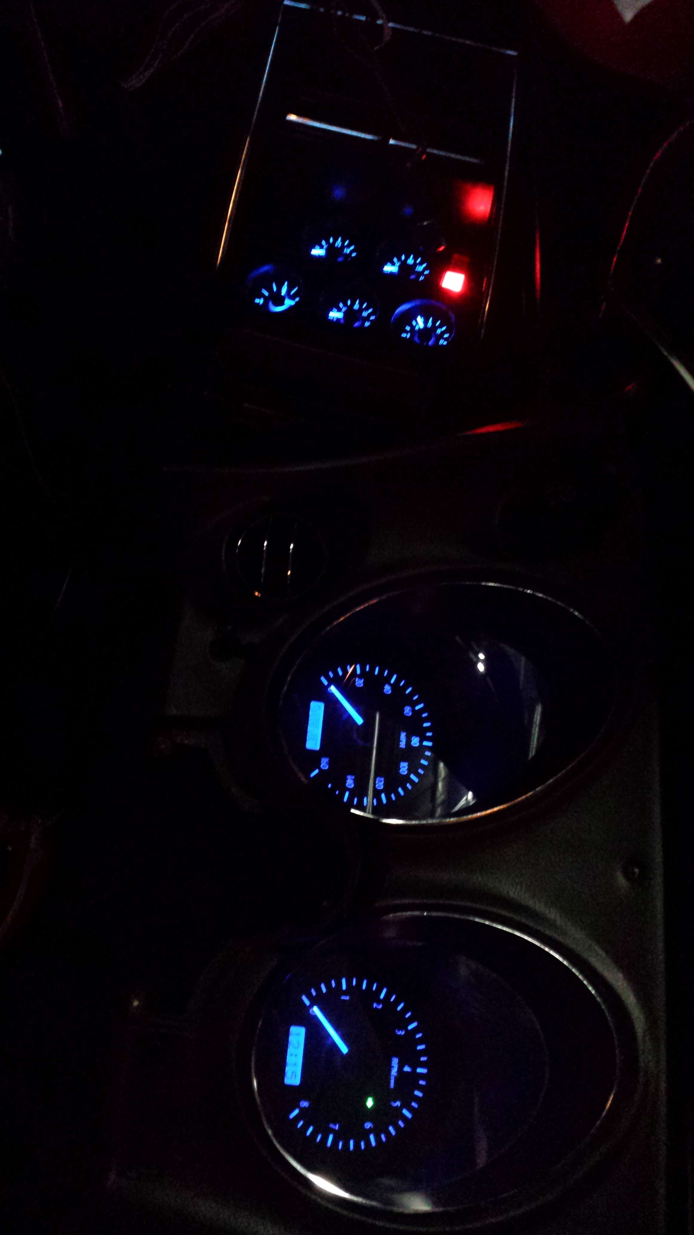
Feeling confident, we connect the power and do a power on test. After one adjustment everything is working great and the illumination mode is rockin'!!
In Part 2 we will cover reassembly, control box calibration , features, and a video of operation so you can get a better appreciation for the fantastic "presence and feel" this package gives, right down to the turn signals.
Let's start from the beginning. Ordering online was fast and easy. You will be prompted to choose MPH/KMH , colors, and any optional modules which I opted out of for now. I was contacted by Dakota Digital after placing the order and they informed me of production times of various color combinations. I knew I wanted blue-lit since the GRID CAR is blue, but I was on the fence about the back face color. The silver might look awesome in an all black interior, or it might be too much of a contrast feeling out of place and awkward. The much shorter lead time on the carbon fiber look gauges made the tie-breaker decision easy. First lesson learned, if you want a set of VHX gauges in your car, plan ahead and place your order early.
Before you know it, UPS had done its thing and the kit was ready for pickup. Why so many boxes you ask? Since the entire dash is coming apart, it's the perfect time to replace those disintegrating paper-cone 4x6's in the dash and get a modern head unit as well. (ok, and maybe some 6x9's , AMP and sub too)
The items were packaged extremely well. Top marks for that. In the box were the gauges and green control box just as shown on Dakota Digital's website. Then there were some things you maybe didn't expect. Lets talk about those for a moment. What we have here isn't just a couple of new gauges, it is a totally new information center for the car. This means it takes over sensors and driver indicator functions pretty much entirely. As such, new sensors are in the kit along with adapters to fit whichever diameter threads your block has. (oil pressure and water temp pictured) The speed sensor was just so cool and compact that I completely forgot to photograph it.
You will have generous lengths of sensor wire included as well. What you see here is what was trimmed after length was determined plus a little extra slack for easy maintenance.
In the box you will also find a whole bundle of CAT5 networking cables. What.. Networking cables you ask? Yup. This is getting pretty darn interesting already.
Next we have the momentary switches used for adjusting control unit settings such as the clock time and various other options.
Plastic inserts and brackets of various sizes exist as well. Here is one in particular we will be talking about.
So let's get too it. If you have worked on C3 corvettes before, you know that 20-ish screws and bolts later, and the interior pretty much falls on the floor all on its own. haha. There are a couple of sticky points. 1. The dash pad raises up several inches for extra clearance, and this is enough. Removing it completely means bending it in the middle risking a wrinkle, crease or fold. ( It may have originally been dropped in prior to windshield install? )
2. When pulling the speed-o and tach cluster, the release for the headlight switch is awkward and the OEM wiring harness in all its weight and stiffness wants to hold it in. Careful persistence is the key.
This is what you are left with! It looks like a huge mess!! Don't be intimidated, the hardest part is already done.
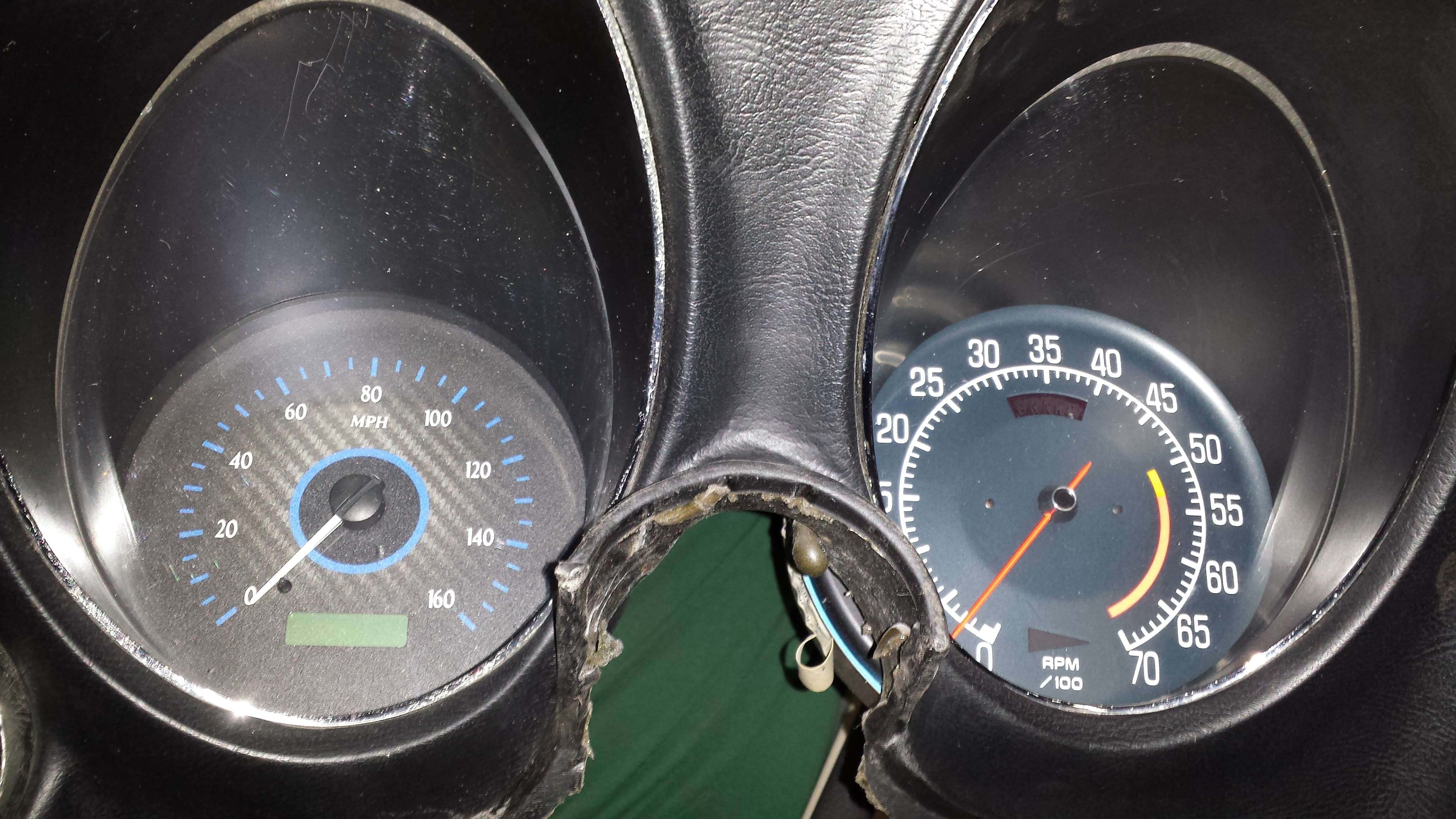
At this point, we get anxious to see how those gauges fit in those panels we just removed. We look to the instructions and find very detailed pictures of how and where to put screws and the included brackets. So good in fact that we are only momentarily confused and quickly realize our corvette speed/tach panel has an additional A/c vent (bottom left corner of the pic) their bracket holes don't line up with. Not to worry though, it took but a moment to drill an extra hole in the plastic bracket and we are good to go.
Let's compare old vs. new!
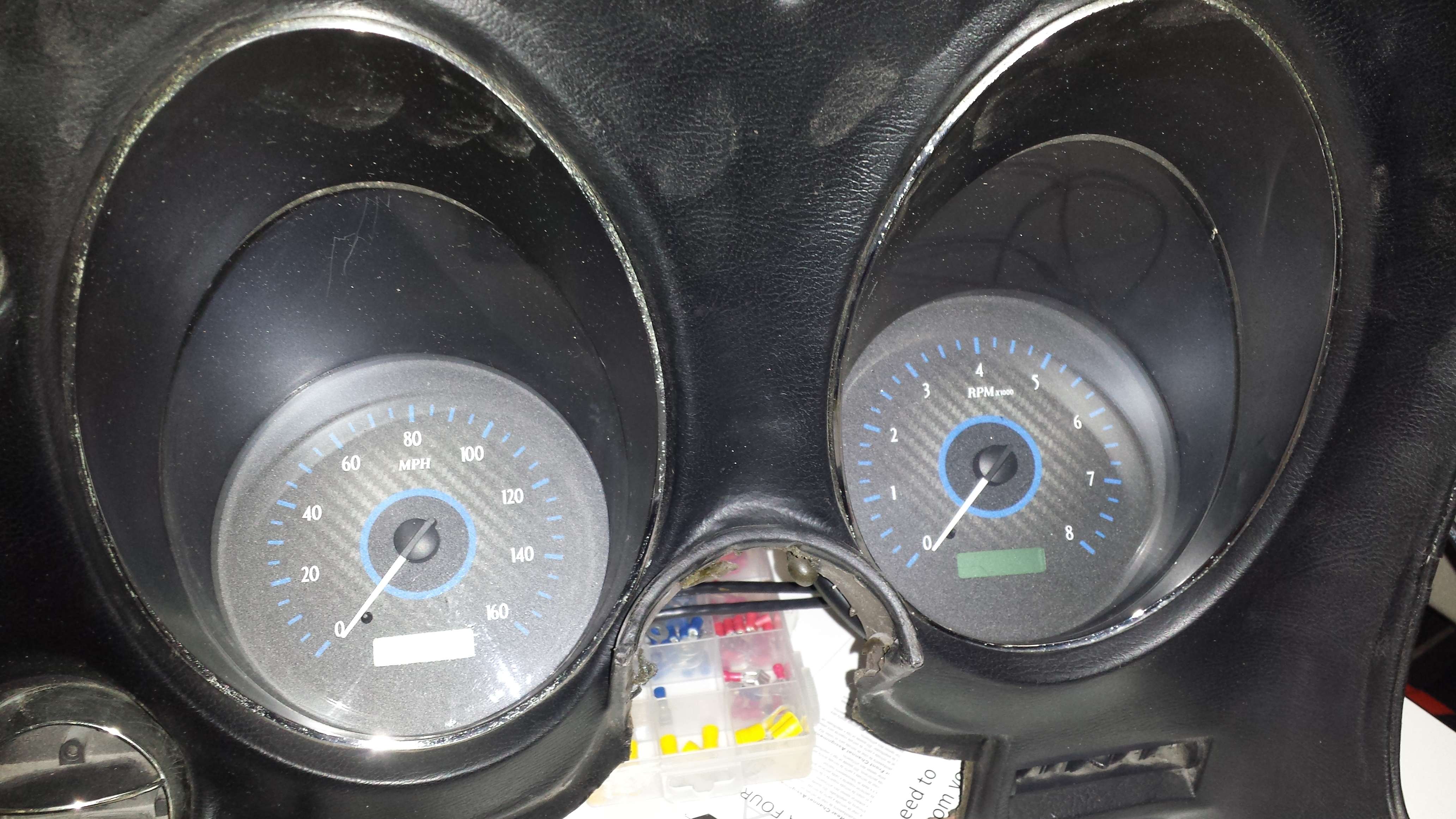
and both now in... easy as pie.
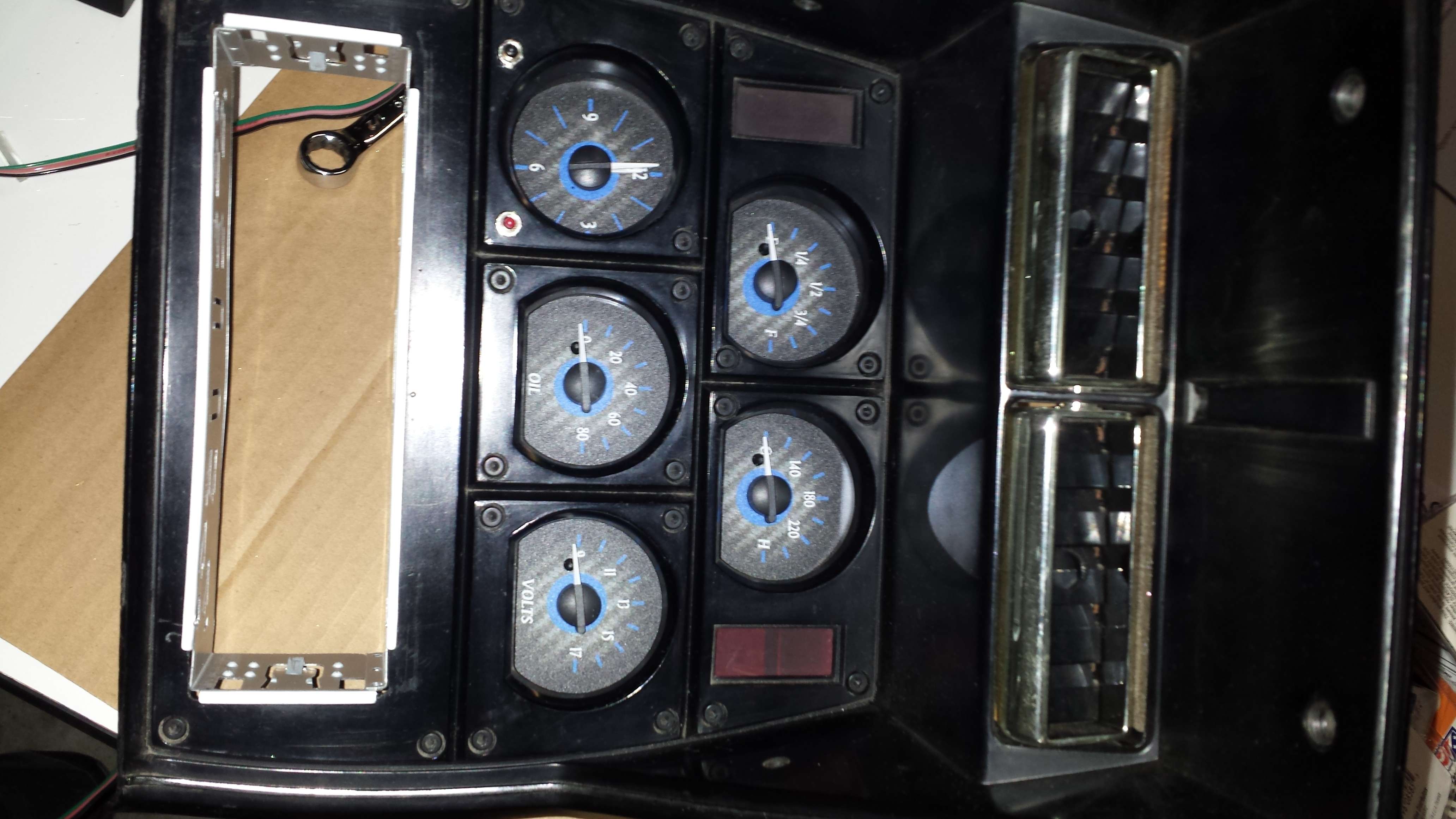
The 5 stack gauge cluster is just as well fitting, with a few choices to make. Remember that black rectangle piece I showed earlier? It is designed to black out the indicator windows for GEN and other various light bulb windows. We chose not to use that particular piece for two reasons. 1. I rather like having the GEN light give me a unbiased view of what the alternator is doing. 2. This low mileage vette still has the original alternator, not a new self-exciting single-wire, so the GEN light actually serves a purpose. We left it in. We also shaved the bezel for the single DIN radio.
The new gauges look just great! However, the kit provides no provision for filling in the hole the OEM clock adjustment lever required in the front of the bezel. We chose to drill a symmetrical hole on the other side of the clock and picked up some micro momentary switches. We mounted them here and will use them to control system setup, discarding the larger ones that came in the kit.
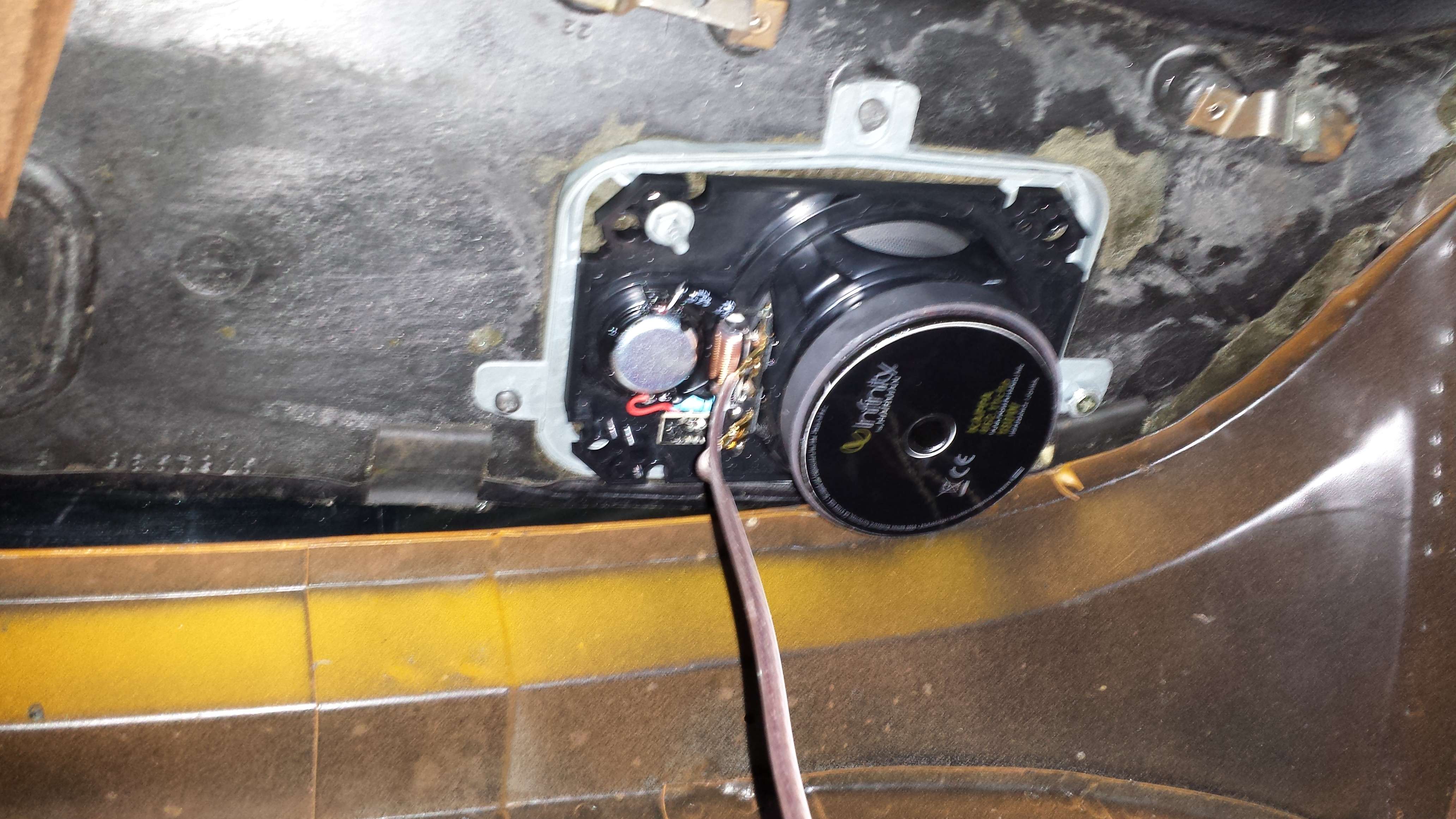
This seems like a good time to pause and get those new 4x6's put in the dash. The 2 metal brackets in the dash pad each have 4 posts to mount the speakers, the two posts with speed nuts are in a good location, the two posts without are not aligned so they are removed. Speaker cone clearance from the bracket's top side X brace is assured with a few spacers before mounting, and we are done.
While we are talking stereo stuff, one quick item specific to the GRID CAR was rerunning the antenna wire. The corvette emblems on the gas cap seem far out of place amongst the glow-in-the-dark circuit designed pin striping, and the standard antenna was removed and the hole filled when the paint job was done. Solving two problems with one chunk of aluminum, I had a local machine shop create a raised "tron disc" I designed for the gas lid that doubles as a functional antenna.
OK, let's jump back to the topic at hand. It is time to start wiring up the new stuff. First in line, those sensors we discussed earlier. Replacing sensors sounds like a chore, but in this single picture a trained eye can see all 3 sensors. Its that easy, just reach in , screw the old one out, screw the new one in. Since the mechanical speedometer cable comes out, there is a convenient hole to run the wires back in to the dash.
Now comes the time to convert the OEM gauge cluster wires over to the control box. Sounds tough to figure out, but the simple answer sits over in your trash bin. The color codes are on the back of the OEM gauges!
The colors do vary from year to year so I don't want to post too many specifics. I will say that "most" of the brown wires in the car serve different functions in different locations so be careful where in the harness you tap in to "a brown wire". As such, I had a friend run the jumpers as I wired them to the control box and we noted the jumper wires using dots on the sheathing via a Sharpie marker. Remember, for the most part these indicators already existed so its nothing tricky. One difference would be the cruise control on this car. The new kit has an indicator for cruise control where the OEM panel never did.
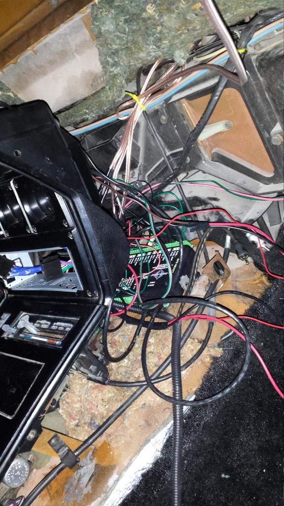
Here you can see my friend Marc finishing up one of the last wires.
Before you know it we have all the connections to the box done.
I know its hard to tell, but there are FEWER wires in the car now, not more. its getting cleaner by the minute. We trim and tie up what we can and wrap the new jumpers in blue wrap. Those network cables run from the control box to the 2 gauge clusters and make everything so easy!
Feeling confident, we connect the power and do a power on test. After one adjustment everything is working great and the illumination mode is rockin'!!
In Part 2 we will cover reassembly, control box calibration , features, and a video of operation so you can get a better appreciation for the fantastic "presence and feel" this package gives, right down to the turn signals.
Last edited by hyteck9; 05-09-2014 at 08:58 AM.
05-01-2014, 05:48 PM
#4


Looking fantastic !!


 05-07-2014, 05:18 PM
#7


Awesome writeup!
 05-16-2014, 10:28 AM
#9
Burning Brakes
Thread Starter
Part 2 is finally here!
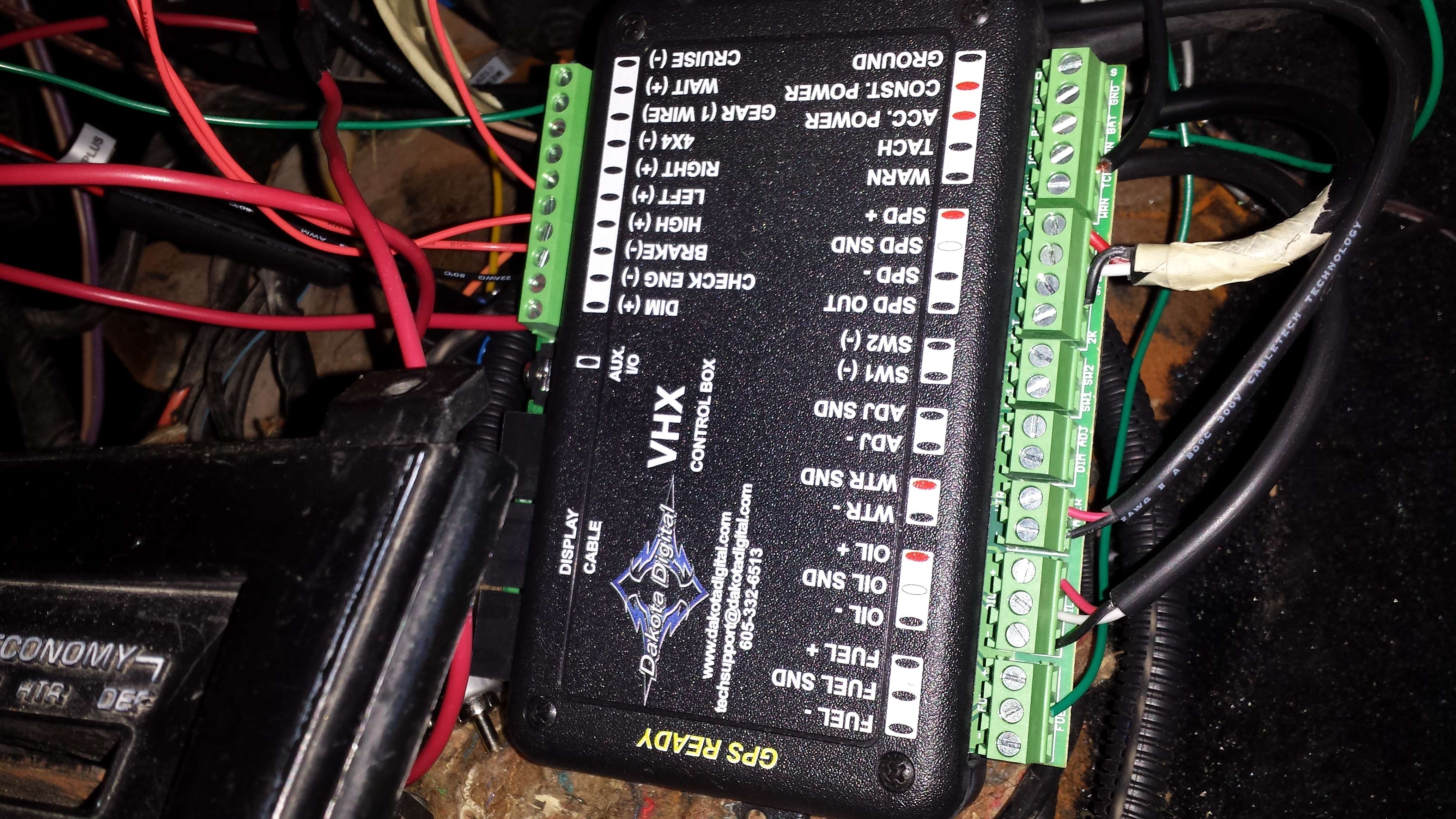
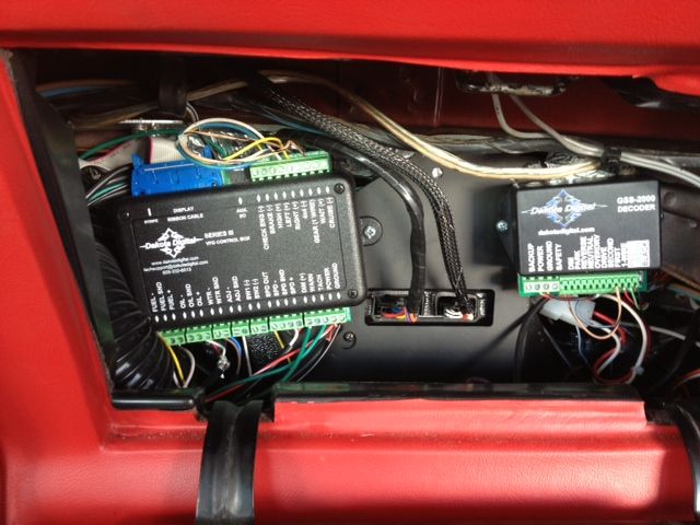
We left off with a power test that had promising results. The task of reassembly now begins and the very first thing we had to do was choose a location for our control box. The instructions warn not to get the control box too close to the ignition distributor even if you have a firewall between the two. With that cautious note in mind, we decided to mount the box on the center tunnel behind the 5 gauge cluster and under the radio. Optimistic as I am on the success of this endeavor, I still felt a temporary mount was best should maintenance be needed so two strips of velcro were used to hold it in place. Let's do a test-fit...
The box sits nicely and none of the wires feel cramped or twisted up. Great! Let's get those wires sorted and put the radio in to assure clearance.
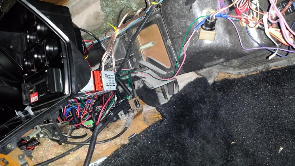
Looks like there is plenty of room. Great! (again!). There is a method to the madness of the wires too. We left the wires loose (unwrapped) to encourage some flexibility on bumps and vibrations (like at idle haha), so the screw terminals of the box wouldn't have to take the brunt of it and potentially work a connection loose. We reconnected the battery and did another quick power on test to make sure we were in good shape, and we were. One quick side note I will toss out there. We found a large number of wire-tap connectors in this car inside and out. Likely from the previous owner installing CB radios, a different security system, etc. We removed every single one of them and soldered the connections instead. These stupid things are the devil !!!!
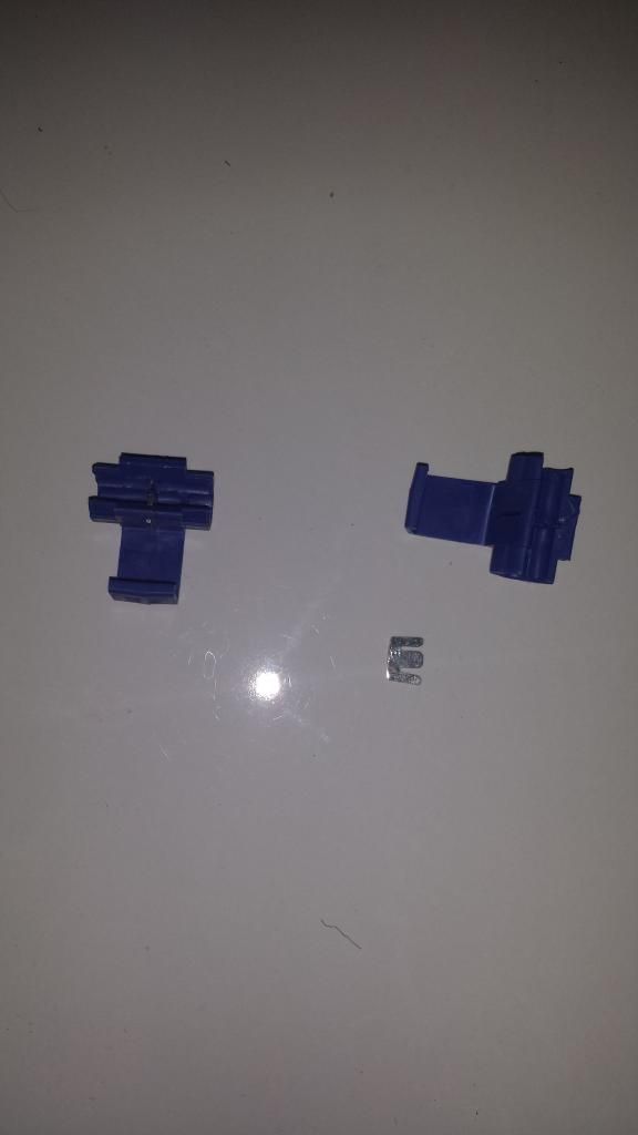
This isn't just a generic opinion, its experience talking. Don't use them, get rid of them, don't even think about them, and your life will be better for it. Even "if" they get a good bite, which they usually don't, it is limited contact and won't last. But don't take my word for it, you can read more HERE.
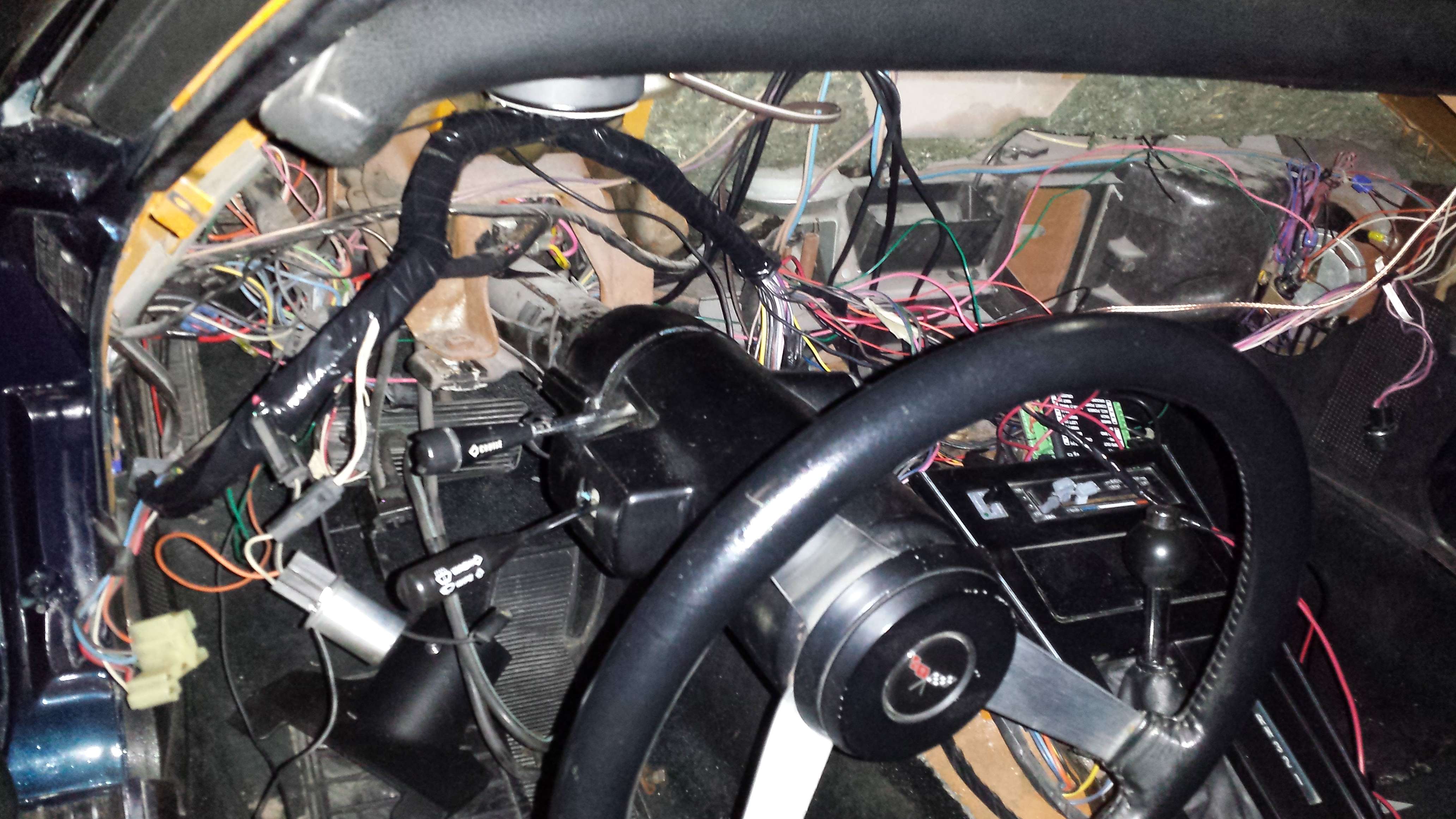
Not only did we tidy up all the electrical connections, but this is a wonderful chance to take a screw driver or ratchet to all the other supporting brackets and braces you encounter and tighten them up a bit. We are talking about a car that is almost 40 years old at this point after all. Let's get that driver's side gauge cluster put back on next. Once it is on we will have a much better sense of the completed product, more room in the car to finish our work, and a final resting position for the wiring harness. We work the cluster back and adjust the harness over the top of it as before, making sure to mind the lip that goes across the steering wheel column. So far , so good.
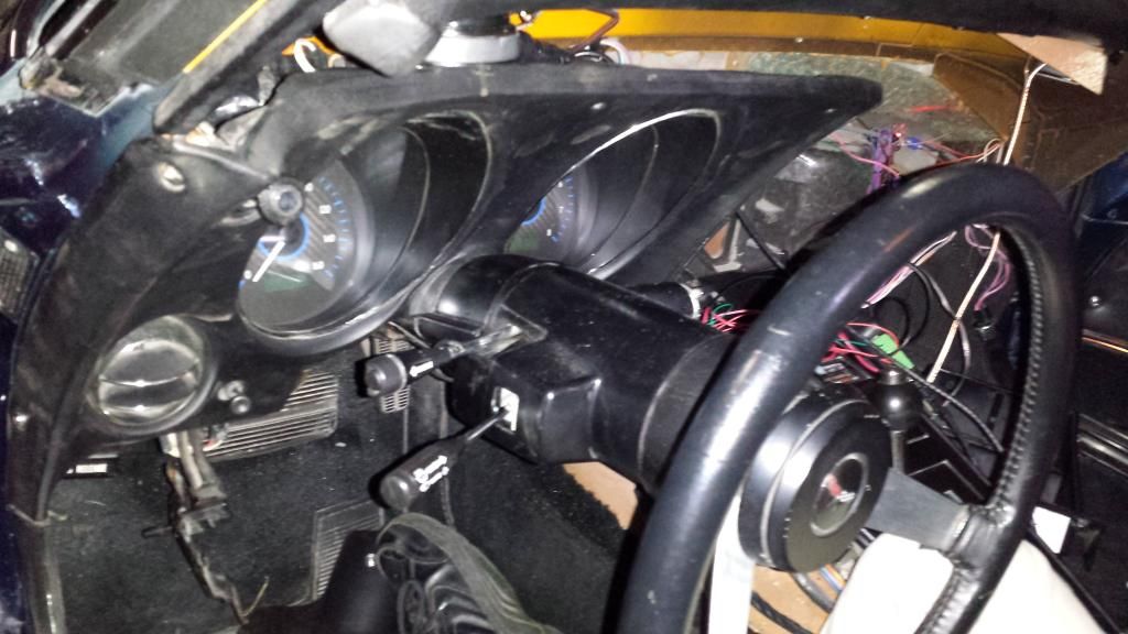
Once everything looks properly aligned we lock it back in to place and carefully drop the dash. The dash pad has a good bit of left-right movement so DO NOT use it as your eyeball guide to where the cluster goes. Focus on the steering column and the inner door frame and bring the dash pad in to match.
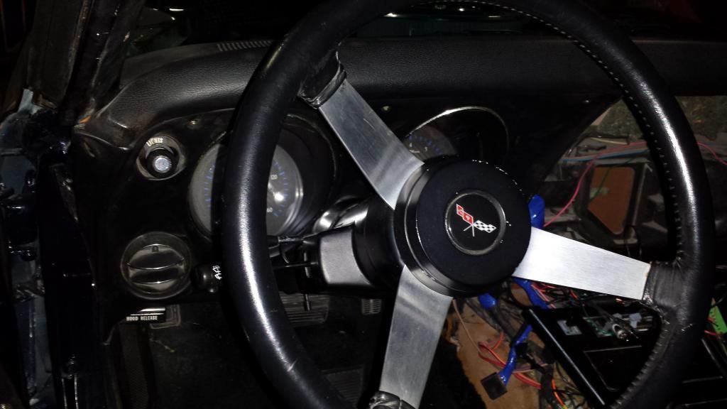
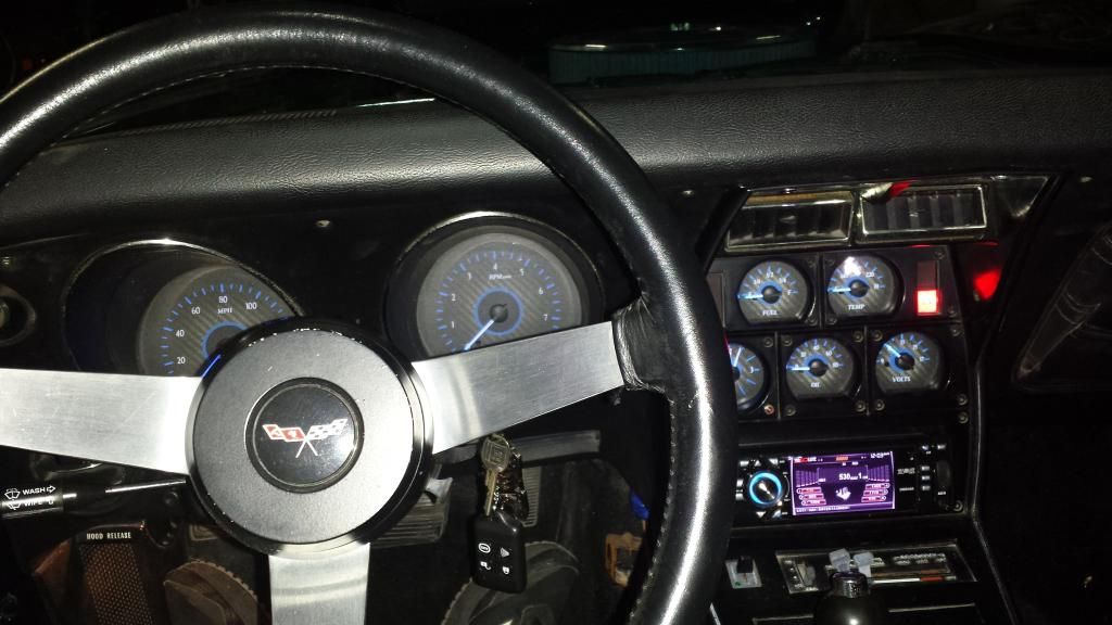
Wow, now we can see what kind of final product we are going to have. Looks very promising. Let's temporarily set the 5 gauge cluster in place, reconnect the battery and do one last power on test before we finish up the passenger's side dash panel since we have moved the wiring harness one last time.
NOTE: We realized the tach filter near the distributor was preventing the control box from picking up the ignition signal for the tach and bypassed it.
Looks great! Time to pull out the 5gauge cluster, put the passenger panel in, then button it all up. (We take a moment and run the RCA's for the AMP threw the center tunnel too. ) And before you know it, the car is back together! Yeah!
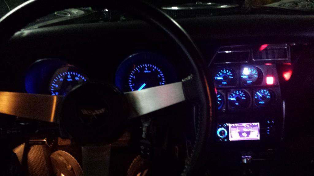
And that super awesome illumination test... not the best picture, but hopefully the setup and calibration video can show it off better.
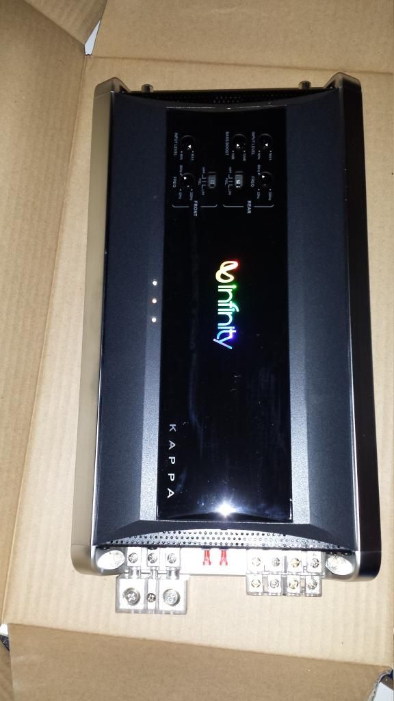
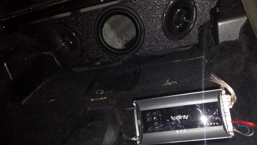
Before we put the seats back in we have to get the AMP and speaker box installed. The AMP chosen is a 4 channel Infinity (bridged to 3) that is powerful, great to look at, runs cool and is nice and thin to go behind the seat.
The speaker box was ordered at the CarAudioFactory and holds 2 6x9's and one shallow mount small enclosure 12" sub. The box is coated in a "rhino-liner" type coating which ensures its air tight and looks great. Of all the things that could have gone wrong on this project, one of the wire connectors on the back of the speaker box didn't take well to shipping and rattled like a can of pennies! Super Annoying. We shipped a replacement and everything was ready to go. ( I placed a quarter on the box to show its slim figure.)
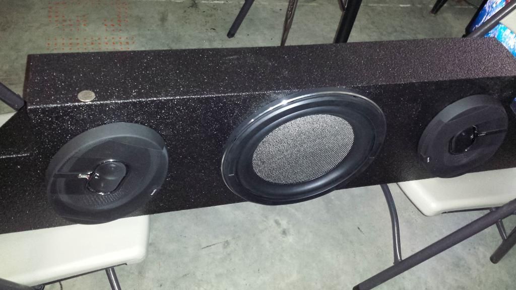
Some of the rear interior panels must come off or at least be loosened to slide the box back, but once in, everything fits very well and looks cool. It sounds even better! Super happy with this setup. I think there is still room for the T-tops too, but I admit I didn't take the time to try it.
Now the seats go back in and we are all set to pass you on to the setup and calibration video. One last thing I have to say. The maiden voyage of the GRID CAR after this install was an astounding contrast to the car's previous condition. The car was tight!! No rattles, squeaks, or annoying light flickers. Even the thump of the sub kicking didn't seem to cause excess noise. If that wasn't amazing enough, the weight of the speaker box over the rear wheels really improved the ride too! It was a totally different beast! It was like getting a free suspension upgrade.
OK, For the rest of the story please check out the video I posted. If you have additional questions, feel free to ask. Thanks for reading!
"I highly recommend it!"
P.S. The GRID CAR will be on display at Corvettes of Carlisle this year, come see it in person if you like or ask questions face to face. Thanks!
We left off with a power test that had promising results. The task of reassembly now begins and the very first thing we had to do was choose a location for our control box. The instructions warn not to get the control box too close to the ignition distributor even if you have a firewall between the two. With that cautious note in mind, we decided to mount the box on the center tunnel behind the 5 gauge cluster and under the radio. Optimistic as I am on the success of this endeavor, I still felt a temporary mount was best should maintenance be needed so two strips of velcro were used to hold it in place. Let's do a test-fit...
The box sits nicely and none of the wires feel cramped or twisted up. Great! Let's get those wires sorted and put the radio in to assure clearance.
Looks like there is plenty of room. Great! (again!). There is a method to the madness of the wires too. We left the wires loose (unwrapped) to encourage some flexibility on bumps and vibrations (like at idle haha), so the screw terminals of the box wouldn't have to take the brunt of it and potentially work a connection loose. We reconnected the battery and did another quick power on test to make sure we were in good shape, and we were. One quick side note I will toss out there. We found a large number of wire-tap connectors in this car inside and out. Likely from the previous owner installing CB radios, a different security system, etc. We removed every single one of them and soldered the connections instead. These stupid things are the devil !!!!
This isn't just a generic opinion, its experience talking. Don't use them, get rid of them, don't even think about them, and your life will be better for it. Even "if" they get a good bite, which they usually don't, it is limited contact and won't last. But don't take my word for it, you can read more HERE.
Not only did we tidy up all the electrical connections, but this is a wonderful chance to take a screw driver or ratchet to all the other supporting brackets and braces you encounter and tighten them up a bit. We are talking about a car that is almost 40 years old at this point after all. Let's get that driver's side gauge cluster put back on next. Once it is on we will have a much better sense of the completed product, more room in the car to finish our work, and a final resting position for the wiring harness. We work the cluster back and adjust the harness over the top of it as before, making sure to mind the lip that goes across the steering wheel column. So far , so good.
Once everything looks properly aligned we lock it back in to place and carefully drop the dash. The dash pad has a good bit of left-right movement so DO NOT use it as your eyeball guide to where the cluster goes. Focus on the steering column and the inner door frame and bring the dash pad in to match.
Wow, now we can see what kind of final product we are going to have. Looks very promising. Let's temporarily set the 5 gauge cluster in place, reconnect the battery and do one last power on test before we finish up the passenger's side dash panel since we have moved the wiring harness one last time.
NOTE: We realized the tach filter near the distributor was preventing the control box from picking up the ignition signal for the tach and bypassed it.
Looks great! Time to pull out the 5gauge cluster, put the passenger panel in, then button it all up. (We take a moment and run the RCA's for the AMP threw the center tunnel too. ) And before you know it, the car is back together! Yeah!
And that super awesome illumination test... not the best picture, but hopefully the setup and calibration video can show it off better.
Before we put the seats back in we have to get the AMP and speaker box installed. The AMP chosen is a 4 channel Infinity (bridged to 3) that is powerful, great to look at, runs cool and is nice and thin to go behind the seat.
The speaker box was ordered at the CarAudioFactory and holds 2 6x9's and one shallow mount small enclosure 12" sub. The box is coated in a "rhino-liner" type coating which ensures its air tight and looks great. Of all the things that could have gone wrong on this project, one of the wire connectors on the back of the speaker box didn't take well to shipping and rattled like a can of pennies! Super Annoying. We shipped a replacement and everything was ready to go. ( I placed a quarter on the box to show its slim figure.)
Some of the rear interior panels must come off or at least be loosened to slide the box back, but once in, everything fits very well and looks cool. It sounds even better! Super happy with this setup. I think there is still room for the T-tops too, but I admit I didn't take the time to try it.
Now the seats go back in and we are all set to pass you on to the setup and calibration video. One last thing I have to say. The maiden voyage of the GRID CAR after this install was an astounding contrast to the car's previous condition. The car was tight!! No rattles, squeaks, or annoying light flickers. Even the thump of the sub kicking didn't seem to cause excess noise. If that wasn't amazing enough, the weight of the speaker box over the rear wheels really improved the ride too! It was a totally different beast! It was like getting a free suspension upgrade.
OK, For the rest of the story please check out the video I posted. If you have additional questions, feel free to ask. Thanks for reading!
"I highly recommend it!"
P.S. The GRID CAR will be on display at Corvettes of Carlisle this year, come see it in person if you like or ask questions face to face. Thanks!
Last edited by hyteck9; 05-16-2014 at 02:00 PM.
05-16-2014, 11:10 AM
#10
OK, I want to say THANK YOU for taking the time to post all of this. Watched the video and it was very informative. Loved the "Don't judge me" comment!!!
I am interested in the speedometer hook up, since you mentioned removing the cable. You said it runs into the ignition coil?
Cat-5 cable was brilliant
For the sending units - you replaced the sensor but used the existing wiring?
thanks again!
Pat
I am interested in the speedometer hook up, since you mentioned removing the cable. You said it runs into the ignition coil?
Cat-5 cable was brilliant
For the sending units - you replaced the sensor but used the existing wiring?
thanks again!
Pat
05-16-2014, 11:27 AM
#11
Burning Brakes
Thread Starter
Hi Pat,
Thanks for the reply.
Speedometer - The kit provided a new mechanical-to-digital speed sensor which I screwed in to my cruise control module in place of the mechanical speedometer cable. ( It is the tachometer that has its pick-up from the ignition.) The kit also provides a wire-set with the sensor's connector on one end for it. You cut and pull out the old mechanical speedometer cable out completely. It is no longer used in the dash of the car. Just run the cut-end of the wire-set provided threw the hole in its place. All sending units came with their own proper connector-ended wire sets. You will run those threw the same hole as the speedometer wire set.
To summarize, all 3 wire sets (speedo, water, oil) came with the kit and fit in the firewall hole the mechanical speedometer cable existed in.
Last edited by hyteck9; 05-16-2014 at 11:31 AM.
05-16-2014, 11:34 AM
#12
the speedo from the cruise control now makes total sense. Nice that they give you the full wires for the sending units. got any images of the tach into the ignition?
again, awesome write up. This is stimulating some creative impulses for my interior, once I get the chassis done.
again, awesome write up. This is stimulating some creative impulses for my interior, once I get the chassis done.
05-16-2014, 11:50 AM
#13
Burning Brakes
Thread Starter
There was no new wire for this under the hood. We just tapped in to the OEM wire for it near the steering column in the dash. You just reminded me of something important though, we had to bypass the tach filter to get a strong enough signal for the control box to pickup. I will go back and edit that in above.
 05-17-2014, 07:43 PM
#15
Burning Brakes
Nice job. I have the kit for 78 up. Sounds like your kit was more complete than mine but I figured it all out. I have an LS engine and 2004R and had a few challenges but love the way the gauges perform. 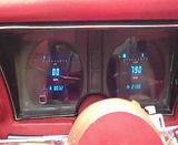
Lost my glove box with the vintage air so it was a good place to mount the DD control.

Lost my glove box with the vintage air so it was a good place to mount the DD control.


 05-17-2014, 08:24 PM
#16
Racer

Member Since: Feb 2010
Location: Leominster MA
Posts: 494
Likes: 0
Received 0 Likes
on
0 Posts
I did this same install this past winter in my 75. Used the GPS module for my speedo. Real easy install with the wiring diagrams. Love the look and function. Well done with your pictures. This will certainly be a help to many. (suggest a sticky on this one)
05-18-2014, 12:56 AM
#17
Burning Brakes
I just want to come over and set the clock to different times, that part was cool. I'm pretty happy with my speedhut gauges but they don't do what yours do.

