
wiring help
 09-23-2014, 08:01 PM
#1
Melting Slicks

Thread Starter

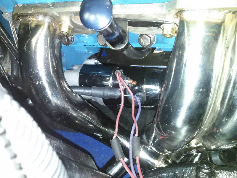
I have several different wiring diagrams, but I cannot seem to identify these wires. They are coming off the starter harness where the extension plugs in.
For the starter itself, I have two red and the battery cable on one lug
of the starter (top post) and the purple one on the small spade connecter. That should be all I need to the starter, the black grounds to frame?
This is on a 78, l48, th350 with factory air. Using an after market mini starter.
For the starter itself, I have two red and the battery cable on one lug
of the starter (top post) and the purple one on the small spade connecter. That should be all I need to the starter, the black grounds to frame?
This is on a 78, l48, th350 with factory air. Using an after market mini starter.
 09-23-2014, 09:56 PM
#2
Melting Slicks
those look like the feed wires for the aux. electric fan on the L82 / AC cars.
09-24-2014, 11:40 AM
#3
Melting Slicks
Thread Starter
are you referring to the plastic connector? I don't see that on any of the diagrams, any idea if either of them is a switched hot? It looks like the other two are for the anti-theft switch? But I cant find where the plug into. I havnt found much on the anti theft system on this car. Will the entire car disable if it isn't all hooked up?
09-24-2014, 12:15 PM
#4
Le Mans Master

 09-24-2014, 04:59 PM
#5
Team Owner


Member Since: Jun 2000
Location: Southbound
Posts: 38,928
Likes: 0
Received 1,469 Likes
on
1,248 Posts
Cruise-In II Veteran

If memory serves, the electric fans came out on the 79 L-82s.

 09-25-2014, 07:18 PM
#8
Race Director


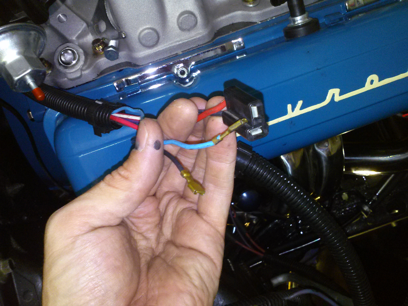
Please post another photo so I can see all the wires clearly...you and is blocking what I need to see. Also...I would like to see the connector from your starer extension harness.
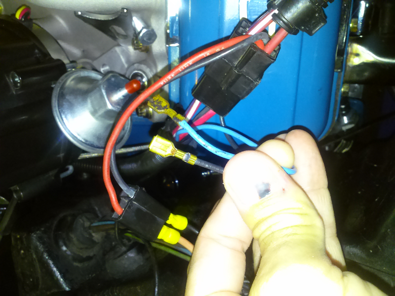
I am seeing white wire and can not tell what color the wire is that is behind the red wire that your two finger are touching.
Also writing what color are in a each connector is helpful due to sometimes photos can not show up the color correctly due to a flash. Sometimes the color can get washed out.
DUB
09-25-2014, 07:41 PM
#9
Melting Slicks
Thread Starter
DUB, thanks yet again. I'll get another photo tomorrow (away right now). For some reason some of these aren't showing up on my diagram. The black one is there but it doesn't say where it grounds.
09-26-2014, 08:53 AM
#10
Melting Slicks
Thread Starter
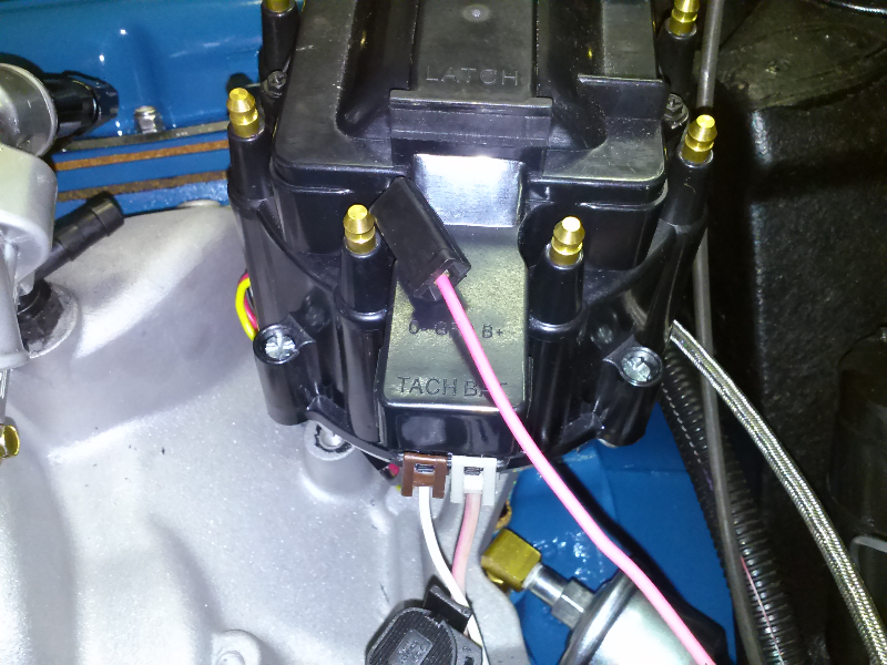
Wires are red and black to this plug
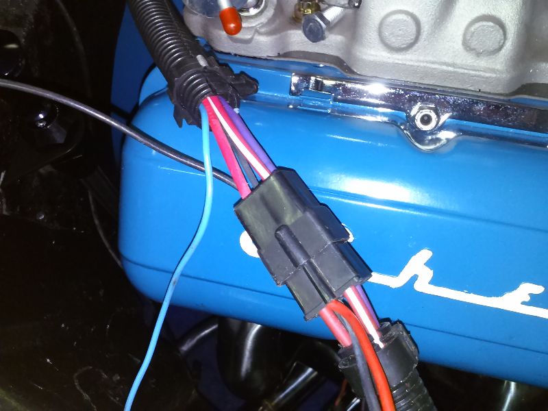
Better view of extension plug
These wires are Lt Blue and Black. Hood anti-theft I believe, but cannot find where the plug into
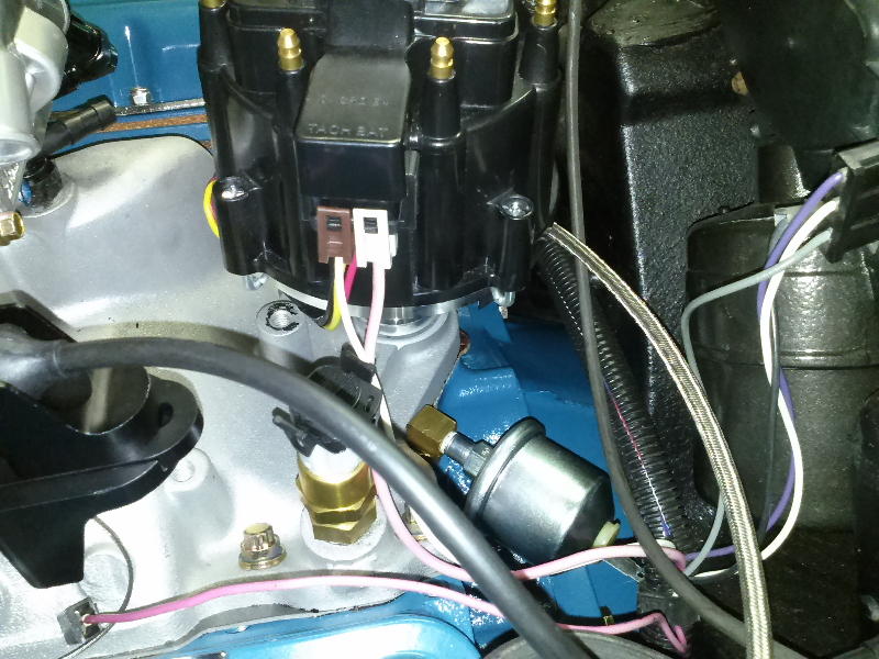
what I believe are the correct wires for the HEI, one is actually more pink looking than brown. The other is white. Diagrams all show brown, but the only brown wire I have in that area is the brake pressure switch, and that one is obvious.
I also have this pink or red wire that I "believe" to be the oil pressure wire.
Last edited by Vette-kid; 09-26-2014 at 09:01 AM.
09-26-2014, 06:54 PM
#11
Race Director
Thanks for the photos. Much better. I will get back but must comment on what I see.
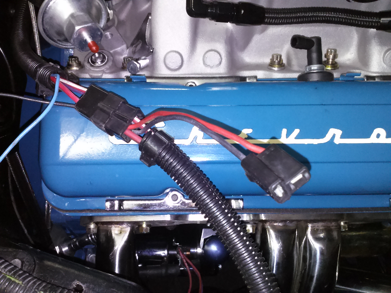
ALSO...DO NOT ROUTE the wires to your starter the way you have them routed.. BAD IDEA. ****HEAT!!!!***** Do not route the wires through the header like you have them.
After being connected like you have them. The wiring goes down the firewall...behind the passenger head...and then will go towards the starter. Keeping these wires tight to the block as possible is what you want...so they are as far from heat as possible. REMEMBER..the RED wire is the wire that powers your fuse panels and all components. ALSO...on some cars that have headers where I have concern. I go an buy the silver sleeve material form O'Reilly made by DEI and slide the wires through a section of it to protect these wires from the radiant heat.
DUB
09-27-2014, 05:18 PM
#13
Race Director
The RED and BLACK wire two terminal connector connects to your Air Conditioning harness. It is exclusive to a 1978. 1977's do not have it...and 1979's use a six terminal connector.
The RED wire from your starter harness goes to the 5 terminal high speed fan blower relay. The black wire is to ground your blower motor.
It is in the wiring schematic. Look at the wiring schematic for your A/C and you will see where the A/C harness connects to the 2 terminal connector pigtail.
Just to let you know...not knowing if you know...but in time the 4 terminal connector that is at the end of your starter harness will fail. It may take a while...but it will. Especially the terminal for the red wire. It supplies power to your car...and it carries so much of a load...that IF the terminals are not CLEAN and really maintaining really good contact. Resistance will being in this connection of these two connectors and it will get hot and melt the plastic. Due to this connection being so IMPORTANT....and GM did not begin using water tight connections at the time of manufacture. They were not made yet. That I would use a electrical anti-corrosive/moisture compound and inject it into these two connectors to keep dust and moisture of it it...IF you plan on using it.
Normally...I cut the wires and solder them together and use shrink wrap to keep things right.
DUB
09-27-2014, 09:26 PM
#14
Melting Slicks
Thread Starter
ok, I see it on the schematic now, kind of have to know its AC to know where to look 
Whats odd, is it isn't in the Chevrolet diagram. I do see it on my Lectric Limited and Classic Car Wiring ones.
I did a quick look at the car and I don't see it coming off the harness. Where approximately should this be located? I'm not running AC right now, but if this goes to the blower, it might be nice to have the fan operating.
I hadn't heard that about these connectors. Is it worth it to have a connector in there? I can put a weather-pac in its place, or just tie them together as you suggest.
Last edited by Vette-kid; 09-27-2014 at 09:28 PM.
09-27-2014, 10:35 PM
#15
Race Director
I did a quick look at the car and I don't see it coming off the harness. Where approximately should this be located? I'm not running AC right now, but if this goes to the blower, it might be nice to have the fan operating.
I hadn't heard that about these connectors. Is it worth it to have a connector in there? I can put a weather-pac in its place, or just tie them together as you suggest.
GM started using this connector and starter harness in 1978...and stopped in 1982. ALL of the years before that...did not have it. It was used for speed of assembly...and that is it. BECAUSE there is NO benefit to have it there.
The problem in using a 'weather-pac' style connector is getting one with terminals large enough to carry the load. Just adding in a connector does not cut it. The terminals need to be large enough to be able to handle the current.
AND to prove my point. In the bulkhead connector that attaches to your fuse block on the firewall side....the terminal that carries the power to your fuse panel...is the is the largest one in the terminal lock. Which is why I solder them when I have issues with one at the shop.
DUB
09-27-2014, 10:58 PM
#16
Melting Slicks
Thread Starter
This connector for the RED and BLACK wires is in the harness coming out of the firewall for the AC.....NOT the main engine harness. The A/C harness comes out of the firewall right beside the area where your VACUUM HARNESS comes out...which is behind the passenger valve cover area.
GM started using this connector and starter harness in 1978...and stopped in 1982. ALL of the years before that...did not have it. It was used for speed of assembly...and that is it. BECAUSE there is NO benefit to have it there.
The problem in using a 'weather-pac' style connector is getting one with terminals large enough to carry the load. Just adding in a connector does not cut it. The terminals need to be large enough to be able to handle the current.
AND to prove my point. In the bulkhead connector that attaches to your fuse block on the firewall side....the terminal that carries the power to your fuse panel...is the is the largest one in the terminal lock. Which is why I solder them when I have issues with one at the shop.
DUB
Thanks for the info, Ill look for it some more tomorrow. I looked around the harness where the connector for the compressor is and didn't see it there, but I didn't follow it all the way back to the firewall. At some point, someone cut a lot of wires, so it wouldn't surprise me if its missing.
09-28-2014, 11:13 AM
#17
Melting Slicks
Thread Starter
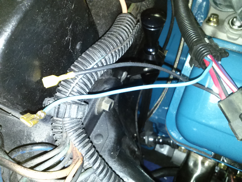
Ok, found em. As I suspected, the connector is gone. Here is what I've found. Not sure why they cut it, the wires are in fairly good condition...not brittle or worn through insulation.
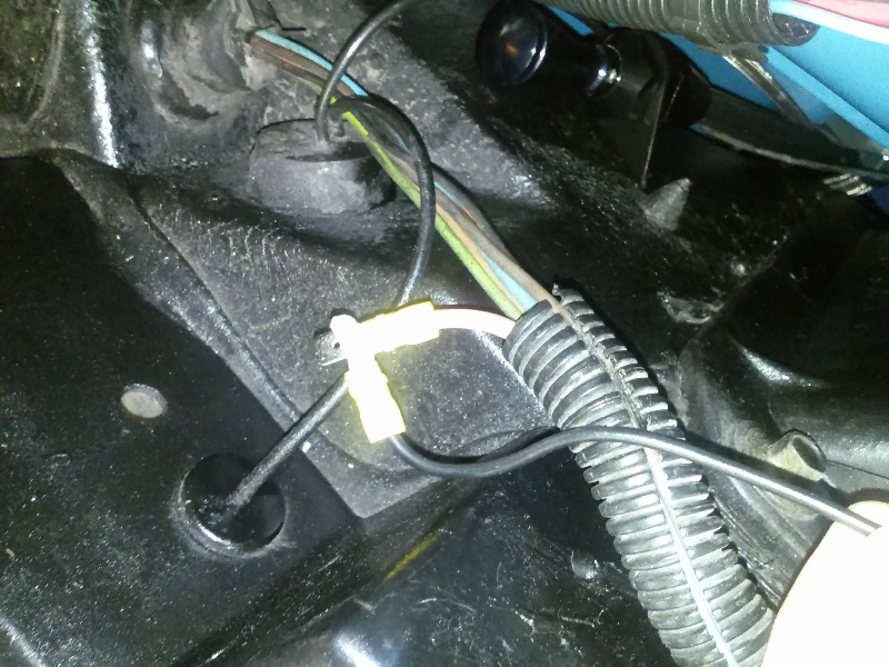
Black wire goes here
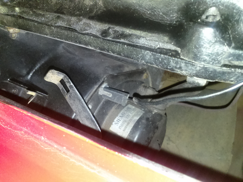
Now to find these two. Where should the anti theft switch be?
Black wire goes here
Now to find these two. Where should the anti theft switch be?
 09-28-2014, 06:26 PM
#19
Race Director
Vette-kid,
You did VERIFY that the wire that BOTH wires that you found coming out of your split loom are going to where they need to go. SO..like I wrote...the wire that you connected to the RED wire in your pigtail connector is going to your blower relay...CORRECT??? And the other is the ground for the blower motor itself....CORRECT????
The blue and black wires SHOULD be for your alarm switch for under the hood...BUT CHECK IT WITH AN OHMMETER and using your wiring diagram...you can verify this is correct. You can check continuity. IF they are correct...MAKE SURE that you put them in the switch THE CORRECT WAY. ( if you are actually going to use it) When you look at the switch there should be a very small hole in the terminal. When you go and slide the terminal onto it. Make sure that you put the terminal on so if you have to take it off...you can go inside that small hole and press on the lock that is a part of the terminal itself with a sharp pointed pick tool. SO...basically...when you put the wires on...you want to be able to see the hole in the spade terminal of the switch....and NOT the other way around. This ALSO goes for all other switches of this design that the car has on it.
DUB
09-28-2014, 08:05 PM
#20
Melting Slicks
Thread Starter
Dub, yes I verified those wires go where they are supposed to...the relay (top of firewall, pass side) and ground on the blower itself.
I don't have any of the switches for the alarm, so I don't plan on using it right now, as long as that wont cause any problems.
Thanks to 'finallygotit' for posting the pic so I know what im looking for. Definitely don't have any of those.
I don't have any of the switches for the alarm, so I don't plan on using it right now, as long as that wont cause any problems.
Thanks to 'finallygotit' for posting the pic so I know what im looking for. Definitely don't have any of those.