
Vacuum diagram question
 01-27-2015, 10:47 PM
#1


I just installed all 24 new vacuum lines as shown in the attached PDF diagram. You will see that the wiper door solenoid under the dash has vacuum hose 4 and 7 going into it. The solenoid also has another connector that looks identical to the other 2. It looks like a dial or a filter in the attached diagram. What ever it is, mine is missing. If I were to guess I would say it was a missing filter. If so, do I have to buy a new wiper door solenoid or can I get a filter that will work for this. If it is not a filter what could this 3rd inlet possibly be?
Your help as always is greatly appreciated.
Your help as always is greatly appreciated.
 01-30-2015, 08:56 PM
#2
LMK
01-31-2015, 12:55 AM
#3
Burning Brakes


Is this a one way vent? Since you called it a vent I assume air comes out but not back in. Is this correct? I have several one way filters I might be able to use on this.
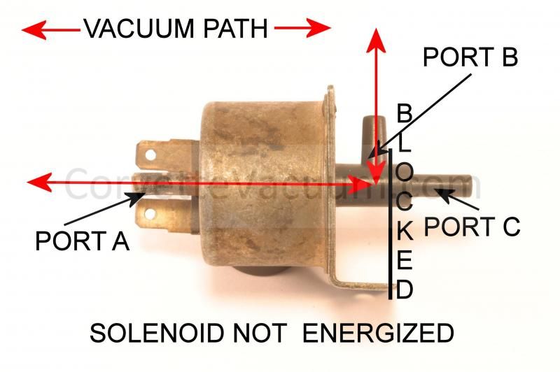
The activation of the wiper switch determines the vacuum path in the solenoid, as in the following diagrams.

You can see that control vacuum flows through the solenoid in the above picture. The relay top vacuum chamber is sealed to hold it.

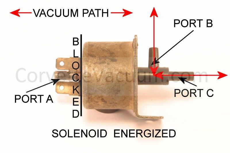
This picture shows the control vacuum blocked at the inlet port, and allows the vacuum that was in the balance of the hose to be lost to atmosphere, or vented so to speak. The bottom line is there is no need for one way filters or check valves.
Last edited by Dave J; 01-31-2015 at 01:01 AM. Reason: added picture
02-04-2015, 10:47 PM
#4
The vent you refer to at the end of the solenoid is designed to allow atmospheric pressure to enter the control circuit of the wiper door system (port c). The term VENT is mostly a misnomer, in that the operation of the control circuit relies more on the principle of vacuum evacuation, or simply replacing the evacuated hose with atmospheric pressure. I know, lots of words, but it's the application of atmospheric pressure that does the moving in our systems.
The activation of the wiper switch determines the vacuum path in the solenoid, as in the following diagrams.
You can see that control vacuum flows through the solenoid in the above picture. The relay top vacuum chamber is sealed to hold it.
This picture shows the control vacuum blocked at the inlet port, and allows the vacuum that was in the balance of the hose to be lost to atmosphere, or vented so to speak. The bottom line is there is no need for one way filters or check valves.