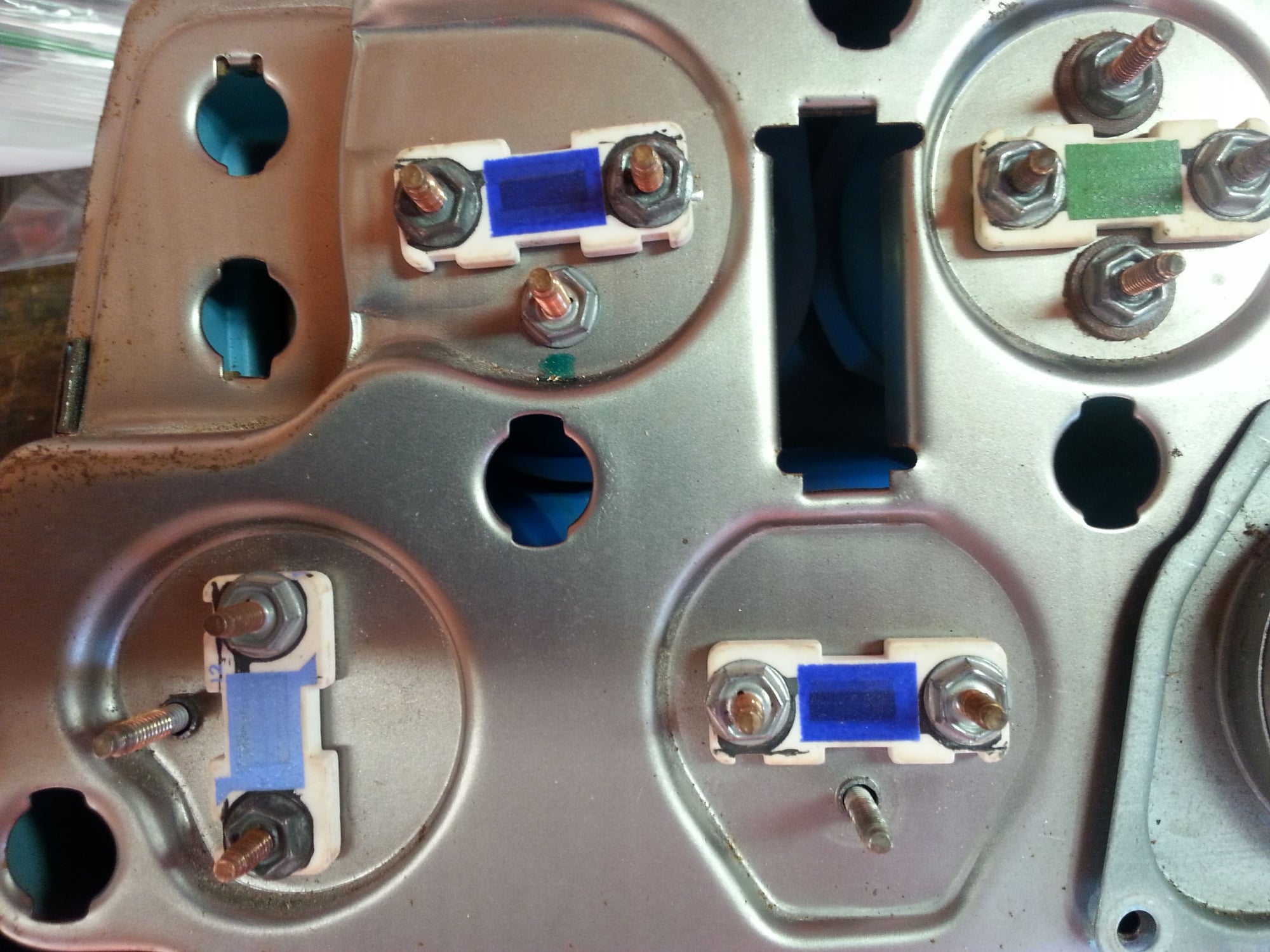
1977 Printed circuit board
#1
Instructor


Thread Starter
Are there nuts between the resistors and the printed circuit?
Are there any other insulators besides the phenolic washers on the water temp posts?
Is the metal bezel grounded?
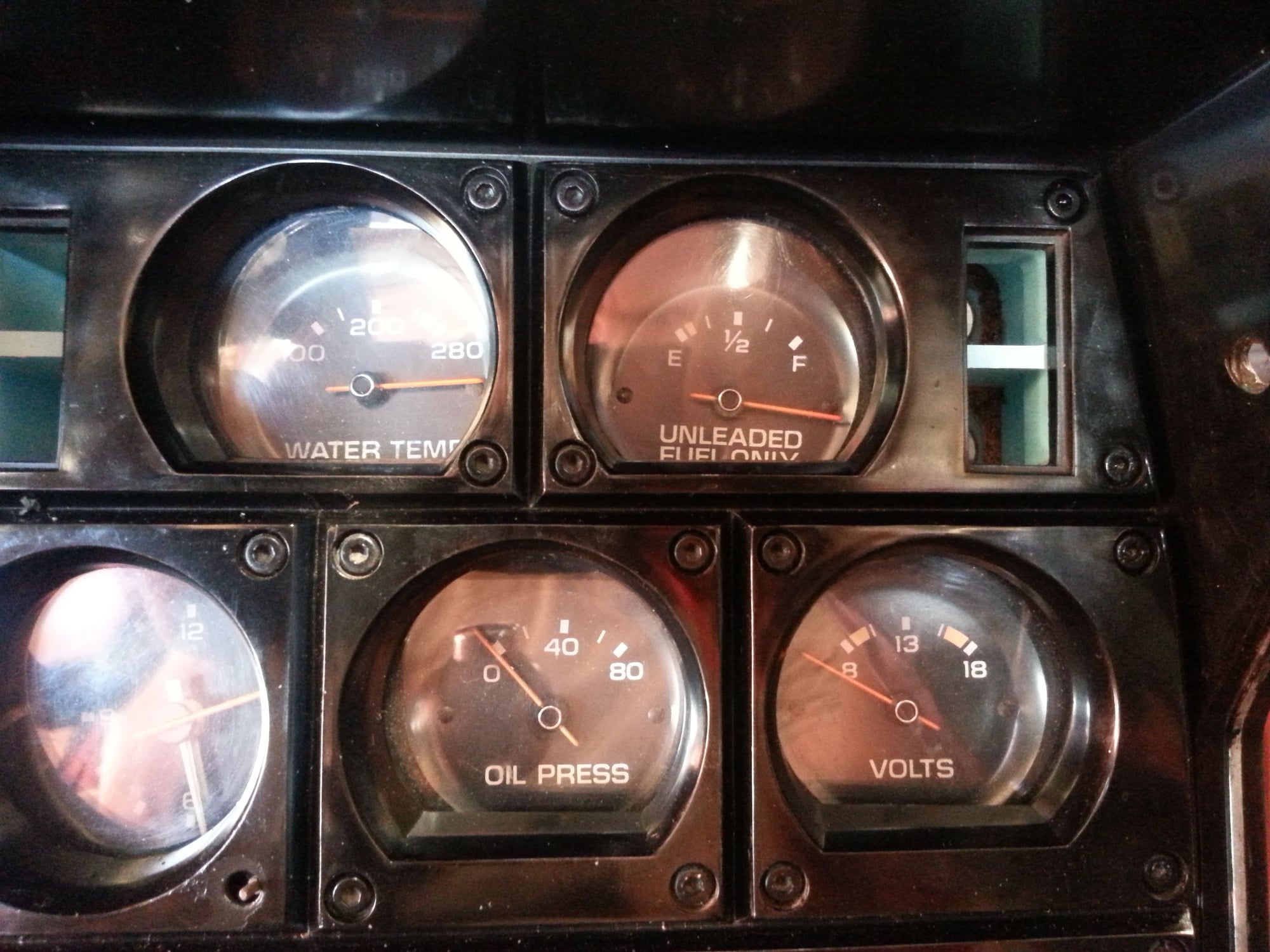
Im having a problem with all my gauges. They all have power but no signal. Ive verified all the grounds and sending wires at the rear connector. Any thoughts? Thanks guys.
Are there any other insulators besides the phenolic washers on the water temp posts?
Is the metal bezel grounded?
Im having a problem with all my gauges. They all have power but no signal. Ive verified all the grounds and sending wires at the rear connector. Any thoughts? Thanks guys.
Last edited by Jayson77; 03-31-2015 at 07:40 PM.
#3
I realize this is not a direct answer but have you ever looked through here?
http://willcoxcorvette.com/repairand...34adb6b7640519
Ernie at Willcox will know the answer. Good luck with it. mike...
http://willcoxcorvette.com/repairand...34adb6b7640519
Ernie at Willcox will know the answer. Good luck with it. mike...
#4
Instructor


Thread Starter
I realize this is not a direct answer but have you ever looked through here?
http://willcoxcorvette.com/repairand...34adb6b7640519
Ernie at Willcox will know the answer.
Good luck with it. mike...
http://willcoxcorvette.com/repairand...34adb6b7640519
Ernie at Willcox will know the answer.
Good luck with it. mike...
#6
Instructor


Thread Starter
Is there a trick to removing the fuel level sendign unit wire from the post on top of the tank? I'd like to ohm the wire from the post to the gauge. Thanks guys.
#7
Instructor


Thread Starter
I figured out that when I grounded the metal bezel my oil pressure guage and lights work. I temporarily grounded it using a jumper with alligator clips.
I realize the additional ground isnt from the factory.
Anyone have a clue what the problem is?
I realize the additional ground isnt from the factory.
Anyone have a clue what the problem is?


