
700r4 Lockup in 4th Gear wiring HELP!?!
 08-01-2015, 02:02 PM
#1

There are a lot of threads on here about 700r4's in C3s but I'm still a bit confused. I have it installed already in my 78 and I just finished rebuilding the valve body to make sure I don't have a stuck TV valve.
I noticed I have my lockup solenoid wiring goes to a 4 connector plug on the outside driver's side of the case. Do I need to have a 12v power source to have lockup? Where is the 12v source supposed to come from? My tranny is a 1992 year model.
I seen there are kits with a toggle switch, I don't want that. I want the torque converter to just lockup in 4th gear and kick off automatically. I am sure I will need a wiring kit for the internal of the tranny. But I'm just confused about this outside plug and what has to be connected to that.
Thanks!
Last edited by Matty Gritt; 08-01-2015 at 02:26 PM.
 08-01-2015, 02:22 PM
#2

I have the TCI kit. Requires a keyed 12v, ground, and a vacume connection for the switch.
Someone can confirm but I bekeuve all the lock up kits require a keyed 12v source.
Not all have the vacume switch. I only went with the TCI kit as Mad Dog Trans prefers them.
Someone can confirm but I bekeuve all the lock up kits require a keyed 12v source.
Not all have the vacume switch. I only went with the TCI kit as Mad Dog Trans prefers them.
08-01-2015, 02:26 PM
#3
I have the TCI kit. Requires a keyed 12v, ground, and a vacume connection for the switch.
Someone can confirm but I bekeuve all the lock up kits require a keyed 12v source.
Not all have the vacume switch. I only went with the TCI kit as Mad Dog Trans prefers them.
Someone can confirm but I bekeuve all the lock up kits require a keyed 12v source.
Not all have the vacume switch. I only went with the TCI kit as Mad Dog Trans prefers them.
I will look up the TCI kit. Have you had any major problems with yours?
08-01-2015, 02:28 PM
#4
Melting Slicks


Member Since: Apr 2009
Location: Great Plains Iowa
Posts: 2,632
Likes: 0
Received 114 Likes
on
108 Posts
There are a lot of threads on here about 700r4's in C3s but I'm still a bit confused. I have it installed already in my 78 and I just finished rebuilding the valve body to make sure I don't have a stuck TV valve.
I noticed I have my lockup solenoid wiring goes to a 4 connector plug on the outside driver's side of the case. Do I need to have a 12v power source to have lockup? Where is the 12v source supposed to come from?
I seen there are kits with a toggle switch, I don't want that. I want the torque converter to just lockup in 4th gear and kick off automatically. I am sure I will need a wiring kit for the internal of the tranny. But I'm just confused about this outside plug and what has to be connected to that.
Thanks!
The 12 volts can come from the IGN terminal on your fuse block or any other source of 12 volts. In my case I'm using a terminal on my horn relay to supply the 12 volts and a 15 psi pressure switch screwed into the 4th servo pressure tap (right behind the servo) to send that 12 volts to my solenoid. It automatically locks when it shifts into 4th and unlocks when it downshifts into 3rd.
08-01-2015, 02:34 PM
#5
Haven't driven it yet so I hope it's good. No concern with the 12 volt. Vacume should be good. If not I'll go to a port on my manifold connection.
08-01-2015, 02:42 PM
#6
The 12 volts can come from the IGN terminal on your fuse block or any other source of 12 volts. In my case I'm using a terminal on my horn relay to supply the 12 volts and a 15 psi pressure switch screwed into the 4th servo pressure tap (right behind the servo) to send that 12 volts to my solenoid. It automatically locks when it shifts into 4th and unlocks when it downshifts into 3rd.
08-01-2015, 03:55 PM
#7
Le Mans Master

There should already be a pressure switch on the valve body. That switch will be NO (normally open). The switch has one terminal, make sure the wire from the lock up solenoid ground goes to the terminal on the pressure switch. The positive wire from the solenoid will go to the case connector and be fed 12v from whatever source you choose. If your car has cruise control, there will be a switch on the brake pedal that activates the brake lights and has another set of wires on it to de-activate the cruise when the pedal is pushed. Use the wire on the cruise circuit that has voltage when the pedal is up and no voltage when the pedal is pushed, this way your lock up torque converter will unlock when you push the brake pedal. Run that wire to the case connector on the trans that feeds the solenoid. The plug for the case connector is on e-bay and is expensive, $38. You can get a 1 wire case connector for around $10 and not use the factory style connector.
http://www.ebay.com/itm/700-R4-4L60-2004R-HP-4th-gear-only-Lock-up-Kit-/250782490166?hash=item3a63cd1e36&vxp=mtr
You could also get this lock up control that is speed adjustable and is plug-n-play, but a little more money.
http://www.ebay.com/itm/B-M-Gm-Torque-Converter-Dash-Mounted-Lockup-Control-TH-700-200-200-4R-350-4L60-/141608982622?hash=item20f88d985e&vxp=mtrYou can find this one at Advance Auto online and save $50 with coupon code TRT30.
Last edited by '75; 08-01-2015 at 03:59 PM.
08-01-2015, 03:56 PM
#8
Race Director

Member Since: Apr 2007
Location: South Western Ontario
Posts: 11,061
Received 845 Likes
on
721 Posts

There are basically 4 ways to control the TCC.
1. By speed. This is what the B&M kit does. Works good but it doesn't unlock when you want to accelerate.
2. By vacuum. This is what a vacuum switch does, and is the main part of the TCI kit. It unlocks the converter when you try to accelerate which is exactly what you want to have happen. The downside of just a vacuum switch is that it can lock the converter at lower speeds and lug the engine.
3. By pressure. Locks the converter in one combination of 2-4th or 3-4th or 4th gear. The only way to unlock the converter when you want to accelerate is by kicking down the transmission to a gear where it doesn't lock. I'm not a fan of locking it when you switch into 4th gear and completely opposed to suggestion on how to lock it in 2-4th or 3-4th gear. The result of a 4th gear automatic lockup will be that you manually shift in and out of 4th gear instead of manually locking the converter via a toggle switch. This is the second part of the TCI kit, a pressure switch so it only locks in 4th gear.
4. Manually. You lock and unlock it when you want.
Then, there are 100's of different ways to combine the above.
For example, the TCI kit combines a 4th gear pressure switch and the vacuum switch to only lock in 4th gear when the vacuum is high. This is a decent solution but you may find you still lug the engine in the bottom of 4th gear when low rpm's and lockup occur. Then, you still end up manually shifting down to 3rd to eliminate the lockup.
As another example, you could combine a vacuum switch and the B&M kit to only lock the TCC with high vacuum above a certain speed. This does a decent job emulating how GM fuel injected systems control the TCC. You don't lock the converter at low speed and low rpm's. You also get the converter unlocking when you step into the gas to accelerate.
Last edited by lionelhutz; 08-01-2015 at 04:04 PM.
08-01-2015, 04:32 PM
#10
Nam Labrat


Member Since: Sep 2013
Location: New Orleans Loo-z-anna
Posts: 33,899
Received 4,179 Likes
on
2,739 Posts

FYI.........The simplest wiring method is----a wire from the fuse block that has 12 volts ONLY when the ignition is in the ON/RUN position which connects to the transmission case connector at one of the terminals that supplies the solenoid with 12 volts. The other connector terminals are not used if your car is not pre-wired for "Overdrive".
However....other items are necessary to prevent damage to the transmission or to prevent engine stalling.
The lock-up solenoid needs to UNLOCK when the accelerator is floored....unlocking prevents damage to the internal parts of the transmission (the vacuum-operated electric switch accomplishes this and it is adjustable so that you can "set" it for your type of driving. You can connect the vacuum to manifold vacuum/the easiest method.
Using a combination "cruise control/brake light switch" dis-engages the lock-up solenoid when you apply the brakes----so that the engine doesn't kill when the brakes are applied hard/sudden stops. The combination switch accomplishes this BUT it is not entirely necessary.
An easy-to-reach "ON/OFF" switch that can be wired into the basic lock-up circuit. It is the same thing as the "Engage/Dis-engage" button on the steering column shift handle of SUVs. (If you are driving on mountain roads, you would not want the lock-up circuit constantly up-shifting/down-shifting around every curve or steep incline.......you want to be able to turn the lock-up circuit OFF until you are no longer on curvey/steep inclines)
I hope the above makes things easier to understand.
Last edited by doorgunner; 08-01-2015 at 04:41 PM.
08-01-2015, 04:59 PM
#11
There should already be a pressure switch on the valve body. That switch will be NO (normally open). The switch has one terminal, make sure the wire from the lock up solenoid ground goes to the terminal on the pressure switch. The positive wire from the solenoid will go to the case connector and be fed 12v from whatever source you choose. If your car has cruise control, there will be a switch on the brake pedal that activates the brake lights and has another set of wires on it to de-activate the cruise when the pedal is pushed. Use the wire on the cruise circuit that has voltage when the pedal is up and no voltage when the pedal is pushed, this way your lock up torque converter will unlock when you push the brake pedal. Run that wire to the case connector on the trans that feeds the solenoid. The plug for the case connector is on e-bay and is expensive, $38. You can get a 1 wire case connector for around $10 and not use the factory style connector.
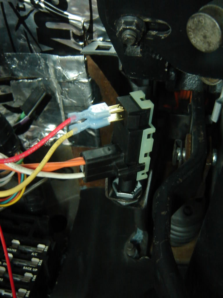
This is EXACTLY what my valve body looks like in the case...

So would these be good steps to take?
- 12v power will go from the red wire on the solenoid to the 12v source... which you recommend is my cruise control/brake light switch, not my ignition?
- The black wire runs to the case plug connector but it also runs to the temperature reader(?) then piggybacks to the pressure switch. I highlighted this with a blue arrow in the picture. What should I do there?
- The black wire running to the plug connector, does that feed out to any ground outside the transmission? Could I just ground it to the frame?
- Is the tan wire doing anything? What does that control?
FYI.........The simplest wiring method is----a wire from the fuse block that has 12 volts ONLY when the ignition is in the ON/RUN position which connects to the transmission case connector at one of the terminals that supplies the solenoid with 12 volts. The other connector terminals are not used if your car is not pre-wired for "Overdrive".
However....other items are necessary to prevent damage to the transmission or to prevent engine stalling.
The lock-up solenoid needs to UNLOCK when the accelerator is floored....unlocking prevents damage to the internal parts of the transmission (the vacuum-operated electric switch accomplishes this and it is adjustable so that you can "set" it for your type of driving. You can connect the vacuum to manifold vacuum/the easiest method.
Using a combination "cruise control/brake light switch" dis-engages the lock-up solenoid when you apply the brakes----so that the engine doesn't kill when the brakes are applied hard/sudden stops. The combination switch accomplishes this BUT it is not entirely necessary.
An easy-to-reach "ON/OFF" switch that can be wired into the basic lock-up circuit. It is the same thing as the "Engage/Dis-engage" button on the steering column shift handle of SUVs. (If you are driving on mountain roads, you would not want the lock-up circuit constantly up-shifting/down-shifting around every curve or steep incline.......you want to be able to turn the lock-up circuit OFF until you are no longer on curvey/steep inclines)
I hope the above makes things easier to understand.
However....other items are necessary to prevent damage to the transmission or to prevent engine stalling.
The lock-up solenoid needs to UNLOCK when the accelerator is floored....unlocking prevents damage to the internal parts of the transmission (the vacuum-operated electric switch accomplishes this and it is adjustable so that you can "set" it for your type of driving. You can connect the vacuum to manifold vacuum/the easiest method.
Using a combination "cruise control/brake light switch" dis-engages the lock-up solenoid when you apply the brakes----so that the engine doesn't kill when the brakes are applied hard/sudden stops. The combination switch accomplishes this BUT it is not entirely necessary.
An easy-to-reach "ON/OFF" switch that can be wired into the basic lock-up circuit. It is the same thing as the "Engage/Dis-engage" button on the steering column shift handle of SUVs. (If you are driving on mountain roads, you would not want the lock-up circuit constantly up-shifting/down-shifting around every curve or steep incline.......you want to be able to turn the lock-up circuit OFF until you are no longer on curvey/steep inclines)
I hope the above makes things easier to understand.
Last edited by Matty Gritt; 08-01-2015 at 05:02 PM.
08-01-2015, 05:20 PM
#12
Nam Labrat
Member Since: Sep 2013
Location: New Orleans Loo-z-anna
Posts: 33,899
Received 4,179 Likes
on
2,739 Posts
Wow thank you, that's some great info!! I don't really even need a wiring kit? So if I'm understanding this correctly... bear with me...
This is EXACTLY what my valve body looks like in the case...
So would these be good steps to take?
Thanks for the post as well, it does clear some things up. Having the 12v source come from my brake switch seems to be the nicest feature. I like the idea of when I hit the brake it disengages the lockup. So going to my plug connector, I would only have 1 wire coming from that and that is my 12v source wire? No ground wire coming out of that?
This is EXACTLY what my valve body looks like in the case...
So would these be good steps to take?
- 12v power will go from the red wire on the solenoid to the 12v source... which you recommend is my cruise control/brake light switch, not my ignition?
- The black wire runs to the case plug connector but it also runs to the temperature reader(?) then piggybacks to the pressure switch. I highlighted this with a blue arrow in the picture. What should I do there?
- The black wire running to the plug connector, does that feed out to any ground outside the transmission? Could I just ground it to the frame?
- Is the tan wire doing anything? What does that control?
Thanks for the post as well, it does clear some things up. Having the 12v source come from my brake switch seems to be the nicest feature. I like the idea of when I hit the brake it disengages the lockup. So going to my plug connector, I would only have 1 wire coming from that and that is my 12v source wire? No ground wire coming out of that?
The red wire inside the transmission connects to a labeled terminal on the transmission case connector (A or B or C or D)....determine which external terminal the red wire is connected to------then-----connect your 12 volt source that leaves the brake combination switch to the correct case terminal.
Determine which terminal the valve body ground wire is connected to-----then---fabricate a ground wire that will connect to the correct external terminal on the case connector to a clean location on the frame near the case connector.
I don't think you should do anything with the tan wire----it may be only for the gm computer/un-necessary on your car.
Other members can correct me if I mis-stated something (there are several ways to re-wire the solenoid/valve body/pressure switches/cold temperature control switch)
(The cold temperature control switch prevents the transmission from "locking-up" until the transmission reaches operating temperature....which is good for owners who drive daily in cold climates.....the temperature switch can be bypassed, but that's another can-of-worms)
(My 700R4 transmission ALSO has a 3rd gear lock-up pressure switch/I manually put the shifter into 3rd gear when driving in-town to prevent the transmission from shifting too much below 60 MPH)
Last edited by doorgunner; 08-01-2015 at 05:27 PM.
 08-01-2015, 05:33 PM
#14
Race Director
Member Since: Apr 2007
Location: South Western Ontario
Posts: 11,061
Received 845 Likes
on
721 Posts
From what I've seen, the temperature switch on EFI applications appears to ground the solenoid which bypasses the PCM control. Possibly to force lock the converter when the temperature is high so the converter isn't adding even more heat to the transmission.
08-01-2015, 05:34 PM
#15
Nam Labrat
Member Since: Sep 2013
Location: New Orleans Loo-z-anna
Posts: 33,899
Received 4,179 Likes
on
2,739 Posts

Will that combination switch fit on a '68 with manual brakes/If so, what year/make/model is the switch original designed to fit (so I can order one)?
08-01-2015, 05:42 PM
#16
Burning Brakes

The 68 brake switch looks to be completely different, this thread might be usefull to you? https://www.corvetteforum.com/forums...ht-switch.html
link to switch : https://www.rockauto.com/catalog/mor...id=486&jpid=12
Nick
link to switch : https://www.rockauto.com/catalog/mor...id=486&jpid=12
Nick
Last edited by dembo; 08-01-2015 at 05:51 PM.
08-01-2015, 05:47 PM
#17
Race Director
Member Since: Apr 2007
Location: South Western Ontario
Posts: 11,061
Received 845 Likes
on
721 Posts
On a late model EFI transmission, my guess would be that if you apply power to terminal A of the connector and ground to terminal D that the TCC will lock in 3rd and 4th gear. The typical EFI applications applied power to terminal A through a brake pedal switch. Then, the PCM grounded terminal D.
Terminal B came from a pressure switch that indicated the transmission was in 4th gear. The typical EFI diagram shows the pressure switch wired between terminals B and D, or the black and tan wires. This was used because the PCM had different 3rd gear and 4th gear lockup settings and the switch would tell the PCM that the transmission was is 4th gear.
It appears from your wiring that you could apply power to terminal A or the red wire. This would apply 12V to the solenoid.
Then, when you ground terminal D or the black wire the TCC will lock in 3rd gear or 4th gear.
You could also ground terminal B or the tan wire and the TCC will only lock in 4th gear.
As a minimum, I'd put a vacuum switch between either of those terminals and ground to lock the TCC. I think you will be disappointed with any wiring that permanently locks the TCC in 3-4th or 4th gear. I know I was, which is one of the reasons I'm now using a 4L60e instead which allows full control over the shifting and lockup.
08-01-2015, 06:11 PM
#18
Race Director
Member Since: Apr 2007
Location: South Western Ontario
Posts: 11,061
Received 845 Likes
on
721 Posts
Damn, I Think I reversed the switches looking at the diagram. Can you describe what you're seeing inside the transmission to ensure what you have.
I believe the black wire should go to terminal D of the connector, the TCC solenoid and the thermal switch.
The red wire should go to terminal A of the connector and the TCC solenoid.
The tan wire should go to terminal B or the connector, the other terminal of the thermal switch and the 4th gear pressure switch (the one you labelled with the blue arrow).
I believe you can apply power between terminals A and D with your stock configuration but that will lockup the converter in 3rd and 4th gear. I don't believe my previous comment about grounding terminal B or the tan wire to lockup only in 4th is valid.
08-01-2015, 06:13 PM
#19
I think you should leave the valve body wiring "as is". (You really don't need an internal wiring kit unless a previous owner has damaged/removed the existing wiring)
The red wire inside the transmission connects to a labeled terminal on the transmission case connector (A or B or C or D)....determine which external terminal the red wire is connected to------then-----connect your 12 volt source that leaves the brake combination switch to the correct case terminal.
Determine which terminal the valve body ground wire is connected to-----then---fabricate a ground wire that will connect to the correct external terminal on the case connector to a clean location on the frame near the case connector.
I don't think you should do anything with the tan wire----it may be only for the gm computer/un-necessary on your car.
Other members can correct me if I mis-stated something (there are several ways to re-wire the solenoid/valve body/pressure switches/cold temperature control switch)
(The cold temperature control switch prevents the transmission from "locking-up" until the transmission reaches operating temperature....which is good for owners who drive daily in cold climates.....the temperature switch can be bypassed, but that's another can-of-worms)
(My 700R4 transmission ALSO has a 3rd gear lock-up pressure switch/I manually put the shifter into 3rd gear when driving in-town to prevent the transmission from shifting too much below 60 MPH)
 So good to know I can do it all myself without a kit. So all I am going to have are two wires coming out of the plug. A power and a ground going to the corresponding spots in the transmission socket. Got it! You are seriously a life saver man, you made it very easy to understand!
Awesome thank you for the picture! I will be doing the same. How does yours run, have any problems? I only have a 350 that isn't trying to push any speed records.

