When you click on links to various merchants on this site and make a purchase, this can result in this site earning a commission. Affiliate programs and affiliations include, but are not limited to, the eBay Partner Network.
The ones in front are for the courtesy lights, the ones in the back are for the alarm. My car is not here and won't be for I don't know how long, or I would try to make sense of your situation and for that I apologize..... I will search my AIM and service repair manual and see if I can find something. Did you look at the fuse box and find anything labeled Alarm; I cannot remember seeing one on mine but it's been a while since I have looked. There may be an inline fuse in where the works are behind the pass seat. Here is something I just found:
No didn't find anything relating to alarm in the fuse box.
An interesting read that link you posted. Could it be possible that the orange wire in the jack compartment supplies power to the alarm system, am I reading it correctly?
Seeing the compartment light is not connected, would that mean the power is cut to the alarm system? Is that part of the circuit?
Last edited by Corvetteoz; 03-05-2016 at 08:48 AM.
Reason: Add
Hi,
I can't be any help with the alarm… but are the cut black and orange wires actually for the glove box light… it looks like the connectors have been cut off?
Regards,
Alan
Tried a test run of the alarm system today. Sadly I could not a get any pulse or any sign of even an alarm being on when I triggered the system. Where is the fuse for the alarm system?
I'm going to test the actuators on the doors and bonnet tomorrow. Could someone chime in exactly how I can test these with my multi-meter? I know how to test for continuity but exactly how to do it I'm not sure? Do I need the alarm turned on and exactly what wires do I need to test? Also which of the door actuators activate the alarm, the ones to the rear of the car or the ones at the front of the doors?
No didn't find anything relating to alarm in the fuse box.
An interesting read that link you posted. Could it be possible that the orange wire in the jack compartment supplies power to the alarm system, am I reading it correctly?
Seeing the compartment light is not connected, would that mean the power is cut to the alarm system? Is that part of the circuit?
Your statement above in bold made me laugh! I don't mean this in a bad way, but clearly, you are confused!!!
Using a multimeter to test for continuity simply tests for a complete and unbroken continuous electrical path from one point to another along one or more wires. Please post a pic of the multimeter you are using.
As I already told you, the orange and black wire in the jack compartment are for the rear center glove box compartment light; the orange wire does not supply the power to the alarm circuit. See Alan 71's pic for reference to this part.
Step one:
Let's start with the basics, we can start with the +12v side of the circuit.
The following items are all on the same circuit:
-front left and right footwell courtesy lights
-cigarette lighter
-clock
-rear compartment courtesy light
-rear center glove box compartment light
-alarm system
This circuit is "hot" at all times, meaning it is never turned off through the ignition key switch.
The fuse for this circuit is the 20a one under the flasher on the left hand side of the fuse box, it is marked: CLK LTR CTSY
Unplug the 3 wire connector from the alarm relay and the 2 wire connector from the alarm flasher, and put the alarm system in the "disarmed" state - the key switch in the rear panel is in the vertical position.
Make sure the loose orange glove box light wire in the jack compartment is not touching the loose black glove box light wire, or any other part of the car that is grounded.
If the fuse for this circuit was blown, replace it.
Does the new fuse blow right away, or is it okay, and do all the other items on the circuit list work?
I confuse myself sometimes too . But seriously I have never tested for continuity before so this is why I ask.
The front left and right courtesy lights and rear compartment courtesy light work as well as the cig lighter. Fuse is obviously ok then.
It almost seems as if there is no power to the alarm system at all. I might try and test if there is power going to the relay by putting the multimeter to Voltage and touching the red probe into the red wire plug on the relay and black probe to ground. Please let me know if I'm doing something wrong.
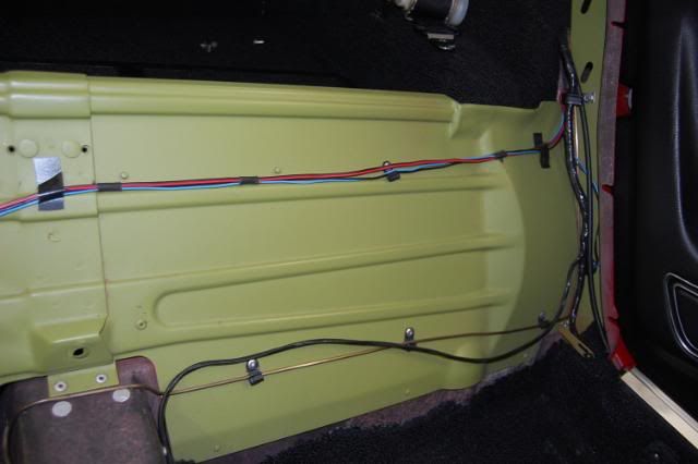
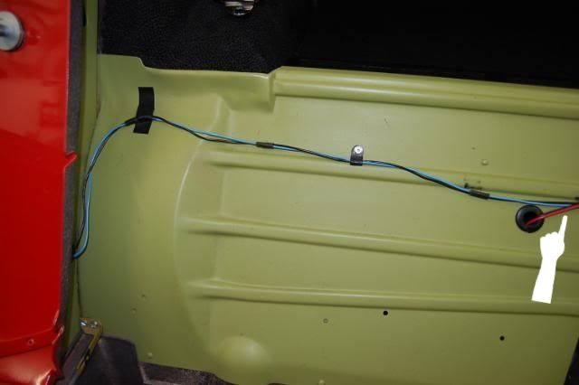
Looking at Alans pic of the centre compartment light, where exactly do those wires for the light plug into? As you can see from my above pic, I dont have any other wires or posts for them to plug into?
Last edited by Corvetteoz; 03-05-2016 at 06:43 PM.
Looking at Alans pic of the centre compartment light, where exactly do those wires for the light plug into? As you can see from my above pic, I dont have any other wires or posts for them to plug into
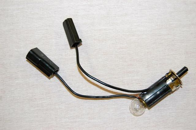
The loose orange and black wires in your jack compartment plug into the wires on this lamp and switch assembly:
This lamp and switch assembly wiring is accessible in the jack compartment. This assembly is installed on the passenger side of the rear glove box; the lamp shines through the white lens and the pin switch sticks up through the hole at the top in this pic:
Looking at the left side of this pic you posted, it actually looks like the wires for your lamp and switch assembly are plugged into each other; if that is the case, you need to unplug them, and connect the orange and black wires to them instead:
I am attempting to guide you through basic electrical circuit troubleshooting, which needs to be done in a logical, step by step, process of elimination. Doing it over the internet and not in person makes it harder, and I won't be able to help you very well unless you follow my instructions in the order I give them to you.
So far we have established that the fuse for the circuit is ok, since your courtesy lights and cigarette lighter work. After you connect the wires for the glove box light, see if the light and switch work. If they do, and the fuse does not blow, I still need you to do the following:
Put the alarm system in the "disarmed" state - the key switch in the rear panel should be in the vertical position, and then unplug the 3 terminal connector from the alarm relay and the 2 terminal connector from the alarm flasher.
Put your meter to the DC voltage setting. Since the battery is close by, put your black meter probe on the negative battery post, and your red meter probe into the 3 terminal alarm relay connector where the pink wire is; with the alarm system in the "disarmed" state, you should get no reading.
Now put the alarm key switch in the "armed" position - the key switch in the rear panel should be in the horizontal position, and measure once again with your meter at the same points as before. This time you should see +12v (or whatever your battery voltage is at).
This will establish if the wiring and alarm "arm/disarm" key switch are all in good working order for the +12v portion of the circuit.
My pic of the alarm devices and wiring and the factory schematic drawing again for reference:
Well what a pain to get in there to fix this problem.
First of all I had no globe in the compartment light and secondly the wire that was ground fell off so I was unable to see if the compartment even works. I removed the compartment light and repaired the ground wire which came off, luckily it just plugs into the side of the housing. After that I had to put some new plugs onto the connections of the light as two of them were stuffed. Once that was done I tested the wires to find a bit over 12 volts going to the compartment light.
After this I done what you said step by step and still didn't receive any power readings from where the pink wire enters the plug for the relay. I tried it with the alarm in the off position and on position. It just looks like there is no power going to the alarm at all. So if there is no power going to the relay what could be causing this?
Last edited by Corvetteoz; 03-06-2016 at 03:56 AM.
Reason: delete
Well what a pain to get in there to fix this problem.
First of all I had no globe in the compartment light and secondly the wire that was ground fell off so I was unable to see if the compartment even works. I removed the compartment light and repaired the ground wire which came off, luckily it just plugs into the side of the housing. After that I had to put some new plugs onto the connections of the light as two of them were stuffed. Once that was done I tested the wires to find a bit over 12 volts going to the compartment light.
After this I done what you said step by step and still didn't receive any power readings from where the pink wire enters the plug for the relay. I tried it with the alarm in the off position and on position. It just looks like there is no power going to the alarm at all. So if there is no power going to the relay what could be causing this?
Okay, now that the glove box light wiring is repaired, and didn't blow the fuse, we need to look at why the alarm relay is not getting +12v when the key switch is in the "armed" position. As I stated previously, the pink wire for the alarm relay will not see +12v in the "disarmed" state.
The next step is to go to either the key switch in the rear panel, or the alarm horn behind the driver's side rear wheel well above the muffler. I would start with the key switch because it is a little easier to access. They both will be a serious pain to access!!!
At the key switch, there should be 2 wires:
-an orange that brings the +12v to the key switch
-a pink that brings the +12v to the alarm relay when the switch is in the "armed" state
Using your meter in the DC voltage setting ,put the black probe on a good grounded part of the car, and put the red probe on the orange wire. If you don't see +12v on the orange wire, you will have to physically trace the wiring back to find the break in the circuit.
If you do see +12v on the orange wire, you then need to use your meter to see if the pink wire has +12v when the key switch is moved to the "armed" state. If you do not see +12v on the pink wire in the "armed" state, then the key switch is no good and needs to be replaced.
If you do see +12v on the pink wire when the switch is in the "armed" state, then the next step is to access the two pink wires in the same connector at the alarm horn.
With the key switch still in the "armed" state, if you do not see +12v on the pink wires connector at the alarm horn, but did see +12v on the pink wire at key switch, then the pink wire between the key switch and horn has a break somewhere, which you will need to find.
If you do see +12v on the pink wires at the alarm horn connector, and you also still do not see +12v on the pink wire at the alarm relay connector, then the pink wire between the alarm horn and the alarm relay has a break somewhere, which you will need to find.
Let me know what you find. I am betting the key switch is the problem, but it could be anything.
Here is a pic of my key switch:
And here is a pic of my alarm horn; this is a generic parts store horn that I replaced the factory one with, but the wiring is the same:
The pics make the wire colors look a little off, but they are orange and pink. The yellow wire on the top of the alarm horn is the -12v wire, but that's for the next round of testing!
The key switch simply connects the orange and pink wires together in the "armed" state - which is when the key is in the horizontal position. The +12v then leaves the key switch on the pink wire, which then goes to the alarm horn +terminal, and then onto the alarm relay terminal on another pink wire. Look at the schematic again, now the entire +12v side of the circuit should be obvious to you:
When you are finished this testing, and have fixed any problems found, the entire +12v side of the circuit will be tested. If after all that the alarm still does not work, then the -12v side of the circuit will need to be tested.
Been a bit busy yesterday but I'll check the above things over the next few days. Car is going to have an exhaust leak fixed today and I should get it back tomorrow.
Been a bit busy yesterday but I'll check the above things over the next few days. Car is going to have an exhaust leak fixed today and I should get it back tomorrow.
Okay, now that the glove box light wiring is repaired, and didn't blow the fuse, we need to look at why the alarm relay is not getting +12v when the key switch is in the "armed" position. As I stated previously, the pink wire for the alarm relay will not see +12v in the "disarmed" state.
The next step is to go to either the key switch in the rear panel, or the alarm horn behind the driver's side rear wheel well above the muffler. I would start with the key switch because it is a little easier to access. They both will be a serious pain to access!!!
At the key switch, there should be 2 wires:
-an orange that brings the +12v to the key switch
-a pink that brings the +12v to the alarm relay when the switch is in the "armed" state
Using your meter in the DC voltage setting ,put the black probe on a good grounded part of the car, and put the red probe on the orange wire. If you don't see +12v on the orange wire, you will have to physically trace the wiring back to find the break in the circuit.
If you do see +12v on the orange wire, you then need to use your meter to see if the pink wire has +12v when the key switch is moved to the "armed" state. If you do not see +12v on the pink wire in the "armed" state, then the key switch is no good and needs to be replaced.
If you do see +12v on the pink wire when the switch is in the "armed" state, then the next step is to access the two pink wires in the same connector at the alarm horn.
With the key switch still in the "armed" state, if you do not see +12v on the pink wires connector at the alarm horn, but did see +12v on the pink wire at key switch, then the pink wire between the key switch and horn has a break somewhere, which you will need to find.
If you do see +12v on the pink wires at the alarm horn connector, and you also still do not see +12v on the pink wire at the alarm relay connector, then the pink wire between the alarm horn and the alarm relay has a break somewhere, which you will need to find.
Let me know what you find. I am betting the key switch is the problem, but it could be anything.
Here is a pic of my key switch:
And here is a pic of my alarm horn; this is a generic parts store horn that I replaced the factory one with, but the wiring is the same:
The pics make the wire colors look a little off, but they are orange and pink. The yellow wire on the top of the alarm horn is the -12v wire, but that's for the next round of testing!
The key switch simply connects the orange and pink wires together in the "armed" state - which is when the key is in the horizontal position. The +12v then leaves the key switch on the pink wire, which then goes to the alarm horn +terminal, and then onto the alarm relay terminal on another pink wire. Look at the schematic again, now the entire +12v side of the circuit should be obvious to you:
When you are finished this testing, and have fixed any problems found, the entire +12v side of the circuit will be tested. If after all that the alarm still does not work, then the -12v side of the circuit will need to be tested.
I managed to find some time today to check the lock. What I found explains a lot why the alarm doesn't work. As you can see by the pic below one wire has been cut. I'm not sure which wire but clearly this is going to be a pain. Guess I might be a bit lucky that there still is some wire left to connect some new wire but getting in there is a downright pain.
I just checked it properly and both wires have been cut. How do I go about getting this repaired? Do I buy a new lock and take it to an auto electrician? Happy to pay a few hundred dollars to have it fixed properly.
Last edited by Corvetteoz; 03-07-2016 at 10:20 PM.
Reason: Add
I managed to find some time today to check the lock. What I found explains a lot why the alarm doesn't work. As you can see by the pic below one wire has been cut. I'm not sure which wire but clearly this is going to be a pain. Guess I might be a bit lucky that there still is some wire left to connect some new wire but getting in there is a downright pain.
I just checked it properly and both wires have been cut. How do I go about getting this repaired? Do I buy a new lock and take it to an auto electrician? Happy to pay a few hundred dollars to have it fixed properly.
Your current key switch might be ok; you need to check it for continuity between the 2 terminals while operating the switch before buying a new one. The back of the switch is in a really bad spot to access for troubleshooting....you would be better off to remove it to check it off the car, as well as to re-attach the wires to it.
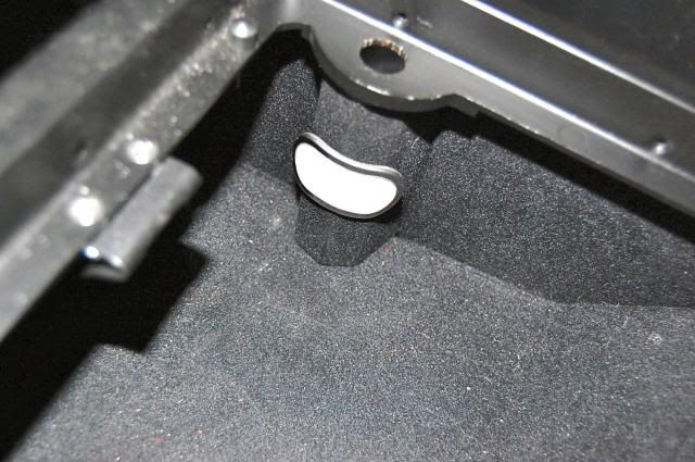
If look closely at your pic as well as mine, you will see a clip that is holding the lock cylinder in place, it looks similar to this:
Removing this clip will allow it to be removed; it won't be easy, but grabbing the tab with a pair of pliers and pulling should work. It will be harder to get that clip back into place when the cylinder is reinstalled; having a helper hold the cylinder in place while you try to slip the clip back in place would make it a little easier.
It might be a good idea to run a thin sharp knife blade around the cylinder escutcheon so no paint comes off with it when it is removed - especially if it looks like the car was painted without removing the cylinder.
Your current key switch might be ok; you need to check it for continuity between the 2 terminals while operating the switch before buying a new one. The back of the switch is in a really bad spot to access for troubleshooting....you would be better off to remove it to check it off the car, as well as to re-attach the wires to it.
If look closely at your pic as well as mine, you will see a clip that is holding the lock cylinder in place, it looks similar to this:
Removing this clip will allow it to be removed; it won't be easy, but grabbing the tab with a pair of pliers and pulling should work. It will be harder to get that clip back into place when the cylinder is reinstalled; having a helper hold the cylinder in place while you try to slip the clip back in place would make it a little easier.
It might be a good idea to run a thin sharp knife blade around the cylinder escutcheon so no paint comes off with it when it is removed - especially if it looks like the car was painted without removing the cylinder.
Good idea about the blade as the car was painted in 86. I'll have to buy a set of long pointy nose pliers then I'll tackle the clip.
Once removed, where do the wires that I need to reattach onto the lock connect to and how long will they have to be? I know its on the wiring diagram but just for clarification?
You need to crimp ring terminals on the wire ends to attach them to the switch; they are held on by small screws. I don't think it really matters which wire goes on which terminal, but this is how mine are connected:
The switch looks like this, you can see the threaded holes for the screws:
An example of a ring terminal:
As for the wire length, if you are going to do this with the cylinder removed, the wires will need to be long enough to go out through the same hole the cylinder is installed in so you can attach them to it; if they are not long enough, you will have to extend them enough to do this.
Otherwise, you will have to try and do all this with the cylinder in place.......and with the spare tire tub and gas tank in place, this will prove to be very difficult!!!
I'll definitely be removing the lock. Theres no way I'd tackle this job by leaving the lock in place, in fact I dont think its even possible with the spare tyre tub and tank in place. Its possible the lock may need to be replaced anyway. I just need to be very careful removing the lock, I'd be devastated if the paint chipped or was damaged.
I'll put in the same colour wires also, what gauge do the need to be? I'll also crimp some terminals on there. How long will the wires need to be?
According to the schematic, the orange wire is 20 gauge, and the pink wire is 14 gauge:
The wires will have to be as long as you need them to be to make the repairs; since yours have been cut, you may need to add length to them.
Hi Corvetteoz,
You are in good hands with 7t2vette's excellent step by step directions.
Hopefully, your switch is good because it may not be available anymore.
Others have brought a bad switch back to life by soaking it in two parts ammonia and one part hydrogen peroxide.
Just saying, in case you need it.
I would also put a piece of tape across the lock so that when you get the clip off, the lock doesn't have a chance to fall, jump, or otherwise scratch the car if it tries to fall. Just my paranoia showing thru....
Hi Corvetteoz,
You are in good hands with 7t2vette's excellent step by step directions.
Hopefully, your switch is good because it may not be available anymore.
Others have brought a bad switch back to life by soaking it in two parts ammonia and one part hydrogen peroxide.
Just saying, in case you need it.
Originally Posted by kansas123
I would also put a piece of tape across the lock so that when you get the clip off, the lock doesn't have a chance to fall, jump, or otherwise scratch the car if it tries to fall. Just my paranoia showing thru....
Got the car back yesterday after it had to have an exhaust manifold gasket replaced. What a difference. The car is nice and quiet and smooth now and it feels like it has a little more power as well.
Long weekend this weekend here so I should have time to tackle the lock. Good advice, thanks guys.
Last edited by Corvetteoz; 03-10-2016 at 09:25 AM.
Reason: Add
... Could someone chime in exactly how I can test these with my multi-meter? I know how to test for continuity but exactly how to do it I'm not sure? Do I need the alarm turned on and exactly what wires do I need to test? Also which of the door actuators activate the alarm, the ones to the rear of the car or the ones at the front of the doors? Thanks all.
Hi Corvetteoz,
Two questions :- Have you sorted your Alarm?? ... and ... Are you a Cockroach or CaneToad??

 03-05-2016, 08:36 AM


 . But seriously I have never tested for continuity before so this is why I ask.