When you click on links to various merchants on this site and make a purchase, this can result in this site earning a commission. Affiliate programs and affiliations include, but are not limited to, the eBay Partner Network.
Im in the process of finishing a 68 L71 that was started by a previous owner 20+ years ago. Paint done, mechanicals done, interior close, etc.
The problem is in getting the TI system working properly. Here is what I have done so far:
The car runs with a standard points distributor installed, but not with the TI distributor. I have used the information from Dave F. and the GM Service manual to diagnose the system. I have a ti box that was rebuilt by TI Spec. I have done the Breakerless ignition system trouble flow chart.
1. On the Circuit resistance test, I have 3.86 volts on the positive terminal of the coil with ignition key in on position.
2. I have done the distrib bench test and it reads 620 ohms
3. I have a new GM restoration 203 TI coil (DF says they are junk, other ti gurus say they are perfectly fine). It tests across the posts at .44 ohms
4. Amp box is grounded well
5. Original white coil wire is cut and spliced to the pink harness
6. Ive searched and read every thread on CF with the term "transistorized ignition" in it
Looking for further advice. Again, car starts and runs fine with non ti distributor, but will crank over fine but absolutely no spark with ti stuff hooked up.
Advice??
thanks, bigredbrad
Last edited by bigredbrad; 10-07-2016 at 03:50 PM.
I would verify continuity of the Pink and Grey wires that go from the Distributor plug to the Pulse Amp. Your Voltage sounds correct with Ignition on, does it go up when cranking (there is a wire from the Starter to boost spark during cranking. I recently did the same change on my L71 (p/o had a Unilite installed). but left me all the parts (- Coil) to change it back. I bought my Coil from Corvette Central and it works fine (6500 no problem)
I would be happy to buy a new amp, if I knew that was the problem. This is the one that I have now. Talked to Dave at TI Spec, and he confirmed that it is his work. This one has never been installed since the rebuild.
I guess I can buy a replacement upgraded board, just hate to spend the money when this one looks this good.
bigredbrad
Last edited by bigredbrad; 10-07-2016 at 05:10 PM.
Im in the process of finishing a 68 L71 that was started by a previous owner 20+ years ago. Paint done, mechanicals done, interior close, etc.
The problem is in getting the TI system working properly. Here is what I have done so far:
The car runs with a standard points distributor installed, but not with the TI distributor. I have used the information from Dave F. and the GM Service manual to diagnose the system. I have a ti box that was rebuilt by TI Spec. I have done the Breakerless ignition system trouble flow chart.
1. On the Circuit resistance test, I have 3.86 volts on the positive terminal of the coil with ignition key in on position.
2. I have done the distrib bench test and it reads 620 ohms
3. I have a new GM restoration 203 TI coil (DF says they are junk, other ti gurus say they are perfectly fine). It tests across the posts at .44 ohms
4. Amp box is grounded well
5. Original white coil wire is cut and spliced to the pink harness
6. Ive searched and read every thread on CF with the term "transistorized ignition" in it
Looking for further advice. Again, car starts and runs fine with non ti distributor, but will crank over fine but absolutely no spark with ti stuff hooked up.
Advice??
thanks, bigredbrad
I just noticed in your final photo the Pink pigtail connector appears to be connected to a different wire than my 68, on mine the pigtail wire goes to the starter R terminal wire extension.
I just noticed in your final photo the Pink pigtail connector appears to be connected to a different wire than my 68, on mine the pigtail wire goes to the starter R terminal wire extension.
SS - The yellowish wire connected to the pink extension is 1 of the 2 original engine harness wires. Originally, there were this wire and the white/red wire that connected to the - side of the coil. According to the wiring diagram on TI Spec, those 2 wires get clipped. The white/red gets capped and taped out of the way unused. The yellowish (off white) one gets a female spade terminal crimped onto it and plugged into the pink connector.
Did I read the wiring schematic wrong?
Last edited by bigredbrad; 10-07-2016 at 05:29 PM.
SS - The yellowish wire connected to the pink extension is 1 of the 2 original engine harness wires. Originally, there were this wire and the white/red wire that connected to the - side of the coil. According to the wiring diagram on TI Spec, those 2 wires get clipped. The white/red gets capped and taped out of the way unused. The yellowish (off white) one gets a female spade terminal crimped onto it and plugged into the pink connector.
Did I read the wiring schematic wrong?
I'm not sure at this point, my yellow is plastic coated that's why I noticed the dif. I would use an ohm meter to continuity check where each wire lands and verify against the schematic. It's easy to tell an 18g from 12g (the harness attached to the Dist. is 18g and the pink single pig is as well). That off white looks to be 12g in the pic.
The other thing you could do for the question I'm posing is to unplug the pig tail and measure voltage of the off white wire, it should be ~12VDC only when cranking and 0 the rest of the time.
I'm not sure at this point, my yellow is plastic coated that's why I noticed the dif. I would use an ohm meter to continuity check where each wire lands and verify against the schematic. It's easy to tell an 18g from 12g (the harness attached to the Dist. is 18g and the pink single pig is as well). That off white looks to be 12g in the pic.
The yellow is a 12g wire. Much larger than the pink. The photo is somewhat deceiving
Now I am questioning myself on the wire that goes inside to the ingition switch that picks up power.
I think you're onto it now, on mine the p/o moved connectors to work with a standard coil, I think it's because a standard Coil and Points switch the ground side of the Coil and the TI Sys. is switching the source Voltage to make spark.
For testing purposes, you can use an HEI module to replace the TI amp. I have done this and it works.
This will verify the TI dist, coil, and 12V supply is good.
The only thing left then to verify would be the TI amp and wiring.
Note: Ignore my color designation of the wires to the module, as I had the module mounted in a box and that was the harness I was using.
Thanks for the help guys. I really wanted to keep the car with its original K66 setup as it matches the tank sticker, and although a pain, I wanted to keep it original. So I went back to the drawing board, and removed the distributor, amp and wiring harness, planning to set up the entire system for a bench test.
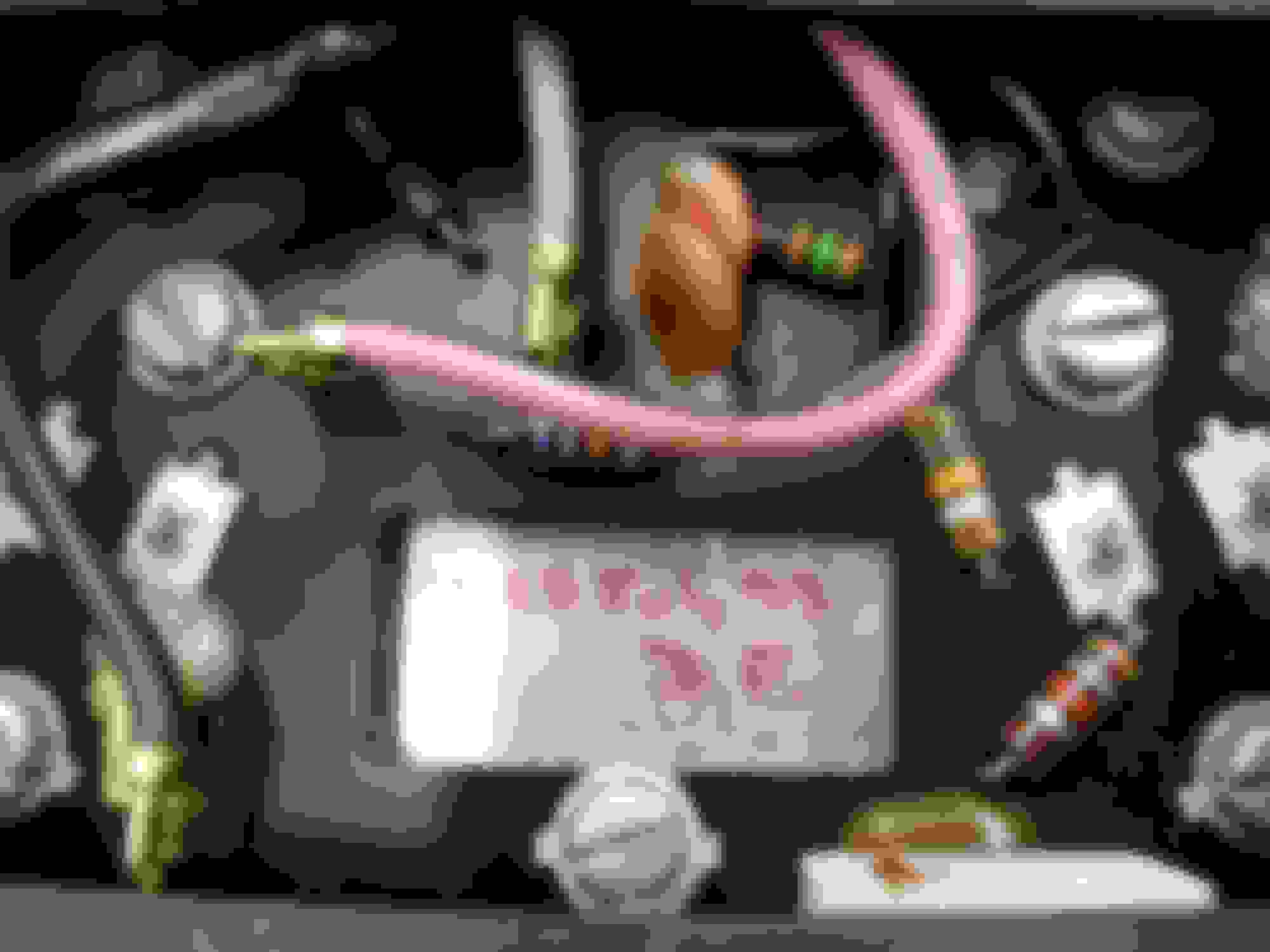
The first thing I did was use a wiring schematic and a VOM to check each wire for continuity to make sure that all wires were correct. To my wonder, I found that the pink and black wires were not correct from the harness plug to the coil. I ended up cutting the pink and black wires, resoldering them back together, the continuity then worked as shown in the wiring schematic. I reinstalled everything and the car started on the first crank!!
Here is a photo of my wiring correcting the problem so the car now runs. My question is: WTF?? How were the pink and black wire installed into the harness plug incorrectly? The rubber plug that attaches to the amp harness is untouched and hasnt been messed with. I completely stripped the harness and there are no other splices or alterations. Im stumped, although Im thrilled that the car now starts!
Thoughts? Suggestions?
Thanks for all the help.
bigredbrad
Last edited by bigredbrad; 10-11-2016 at 05:43 PM.
Thanks for the help guys. I really wanted to keep the car with its original K66 setup as it matches the tank sticker, and although a pain, I wanted to keep it original. So I went back to the drawing board, and removed the distributor, amp and wiring harness, planning to set up the entire system for a bench test.
The first thing I did was use a wiring schematic and a VOM to check each wire for continuity to make sure that all wires were correct. To my wonder, I found that the pink and black wires were not correct from the harness plug to the coil. I ended up cutting the pink and black wires, resoldering them back together, the continuity then worked as shown in the wiring schematic. I reinstalled everything and the car started on the first crank!!
Here is a photo of my wiring correcting the problem so the car now runs. My question is: WTF?? How were the pink and black wire installed into the harness plug incorrectly? The rubber plug that attaches to the amp harness is untouched and hasnt been messed with. I completely stripped the harness and there are no other splices or alterations. Im stumped, although Im thrilled that the car now starts!
Thoughts? Suggestions?
Thanks for all the help.
bigredbrad
Glad you found your problem......next time you can go inside the amplifier unit and swap the spade connectors on the circuit board instead of cutting up the external wiring harness. K-66 troubles can be frustrating to diagnose and solve....1960's electronics in their finest hour!
Ok, so this is what I have to look forward too. My L89 is a complete basket case. Wires from what, I don't know. All kinds of rigs. I do have another proper 68 motor and forward. Just picked up a to harness.
Basically, the amp was there, but not hooked up. It had an HEI with the ballast clipped and by passed. I sent the amp out years ago to get it redone.
As soon as the weather breaks, I'll be next in line with question.
One thing I did was take a lot of pics from various shows of the wiring and misc... Problem is my ex wife, swiped everything including the camera, pics, computer, flash drives... Basically, the house wasn't enough... Ugh
Last actual post here was about 5 years ago. Start a new thread with your question, whenever that is.

 10-07-2016, 02:25 PM