I need a wiring diagram / schematic for 1988 computer
 05-06-2006, 02:48 PM
#1
Instructor

Thread Starter
Member Since: Mar 2005
Location: Shreveport Louisiana
Posts: 130
Likes: 0
Received 0 Likes
on
0 Posts
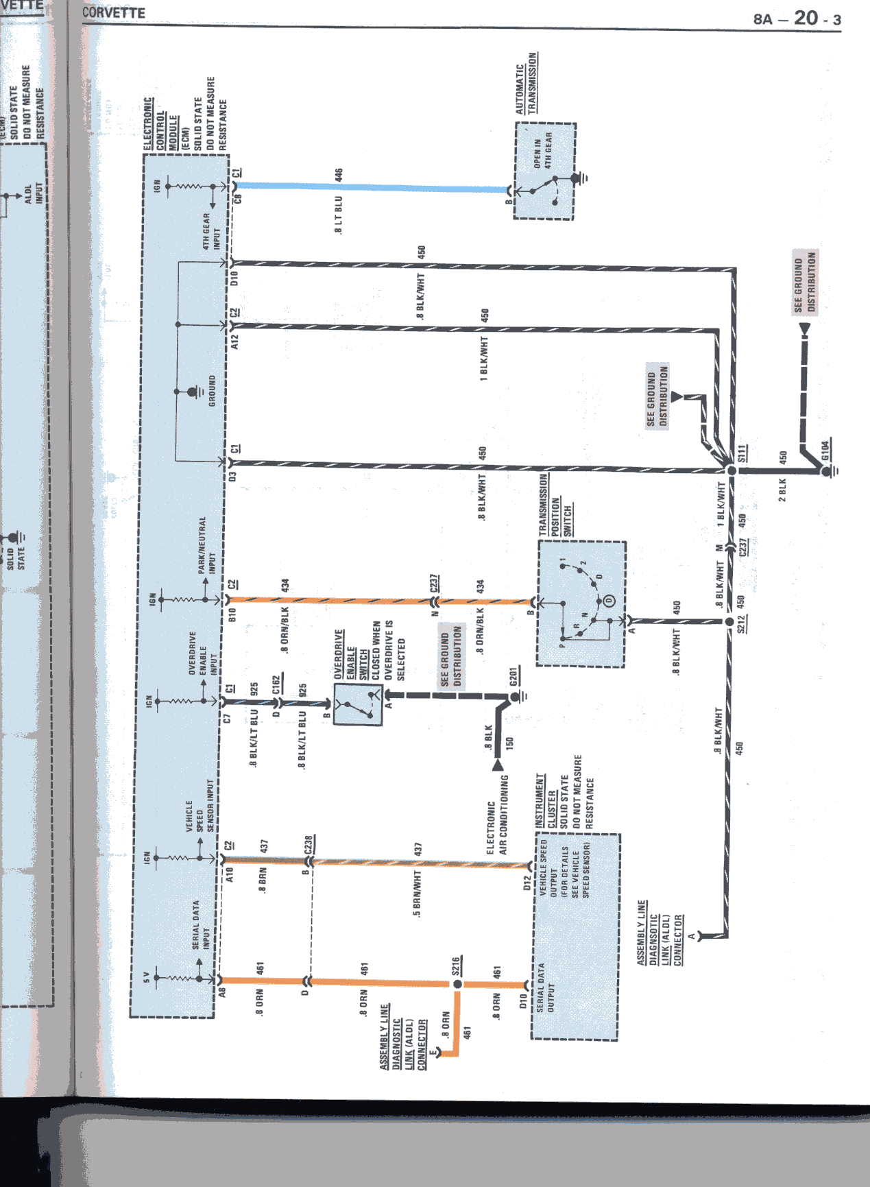
I need the wiring diagram / schematic for the computer for the 1988 TPI (specifically the power, ground and vehicle speed sensor that runs to the ECM, colors and location on the 2 plug-ins).
 05-06-2006, 04:38 PM
#2

I scanned a couple pages out of my electrical manual (88) that may be helpful. They are pretty big so I won't insert them here. You can see them at the following links:
http://myc4.freeservers.com/images/file0043.jpg
and
http://myc4.freeservers.com/images/file0044.jpg
Good Luck,
Ron
http://myc4.freeservers.com/images/file0043.jpg
and
http://myc4.freeservers.com/images/file0044.jpg
Good Luck,
Ron
 on both of them. Thanks for trying.
05-06-2006, 08:23 PM
on both of them. Thanks for trying.
05-06-2006, 08:23 PM
#4
Burning Brakes

Member Since: Jun 2004
Location: richardson tx
Posts: 752
Likes: 0
Received 0 Likes
on
0 Posts
Originally Posted by Supernatural
I need the wiring diagram / schematic for the computer for the 1988 TPI (specifically the power, ground and vehicle speed sensor that runs to the ECM, colors and location on the 2 plug-ins).
05-06-2006, 11:32 PM
#5
Instructor
Thread Starter
Member Since: Mar 2005
Location: Shreveport Louisiana
Posts: 130
Likes: 0
Received 0 Likes
on
0 Posts
Yes, if you could please send me the schematic / diagrams to my mail box that would be great. I am trying to install a speedo calibrator box in between the speed sensor wire. I swapped 3.07's for 3.45's. The 1988 has a 4+3 in it, if that makes a difference in wire color.
05-07-2006, 12:35 AM
#7
Burning Brakes
Member Since: Jun 2004
Location: richardson tx
Posts: 752
Likes: 0
Received 0 Likes
on
0 Posts
i dont think i can attach anything here on the forum. you know after all these years i still dont know how to add a pic to my post other than a link to a freebee host? seems its an act of god. not a hoop i want to jump thru. but i understand the admin position on space. if everybody could just copy and past then we would all be paying a monthly fee. i can scan to pdf and email you want you want. pm me with your address.
05-07-2006, 12:46 AM
#8
Instructor
Thread Starter
Member Since: Mar 2005
Location: Shreveport Louisiana
Posts: 130
Likes: 0
Received 0 Likes
on
0 Posts
Is it really that easy, just 30 minutes and a $5.00 part? I thought you had to remove the drive shaft and take apart the tail housing to get to the speedo gear in the trans. Has anyone done this in a 4+3 that can give some detail instruction on this.
05-07-2006, 01:09 AM
#9
Team Owner

Member Since: May 2002
Location: San Diego , CA Double Yellow DirtBags 1985..Z51..6-speed
Posts: 24,337
Likes: 0
Received 17 Likes
on
16 Posts
Originally Posted by Supernatural
Is it really that easy, just 30 minutes and a $5.00 part? I thought you had to remove the drive shaft and take apart the tail housing to get to the speedo gear in the trans. Has anyone done this in a 4+3 that can give some detail instruction on this.
Well, the closest you can get without changing the tailshaft gear is a 17/45 ratio, optimal for a 26.3" tire, so you'll have about 3-4% speedo error, depending on exactly how tall your tire is (should be 25-25.5 inches)
If you go this route, get GM p/n 25513052. Simply unplug the speedo sensor, remove the hold down bolt, catch the 1/2 cup of ATF that comes out, and slip the new gear on and slap it back together.
A more accurate speedo would require opening the trans, or using the adapter.
05-07-2006, 02:02 AM
#10
Instructor
Thread Starter
Member Since: Mar 2005
Location: Shreveport Louisiana
Posts: 130
Likes: 0
Received 0 Likes
on
0 Posts
Thanks, I will have to give that a try. It does not sound that bad. There are 2 tests that I tried, to see how far off I was. I was driving next to someone. They were doing 45mph and I showed 52mph. That was 1.18 to 1. Then I drove a distance of 1 mile in my other car and then drive the Vette the same exact distance. The trip meter showed 1.2 miles distance, so that is 1.2 to 1. So both tests are very close math wise. I am currently running on 255 50 16's on the stock 1988 16" wheels. I will be upgrading in the future to 2006 ZO6 style 18X9.5 in front and 18X10.5 in the rear.
05-07-2006, 04:26 PM
#12
Melting Slicks

If you do go with an electronic ratio adapter like the dakota digital SGI-5. You must correct the VSS signal to the instrument cluster. The cluster gets the signal first and then outputs to the ecm.
If you correct the ecm input only, the speedo will still be off.
Personally I think this is the easier approach than swapping the drive and driven gears and possibly the vss. Gears may work out to be a little cheaper depending upon your needs. Others will surely disagree.
The advantage of electronic adaptors is that they can be dialed nearly exactly for any tire gear combination, and can be easily changed to support future tire/gear changes.