Aftermarket Keyless Entry Help
 03-23-2010, 04:54 PM
#1
Burning Brakes

Thread Starter


I purchased a IC Dynamics model 2RTA remote keyless entry system from JC Whitney.
I decided to install this in the drivers door due to the location of all of the wires needed and a safe place to install.
I ordered a FSM on 3/12, but it has not arrived yet. After looking up info on here, i decided to give this a shot.
This is for a 1991 coupe.
There are 10 wires to hook up for the harness they give you. They are as followed:
Harness:
White w/ fuse (polarity input) (on the 5 wire reverse polairty diagram it says to hook up to +12 volts)
Car:
Orange @ lock switch
Harness:
Red w/ fuse (constant 12v+)
Car:
Orange @ lock switch
Harness:
Brown (trunk relase polarity)
Car:
None yet, figuring out locks first
Harness:
Black (chassis Ground -)
(How do i get a chassis ground on a fiberglass door? Id like to go to the frame somewhere but I want to keep this install in the door)
Car:
Black wire at power window switch
Harness:
Orange (trunk relase button)
Car:
None yet, figuring out locks first
Harness:
Gray (Unlock switch side 5RP only)
Car:
Black w/ white stripe @ lock switch
Harness:
Green (Door Unlock)
Car:
Unsure. I tried both the tan and gray wires but this caused a short and blew the fuse when I went and pushed the lock or unlock switch. Nothing has worked with the Key Fobs yet.
Harness:
Blue (Lock switch side)
Car:
Light Blue @ lock switch
Harness:
Purple ( Ignition +12 v)
i can do without this option. It locks/unlocks doors @ key on/off
Car:
Pink @ power window switch
Harness:
Yellow (door lock)
Car:
Unsure. I tried both the tan and gray wires but this caused a short and blew the fuse when I went and pushed the lock or unlock switch. Nothing has worked with the Key Fobs yet.
I think I have the blue and gray wires right, along with the white and red.
Where do i put the Green and yellow wires? Am i grounding to the correct place? I really need that manual to come in.
Any help would be greatly appreciated.
Here is a link to the instruction from IC Dynamics/ JC whitney
http://www.jcwhitney.com/remote-cont...DetailTabPanel
Click there then look for install instructions on the left side of the page
Thank you,
Mike
Last edited by Deepa; 03-23-2010 at 05:54 PM.
 03-23-2010, 08:51 PM
#2
Melting Slicks


Member Since: Aug 1999
Location: Baltimore, MD USA
Posts: 2,240
Likes: 0
Received 34 Likes
on
30 Posts

This is the door lock schematic for a 86-90. Not sure the 91 is the same, so use this information at your own risk.
I think it's easier to do the installation on the driver side in the
driver side foot well area.
Do not install the module inside the door because water can shed off the window into the inside of the door which will damage the control module.
****Disconnect the negative battery terminal before you make any wiring connections.****
This is a link to Agent86's door lock schematic.
http://members.shaw.ca/agent86/Power%20Door%20Locks.pdf
There is a Light Blue wire and a Black wire coming from the driver side door lock switch that enters the interior of the car via the driver side kick panel area.
The Light Blue wire is the Unlock control wire.
The Black wire is the Lock control wire.
Make sure by tracing the wires back to the driver side door lock switch that you have the proper wires before you cut them.
Both of these wires you cut in half.
Light Blue wire end going back to the driver side door lock switch
connect to Control Module: Green wire.
Light Blue wire end going over to the passenger side door lock switch connect to Control Module: Gray wire.
Black wire end going back to driver side door lock switch connect
to Control Module: Yellow wire.
Black wire end going back to passenger side door lock switch
connect to Control Module: Blue wire.
Control Module: Red wire is power for the Module and should be fused.
Connect this wire to a Hot at all times 12 volt source.
The Orange wire at the Ignition Switch which is mounted on the top middle of the steering column can be used to tap off to get a Hot at all times 12 volts. *** not an Orange wire at the door lock switch as you posted.***
If you want to use the Hot at all times 12 volts at the Driver side door lock switch the wire is Orange/Black.
The Pink wire at the Ignition Switch is a source for a Switched 12 volts.
Control Module: Connect White wire to the Control Module Red wire so it also has 12 volts at all times.
Control Module: Black wire is ground for the Control Module so you need to connect it to a grounded source.
Control Module: Purple wire should be connect to a Switched 12 volt source.
This will allow the Control module to Lock the doors when the ignition is turned on and Unlock the doors when the ignition is turned off.
Last edited by Hooked on Vettes; 03-24-2010 at 01:09 AM.
03-24-2010, 09:09 AM
#3
Burning Brakes
Thread Starter
thanks for the reply and the wiring. Ill pull apart the drivers side foot well and give it a go over there with your instructions.
Whats a good wire to tie into for ground?
As for the hatch, which wire goes where? Or just tie in and see which way works?
Thanks
Mike
Whats a good wire to tie into for ground?
As for the hatch, which wire goes where? Or just tie in and see which way works?
Thanks
Mike
Last edited by Deepa; 03-24-2010 at 09:12 AM.
03-24-2010, 10:03 AM
#4
Melting Slicks
The wiring sounds close to my 92, IIRC. I put my keyless in 4 years ago.
On the 92, there was an extra board with 2 relays required to run the locks, your system may or maynot need this.
Ditto on not putting the module in the door. I put mine in the pass side, above the carpeted panel, just under he glovebox.
The orange hatch wire is easily found under the console trim panel, pull the hinged cover and the panel. The orange wire grounds the hatch relay when the manual button is pushed.
It's also a good opportunity to put in an antenna switch to keep the antenna down when you play tapes (or CDs).
There's a decent ground (92) above the drivers side carpeted kickpanel, left side of the foot well.
03-24-2010, 01:17 PM
#5
Melting Slicks
Member Since: Aug 1999
Location: Baltimore, MD USA
Posts: 2,240
Likes: 0
Received 34 Likes
on
30 Posts
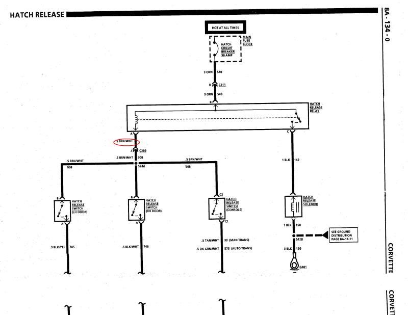
Here's the schematic for a 90 Vette. Don't know if the color code of the wires are the same for a 91. There are different ways to get the remote hatch release to work.
You can tap into the wire at the center console hatch release button or tap into the wire at the driver side door hatch release button located on the back edge of the door panel.
Either method you choose, at the switch will be two wires. One wire is hot at all times and will have around 12 volts on it.
In the schematic the wire is shown as Brown/White.
You splice/tap the Orange wire from the Control Module to that
wire.
You connect the Brown wire from the Control Module to a ground.
This will allow the remote hatch release to work even though the doors are closed and the transmission is not in Park or Neutral for an auto transmission or with out the parking brake on for a manual transmission.
 03-26-2010, 12:29 PM
#6
Burning Brakes
Thread Starter
OK so i got it all installed and working. Thank you for all of your help.
I hooked up the purple wire which locks/unlocks the doors at ignition on/off. Well the 91 was the first year to have that 15 minute accessory power delay, so it does not unlock until I open a door, which I cant do because the door is still locked. I have to go in and snip that purple wire and all will be well.
Thanks again for all of your help.
Mike
04-07-2010, 02:04 PM
#7
Race Director


OK so i got it all installed and working. Thank you for all of your help.
I hooked up the purple wire which locks/unlocks the doors at ignition on/off. Well the 91 was the first year to have that 15 minute accessory power delay, so it does not unlock until I open a door, which I cant do because the door is still locked. I have to go in and snip that purple wire and all will be well.
Thanks again for all of your help.
Mike
I hooked up the purple wire which locks/unlocks the doors at ignition on/off. Well the 91 was the first year to have that 15 minute accessory power delay, so it does not unlock until I open a door, which I cant do because the door is still locked. I have to go in and snip that purple wire and all will be well.
Thanks again for all of your help.
Mike
04-08-2010, 09:18 AM
#8
Burning Brakes
Thread Starter
yeah, i really like it. Its easy to use for sure.
You would be ok connecting the purple wire, because you dont have power for 15 mins after the key is turned off. On my 91, there is power until you open the door, but you cant because its still locked from when you put the key in.
I ended up installing it in the door but shrinkwrapped the whole thing and velcroed it out of the way.
I had an issue where the wire harness conector for the keyless module didnt make contact when fully seated. I messed with mine a bit and then it was fine.
Mike
04-08-2010, 10:24 AM
#9
Melting Slicks
OK so i got it all installed and working. Thank you for all of your help.
I hooked up the purple wire which locks/unlocks the doors at ignition on/off. Well the 91 was the first year to have that 15 minute accessory power delay, so it does not unlock until I open a door, which I cant do because the door is still locked. I have to go in and snip that purple wire and all will be well.
Thanks again for all of your help.
Mike
I hooked up the purple wire which locks/unlocks the doors at ignition on/off. Well the 91 was the first year to have that 15 minute accessory power delay, so it does not unlock until I open a door, which I cant do because the door is still locked. I have to go in and snip that purple wire and all will be well.
Thanks again for all of your help.
Mike
IIRC, I had it on in my 92 when I first fired the system up, don't recall a problem with the delay. But I did turn it off when I first programed all the features.