What grade Aluminum are the upper control arms?
 06-11-2010, 01:23 PM
#1
Le Mans Master

Thread Starter
Member Since: Oct 2007
Location: Akron Ohio
Posts: 8,868
Received 1,749 Likes
on
941 Posts
2023 C5 of the Year Finalist - Modified
2022 C5 of the Year Finalist - Modified
St. Jude Donor '09-'10-'11

I am looking into making my own adjustable upper control arms and was wondering if 6061 T6 Aluminum is strong enough? Im made the cross shaft out of the T6 and then Im going to put heim joints on the end and use adjustable sleeves. Do you guys think T6 is strong enough for this?
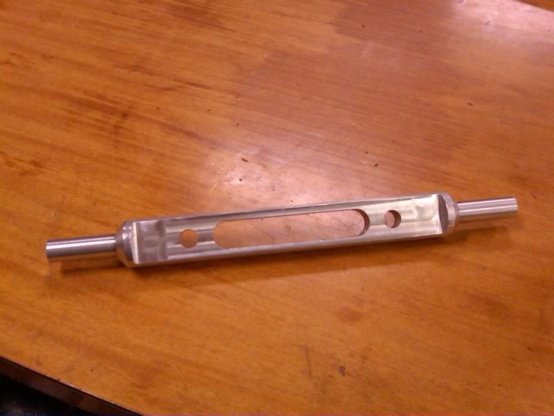
Just looking for some other opinions. I did some FEA on it but wasnt sure what load to use for it.
Just looking for some other opinions. I did some FEA on it but wasnt sure what load to use for it.
 06-11-2010, 01:43 PM
#2
Safety Car

Brian Cunningham might have some idea. I know he has been making CAD drawings of the entire C4 suspension, maybe he has an idea of the loads exerted on the arm.
06-11-2010, 02:54 PM
#3
Drifting

Member Since: Oct 2003
Location: CALGARY ab
Posts: 1,594
Likes: 0
Received 0 Likes
on
0 Posts

when using any aluminium in a stress application as in "A" arms.. the best material is 70 (70,000psi tensil strength) series aluminium.. less prong to stress cracking then 6061 t-1 series.. if in doubt refer to "american engineering & Welding specification" handbook for proper application guides..
another concern would be if the construction doesnt conform to "orginal manufacture equipment" your efforts are in vien... insurance will not cover modified equipment with out GOVERNMENT Quality Control and inspection!! think twice about this!!
another concern would be if the construction doesnt conform to "orginal manufacture equipment" your efforts are in vien... insurance will not cover modified equipment with out GOVERNMENT Quality Control and inspection!! think twice about this!!
Last edited by korvette4u; 06-11-2010 at 02:59 PM.
06-11-2010, 02:57 PM
#4
Burning Brakes


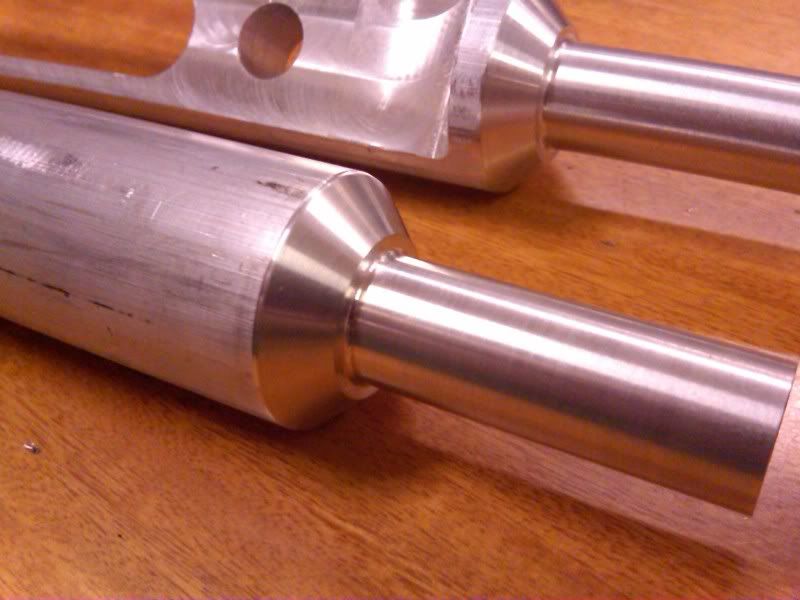
Well, your comparing a billet piece versus a cast piece. If you create an identical piece, the billet will undoubtedly be stronger. Here, your altering the design entirely, so it's going to be up to you to calculate the loads involved and establish if the piece will work reliably. If you could get some data and then do some software strain analysis that'd be the way. Your placing that piece in shear and dividing it by two arms, so getting some numbers of the shear strength of that material then a guess of the loads involved would help.
That or you can do it the old school way and simply bolt it up and do some trial testing, increasing loads and doing some inspections.
That or you can do it the old school way and simply bolt it up and do some trial testing, increasing loads and doing some inspections.
Last edited by Z06X; 06-11-2010 at 02:59 PM.
06-11-2010, 03:00 PM
#5
Team Owner

Member Since: Mar 2001
Location: Boston, Dallas, Detroit, SoCal, back to Boston MA
Posts: 30,606
Received 239 Likes
on
167 Posts

I'm thinking T6 would be fine
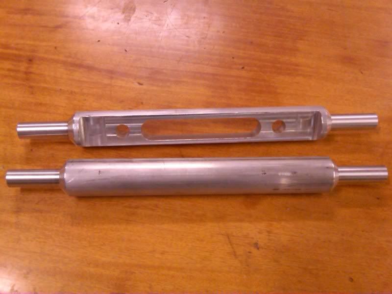
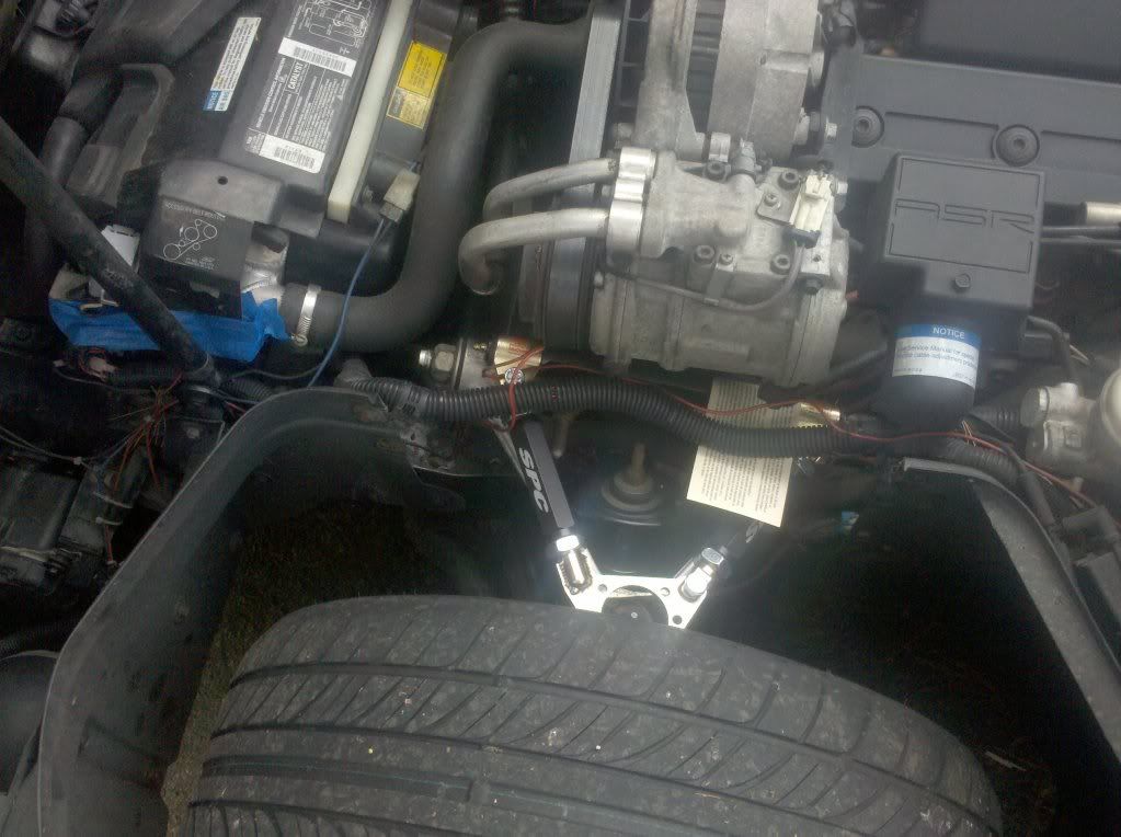
are those the stock dimensions?
here's my adjustables
compare to the stockers they're a lot smaller, but they're also a lot stiffer.
are those the stock dimensions?
here's my adjustables
compare to the stockers they're a lot smaller, but they're also a lot stiffer.

 I love it when you talk dirty
 06-12-2010, 12:04 AM
#9
Le Mans Master
Thread Starter
Member Since: Oct 2007
Location: Akron Ohio
Posts: 8,868
Received 1,749 Likes
on
941 Posts
2023 C5 of the Year Finalist - Modified
2022 C5 of the Year Finalist - Modified
St. Jude Donor '09-'10-'11
Well, your comparing a billet piece versus a cast piece. If you create an identical piece, the billet will undoubtedly be stronger. Here, your altering the design entirely, so it's going to be up to you to calculate the loads involved and establish if the piece will work reliably. If you could get some data and then do some software strain analysis that'd be the way. Your placing that piece in shear and dividing it by two arms, so getting some numbers of the shear strength of that material then a guess of the loads involved would help.
That or you can do it the old school way and simply bolt it up and do some trial testing, increasing loads and doing some inspections.
That or you can do it the old school way and simply bolt it up and do some trial testing, increasing loads and doing some inspections.
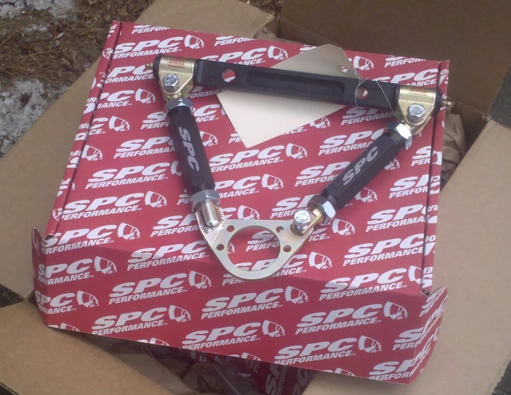
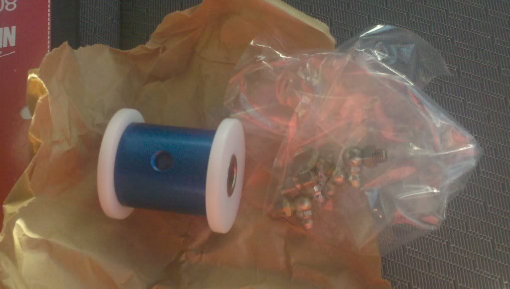
The dimensions are very close to stock. I dont have the money for those SPC ones, but they are the ones I am replicating. I am using heim joints instead of the bushings, but the setup is similar. I got the T6 material from my school and made the cross piece in my CNC class, Tom at Banski hooked me up with some heim joints, and I am making the ball joint plates at work. All in all I think I have less than $100 in for both arms.

Thanks for all the input guys. It sounds like this should be ok from the comments. I agree that something like 7075 would have been better but this was the best aluminum my CNC class professor wanted to buy!
 06-12-2010, 08:46 AM
#10
Melting Slicks

Member Since: Sep 2008
Location: Cherokee National Forest TN
Posts: 2,376
Likes: 0
Received 102 Likes
on
92 Posts
Lateral loading during cornering is normally not the major concern with upper A arms as the A arm is either in compression or tension. IE: at work 90* from the vehicle longitudinal center line.
IMHO the issue of major concern is increased loading during HEAVY BRAKE application on corner entry with the major forces being applied to the suspension components that are positioned at the outside radius of the corner. The forward leg on the upper arm is in compression, the rear leg of the arm is in tension while the spindle acting as a lever (moment arm) pivoting on the lower ball joint is atempting to twist the entire upper arm assembly off the frame.
I have seen the adjustable leg A arms fail on oval track cars.
Good luck with your projects.
06-12-2010, 10:49 AM
#11
Race Director

 06-12-2010, 10:54 AM
#12
Racer

7000 series is better then the 6000, it's stiffer and stronger. That's why when mountain bike frame makers started building frames with 7000 series a few years ago it was a step forward in the technology as a more rigid bike frame is better. As far as I know 6000 series is still readily available, and is popular for machining and easy to work with and will bend more before snapping.
Last edited by black88z51; 06-12-2010 at 11:01 AM.
06-12-2010, 12:34 PM
#13
Le Mans Master
Thread Starter
Member Since: Oct 2007
Location: Akron Ohio
Posts: 8,868
Received 1,749 Likes
on
941 Posts
2023 C5 of the Year Finalist - Modified
2022 C5 of the Year Finalist - Modified
St. Jude Donor '09-'10-'11
Lateral loading during cornering is normally not the major concern with upper A arms as the A arm is either in compression or tension. IE: at work 90* from the vehicle longitudinal center line.
IMHO the issue of major concern is increased loading during HEAVY BRAKE application on corner entry with the major forces being applied to the suspension components that are positioned at the outside radius of the corner. The forward leg on the upper arm is in compression, the rear leg of the arm is in tension while the spindle acting as a lever (moment arm) pivoting on the lower ball joint is atempting to twist the entire upper arm assembly off the frame.
I have seen the adjustable leg A arms fail on oval track cars.
Good luck with your projects.
IMHO the issue of major concern is increased loading during HEAVY BRAKE application on corner entry with the major forces being applied to the suspension components that are positioned at the outside radius of the corner. The forward leg on the upper arm is in compression, the rear leg of the arm is in tension while the spindle acting as a lever (moment arm) pivoting on the lower ball joint is atempting to twist the entire upper arm assembly off the frame.
I have seen the adjustable leg A arms fail on oval track cars.
Good luck with your projects.
7000 series is better then the 6000, it's stiffer and stronger. That's why when mountain bike frame makers started building frames with 7000 series a few years ago it was a step forward in the technology as a more rigid bike frame is better. As far as I know 6000 series is still readily available, and is popular for machining and easy to work with and will bend more before snapping.
06-12-2010, 01:17 PM
#14
Racer
I am looking into making my own adjustable upper control arms and was wondering if 6061 T6 Aluminum is strong enough? Im made the cross shaft out of the T6 and then Im going to put heim joints on the end and use adjustable sleeves. Do you guys think T6 is strong enough for this?
.
.
06-13-2010, 11:32 AM
#15
Burning Brakes

So, what can your pull in a corner? 1 g? 1-1/4 g? < 1 g? Whatever that number is will give you a starting point. I think for most C4s with fuel and driver you're looking @ 3000 to 3500 lb.
Apply that force and run the analysis to see what kind of stesses are present and adjust from there.
Keep in mind though that in a case like this you're likely going to design to more criteria than just strength. Things like ease of assembly, mating up to standard components or hardware (like in your case the rod ends) come into play as well. You might end up finishing your design to these practical considerations and then running the analysis to make sure it will stand up.
FEA is a great tool but like any other it's only as good as the info that is put in. So, be mindful of the constraints used to make sure they're realistic.
There's no better test than real world application. You're in a good position because your car is street driven as well as tracked. Install your stuff and go for a little spin on a not so smooth local road. If it survives that, drive it for a while and see how it stands up. Then take it to the track and be observant the first few sessions out to see how it feels. After the event a tear down and inspection is a great way to get info about what's really going on. "Autopsies" on new designs can be very enlightening.
06-13-2010, 12:24 PM
#16
Le Mans Master
Member Since: Feb 2000
Location: Bedford NH
Posts: 5,708
Likes: 0
Received 1 Like
on
1 Post
Cruise-In II Veteran
Well, you must consider many things that nobody has mentioned here. First of all, the only real source for your material properties should be referenced from Mil-Hdbk-5 for metallics. Realistically, the biggest loads that a Corvette control arm will see are the impact loads due to hitting a curb or pot hole. That is pretty hard to characterize exactly, so you are going to have to make some assumptions. I think that having the entire car on one wheel, times 1.5x, is reasonable in my experience (for the wheel loads, not for each individual suspension link). We use that criterion with our Penske shock parts, like our lower "T" bar shock mounts, upper clevis mounts, etc, and they are neither excessively heavy, nor has anyone ever even one yielded them yet.
To limit this discussion to 6061 and 7075, 6061 is the better choice here. Since this is a clean sheet design, you can increase the sections to use it and 6061 does not suffer from stress corrosion cracking to anywhere the extent that 7075 has (depending on the heat treatment). Alloy 7075 can have serious susceptibility to stress corrosion cracking at most common heat treatments that will show up in areas that have built in prestress like the corners of a clevis that does not fit perfectly. In addition, 7075 is considered not weldable even though if you take a TIG to it, it will weld, look good, but the material properties in that area are terrible. Alloy 6061 is cheap, easy to machine, and easy to anodize.
If you want to do an FEA, what are you going to use for you pass-fail criterion? Your output will be in Von Mises stress, which is the tensile equivalent to the octahedral shear stress. That is nice, but are you just going to plug in the FEA the tensile yield value that you look up? If you want to make it last a long time and want to consider fatigue, I think the modified Goodman criterion is a more reasonable value. If you not not familiar with it, it is more appropriate for things that see some positive stress value and cycle +/- about that positive value, like an aircraft spar, or car suspension, that is supporting the entire weight of the aircraft then sees bumps about that positive value. Again, Mil-Hdbk-5 will provide you with the allowables for whatever stress criterion that you deem appropriate. Good luck, but if I may, at TRW and L-M we had zillions of resources, and we still had the attitude that 1 test is worth 100 opinions.
Last edited by ghoffman; 06-13-2010 at 01:05 PM.
06-13-2010, 12:39 PM
#17
Burning Brakes
Thanks for the clarification on the 7075 material properties and the 1.5 g starting point for design.
 because we all know what opinions are like? And that everybody has one
because we all know what opinions are like? And that everybody has one
06-13-2010, 03:49 PM
#18
Burning Brakes
The easy way to buy your self some pice of mind, Do some side by side destructive load testing. Your custom fab part next to the OEM. Maby fab some up for the local short oval guys too.
06-13-2010, 09:37 PM
#19
Team Owner
Member Since: Mar 2001
Location: Boston, Dallas, Detroit, SoCal, back to Boston MA
Posts: 30,606
Received 239 Likes
on
167 Posts
the lowers got these, greaseable del-alum bushings
they're available to the tops as well, if you want to keep the stockers
I wanted to added adjustment to autoxing.
 06-13-2010, 11:57 PM
#20
Le Mans Master
Thread Starter
Member Since: Oct 2007
Location: Akron Ohio
Posts: 8,868
Received 1,749 Likes
on
941 Posts
2023 C5 of the Year Finalist - Modified
2022 C5 of the Year Finalist - Modified
St. Jude Donor '09-'10-'11
Well, you must consider many things that nobody has mentioned here. First of all, the only real source for your material properties should be referenced from Mil-Hdbk-5 for metallics. Realistically, the biggest loads that a Corvette control arm will see are the impact loads due to hitting a curb or pot hole. That is pretty hard to characterize exactly, so you are going to have to make some assumptions. I think that having the entire car on one wheel, times 1.5x, is reasonable in my experience (for the wheel loads, not for each individual suspension link). We use that criterion with our Penske shock parts, like our lower "T" bar shock mounts, upper clevis mounts, etc, and they are neither excessively heavy, nor has anyone ever even one yielded them yet.
To limit this discussion to 6061 and 7075, 6061 is the better choice here. Since this is a clean sheet design, you can increase the sections to use it and 6061 does not suffer from stress corrosion cracking to anywhere the extent that 7075 has (depending on the heat treatment). Alloy 7075 can have serious susceptibility to stress corrosion cracking at most common heat treatments that will show up in areas that have built in prestress like the corners of a clevis that does not fit perfectly. In addition, 7075 is considered not weldable even though if you take a TIG to it, it will weld, look good, but the material properties in that area are terrible. Alloy 6061 is cheap, easy to machine, and easy to anodize.
If you want to do an FEA, what are you going to use for you pass-fail criterion? Your output will be in Von Mises stress, which is the tensile equivalent to the octahedral shear stress. That is nice, but are you just going to plug in the FEA the tensile yield value that you look up? If you want to make it last a long time and want to consider fatigue, I think the modified Goodman criterion is a more reasonable value. If you not not familiar with it, it is more appropriate for things that see some positive stress value and cycle +/- about that positive value, like an aircraft spar, or car suspension, that is supporting the entire weight of the aircraft then sees bumps about that positive value. Again, Mil-Hdbk-5 will provide you with the allowables for whatever stress criterion that you deem appropriate. Good luck, but if I may, at TRW and L-M we had zillions of resources, and we still had the attitude that 1 test is worth 100 opinions.
To limit this discussion to 6061 and 7075, 6061 is the better choice here. Since this is a clean sheet design, you can increase the sections to use it and 6061 does not suffer from stress corrosion cracking to anywhere the extent that 7075 has (depending on the heat treatment). Alloy 7075 can have serious susceptibility to stress corrosion cracking at most common heat treatments that will show up in areas that have built in prestress like the corners of a clevis that does not fit perfectly. In addition, 7075 is considered not weldable even though if you take a TIG to it, it will weld, look good, but the material properties in that area are terrible. Alloy 6061 is cheap, easy to machine, and easy to anodize.
If you want to do an FEA, what are you going to use for you pass-fail criterion? Your output will be in Von Mises stress, which is the tensile equivalent to the octahedral shear stress. That is nice, but are you just going to plug in the FEA the tensile yield value that you look up? If you want to make it last a long time and want to consider fatigue, I think the modified Goodman criterion is a more reasonable value. If you not not familiar with it, it is more appropriate for things that see some positive stress value and cycle +/- about that positive value, like an aircraft spar, or car suspension, that is supporting the entire weight of the aircraft then sees bumps about that positive value. Again, Mil-Hdbk-5 will provide you with the allowables for whatever stress criterion that you deem appropriate. Good luck, but if I may, at TRW and L-M we had zillions of resources, and we still had the attitude that 1 test is worth 100 opinions.
7075 is a better choice on paper because it does have higher strength but practically is it more expensive as you've found out and much care must be taken if any anodizing is done to the finished part. If the parts are not anodized correctly it can actually weaken the part.
A general rule of thumb for a starting point in your FEA can be assuming a worst case scenario: that the full cornering load of the car is put on that one component. Yes, this is likely overkill but should also tell you what ballpark you're playing in.
So, what can your pull in a corner? 1 g? 1-1/4 g? < 1 g? Whatever that number is will give you a starting point. I think for most C4s with fuel and driver you're looking @ 3000 to 3500 lb.
Apply that force and run the analysis to see what kind of stesses are present and adjust from there.
Keep in mind though that in a case like this you're likely going to design to more criteria than just strength. Things like ease of assembly, mating up to standard components or hardware (like in your case the rod ends) come into play as well. You might end up finishing your design to these practical considerations and then running the analysis to make sure it will stand up.
FEA is a great tool but like any other it's only as good as the info that is put in. So, be mindful of the constraints used to make sure they're realistic.
There's no better test than real world application. You're in a good position because your car is street driven as well as tracked. Install your stuff and go for a little spin on a not so smooth local road. If it survives that, drive it for a while and see how it stands up. Then take it to the track and be observant the first few sessions out to see how it feels. After the event a tear down and inspection is a great way to get info about what's really going on. "Autopsies" on new designs can be very enlightening.
In my FEA I used a load of the corner weight (~950lbs) times the 1.5g's it can pull in a corner (estimate worst case like you said). I dont recall the number off hand but the deflection was low and the stress was below the ultimate yield strength by a safety factor of over 2.