Coolant flow diagram
 01-06-2011, 11:26 PM
#1
Burning Brakes

Thread Starter

Member Since: Oct 2009
Location: Minneapolis MN
Posts: 773
Likes: 0
Received 0 Likes
on
0 Posts
Can someone post a detailed diagram/photo of coolant flow/direction for a Lt-1 & a Gen 1 small block chevy engine?I searched the web for over 30 mins & cannot find a diagram for either.Need a diagram for both please & explaination as well.Please be very detailed along with pics.Would like to have for customers.Thanks again

 01-06-2011, 11:58 PM
#2
Race Director


Gen 1 small block; radiator-lower hose-water pump-block-heads-intake-upper hose- radiator.
Lt1; radiator-lower hose-water pump-head-block-upper hose to radiator.
Lt1; radiator-lower hose-water pump-head-block-upper hose to radiator.
01-07-2011, 01:20 AM
#3
Burning Brakes
Thread Starter
Member Since: Oct 2009
Location: Minneapolis MN
Posts: 773
Likes: 0
Received 0 Likes
on
0 Posts

 01-07-2011, 02:06 PM
#5
Le Mans Master


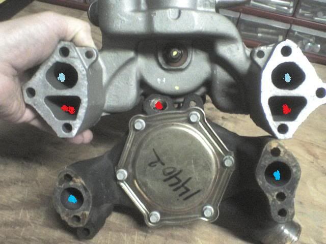
Here is the LT (reverse flow)- I think this is right...please make or post corrections if this is wrong.
Didn't have time to do the Gen 1
Lt1: radiator-lower hose-water pump-head-block-upper hose to radiator.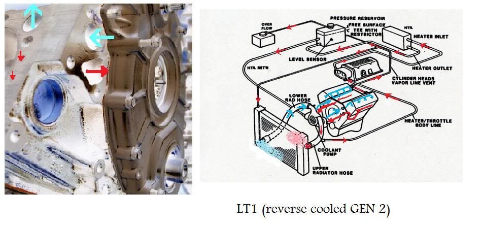
Pumps:

Didn't have time to do the Gen 1
Lt1: radiator-lower hose-water pump-head-block-upper hose to radiator.
Pumps:

 01-10-2011, 09:15 AM
#7
Burning Brakes
Thread Starter
Member Since: Oct 2009
Location: Minneapolis MN
Posts: 773
Likes: 0
Received 0 Likes
on
0 Posts