How To Repair your Range, Miles, etc, button assy
 12-26-2012, 04:54 PM
#1
Heel & Toe

Thread Starter

I had problems with this button assy. I couldn’t reset my oil change light, and some of the buttons ceased to function, or I had to press really hard to get them to work. I couldn’t find anything on getting this assembly fixed or replaced, especially not for cheap. I couldn’t find any repair instructions on this site or on any other….. So after figuring out how to repair it myself, I thought I'd post a "How To" in case anybody else wanted to do the same without spending a mint. I hope this hasn’t been put online someplace cuz this took a while to do.
The problem child
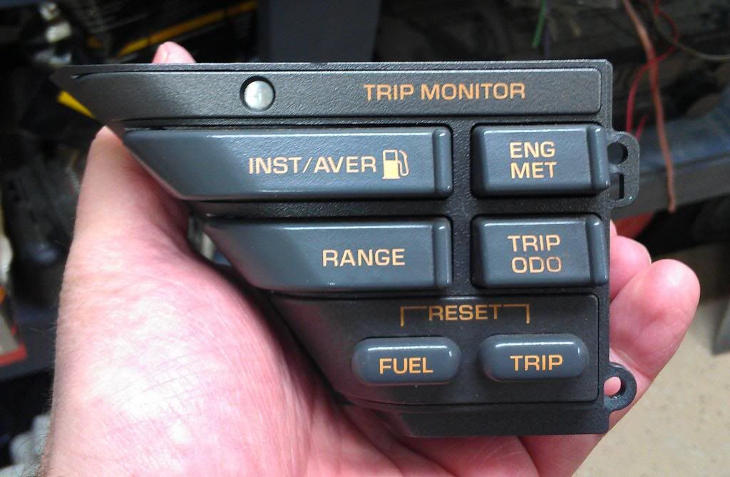
“If” I have to explain how to remove this assy out of the dash, you prolly shouldn’t be trying this repair yourself. Once you have this taken out, turn it over and pull it apart and get to the circuit board.
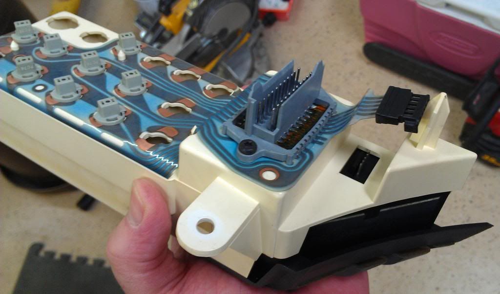
Careful with the connectors, I found mine had a pin bent over by somebody that wasn’t paying attention. This electrical connector was a little bit of a pain to reconnect. The pins wanted to push out of the plastic connector. Also note the missing light bulbs, apparently somebody decided it was easier to remove a trouble light than to fix the problem.
Back of the assy
Cover removed, the PCB or "Circuit board" is held down by some plastic clips around the perimeter.
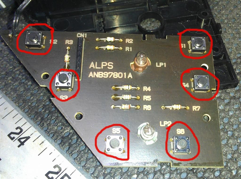
Check out the six little buttons, they call ‘em TACT switches, these are your targets.
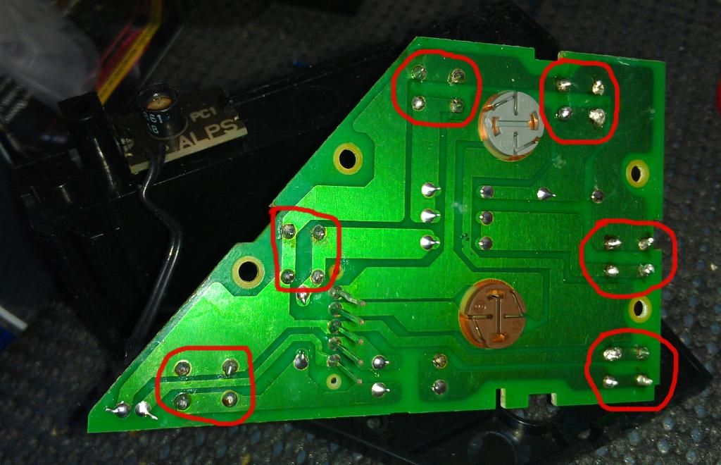
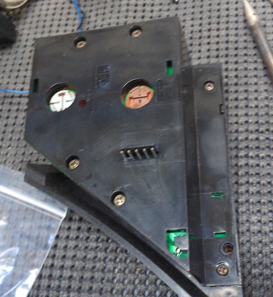
Turn the board over and check out the solder points, It doesn’t look factory because it isn’t. When I took this pic I had already replaced the switches. You can order the switches on Amazon or from many electronics stores. They have 4 pins, and the simple function of the switch is to connect one side of the circuit to the other. The switch installation is dummy proof. There is no way to install them wrong. The distance between the posts makes it so you can’t screw this up. (REALLY….. if it fits in the holes without much force, you have it installed right), If you are not familiar with desoldering and soldering on circuit boards, Check it out on You Tube, it isn’t that hard with a little practice. Take apart any electronic trash, and practice. Buy some desoldering wick, flux, a $10 soldering iron, rosin core solder, and you’re ready to go. Put some flux on the switch’s prongs and then tin them with some solder. Clean the PCB “circuit board” after you remove the old switches and add some flux to the solder connection points. Push the new switch all the way down and solder them back in.
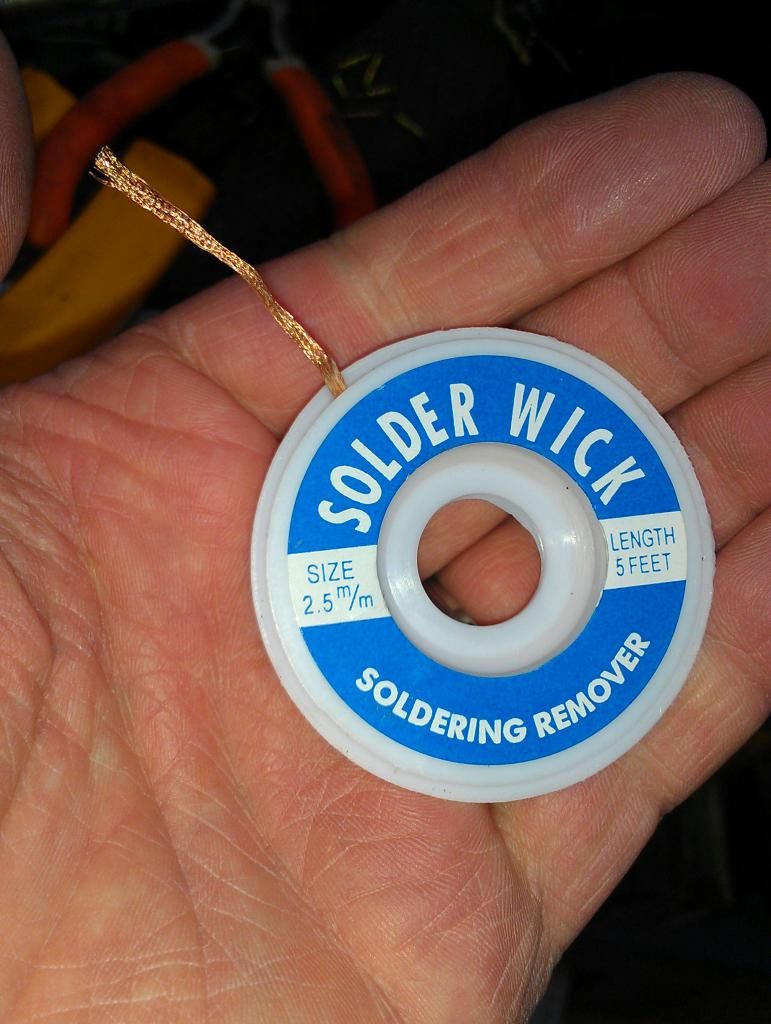
If you have never used this before, look up on U Tube.
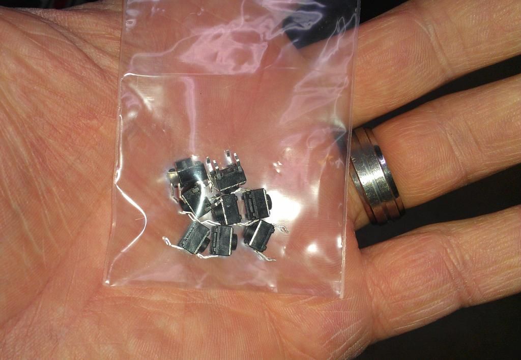
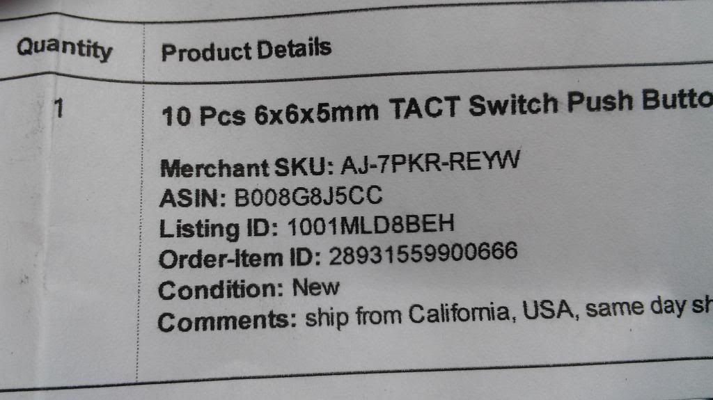
These are the new switches, about $5 with shipping for 10ea on Amazon. Here is a link to the switches I bought on Amazon.
http://www.amazon.com/6x6x5mm-TACT-S...=5336118839-20
If the link doesn't work or is outdated, then do a search for "6x6x5mm TACT switch" and you should be able to find them. The 5mm measurement is how tall it is. The switches are pretty common so this repair could be done on other items that use this style of switch as well. Just measure the bad switch’s Length, Width, and Height in Millimeters and find the same size replacement switch online or at an electronics store.
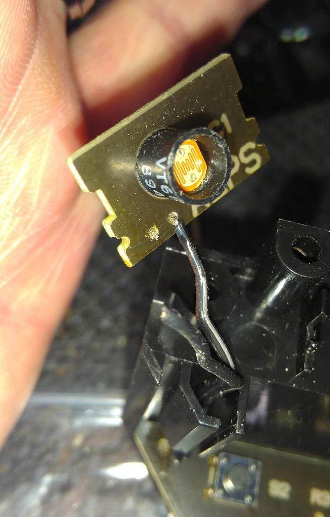
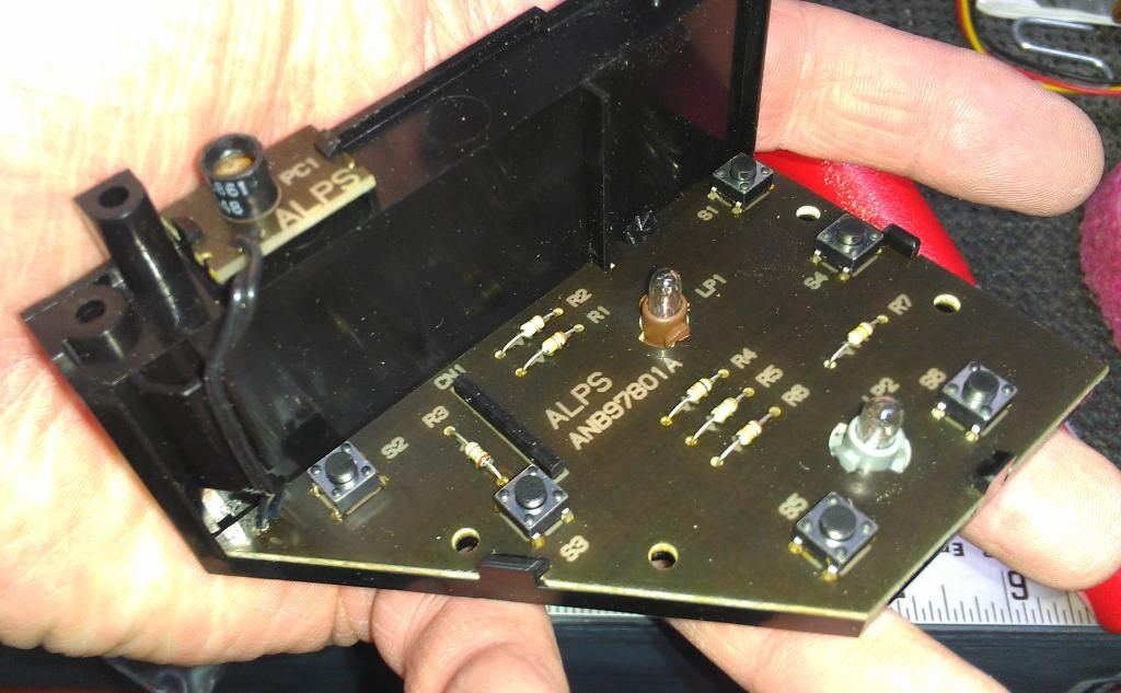
Be careful with the photo sensor wires, they break easy like this one did. If it does, fix it the same way you do the switches.
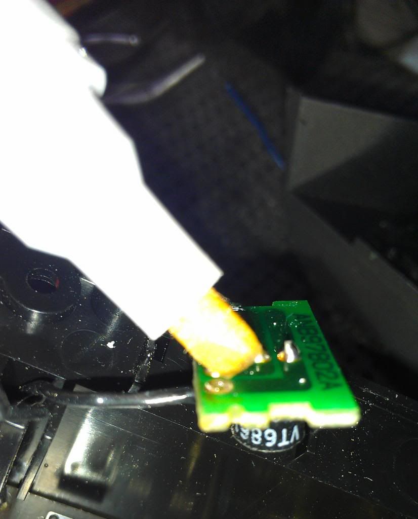
A flux pen is a big help here and on the switch holes. Remember to clean off the flux residue from the board with alcohol or a specialty cleaner after your repair. It's an acid and will eventually damage the components if not removed.
After you solder in your new switches you can test them out with a Voltmeter/Ohm meter
That’s all there is to it! You just saved yourself around $200
Corrections/additions to improve this write-up were made with help from our awesome members comments you will see below.
The problem child
“If” I have to explain how to remove this assy out of the dash, you prolly shouldn’t be trying this repair yourself. Once you have this taken out, turn it over and pull it apart and get to the circuit board.
Careful with the connectors, I found mine had a pin bent over by somebody that wasn’t paying attention. This electrical connector was a little bit of a pain to reconnect. The pins wanted to push out of the plastic connector. Also note the missing light bulbs, apparently somebody decided it was easier to remove a trouble light than to fix the problem.
Back of the assy
Cover removed, the PCB or "Circuit board" is held down by some plastic clips around the perimeter.
Check out the six little buttons, they call ‘em TACT switches, these are your targets.
Turn the board over and check out the solder points, It doesn’t look factory because it isn’t. When I took this pic I had already replaced the switches. You can order the switches on Amazon or from many electronics stores. They have 4 pins, and the simple function of the switch is to connect one side of the circuit to the other. The switch installation is dummy proof. There is no way to install them wrong. The distance between the posts makes it so you can’t screw this up. (REALLY….. if it fits in the holes without much force, you have it installed right), If you are not familiar with desoldering and soldering on circuit boards, Check it out on You Tube, it isn’t that hard with a little practice. Take apart any electronic trash, and practice. Buy some desoldering wick, flux, a $10 soldering iron, rosin core solder, and you’re ready to go. Put some flux on the switch’s prongs and then tin them with some solder. Clean the PCB “circuit board” after you remove the old switches and add some flux to the solder connection points. Push the new switch all the way down and solder them back in.
If you have never used this before, look up on U Tube.
These are the new switches, about $5 with shipping for 10ea on Amazon. Here is a link to the switches I bought on Amazon.
http://www.amazon.com/6x6x5mm-TACT-S...=5336118839-20
If the link doesn't work or is outdated, then do a search for "6x6x5mm TACT switch" and you should be able to find them. The 5mm measurement is how tall it is. The switches are pretty common so this repair could be done on other items that use this style of switch as well. Just measure the bad switch’s Length, Width, and Height in Millimeters and find the same size replacement switch online or at an electronics store.
Be careful with the photo sensor wires, they break easy like this one did. If it does, fix it the same way you do the switches.
A flux pen is a big help here and on the switch holes. Remember to clean off the flux residue from the board with alcohol or a specialty cleaner after your repair. It's an acid and will eventually damage the components if not removed.
After you solder in your new switches you can test them out with a Voltmeter/Ohm meter
That’s all there is to it! You just saved yourself around $200
Corrections/additions to improve this write-up were made with help from our awesome members comments you will see below.
Last edited by Spharticus; 01-04-2013 at 04:57 PM. Reason: Corrections, updates, spelling, grammar

The following 2 users liked this post by Spharticus:
C4ProjectCar (01-27-2020),
xrav22 (02-16-2019)
 12-26-2012, 06:51 PM
#3
Safety Car

Member Since: Mar 2005
Location: Fredonia WI
Posts: 3,566
Received 491 Likes
on
392 Posts
2023 C4 of the Year Finalist- Modified
Finalist 2020 C4 of the Year - Modified
C4 of Year Finalist (performance mods) 2019
2018 C4 of Year Finalist

Very nice write up. Thanks for posting this.
It was especially helpful to have the source of the switches listed.

It was especially helpful to have the source of the switches listed.
Last edited by ghlkal; 12-26-2012 at 07:13 PM.
12-26-2012, 07:09 PM
#4


great info & write-up - 
12-26-2012, 08:20 PM
#6

Good right up!
I just want to add a point about using the Flux Pen. After soldering with the flux pen please clean the PCB with Flux Off or isopropyl alcohol.
The flux pens can leave a corrosive residue if you don't clean it off!
I am in the electronics industry and we do use flux pens but always follow it up by a cleaning.
12-26-2012, 09:39 PM
#7
Heel & Toe
Thread Starter
Good right up!
I just want to add a point about using the Flux Pen. After soldering with the flux pen please clean the PCB with Flux Off or isopropyl alcohol.
The flux pens can leave a corrosive residue if you don't clean it off!
I am in the electronics industry and we do use flux pens but always follow it up by a cleaning.
I just want to add a point about using the Flux Pen. After soldering with the flux pen please clean the PCB with Flux Off or isopropyl alcohol.
The flux pens can leave a corrosive residue if you don't clean it off!
I am in the electronics industry and we do use flux pens but always follow it up by a cleaning.
12-26-2012, 10:27 PM
#8
Le Mans Master

Thanks for the information. Just the part number is worth is worth it's weight in gold.
Sometimes lamps are left out depending on some options the car may have. I believe I have some lamps not installed but have not had it out in 7+ years.
Sometimes lamps are left out depending on some options the car may have. I believe I have some lamps not installed but have not had it out in 7+ years.
12-26-2012, 10:47 PM
#9
Heel & Toe
Thread Starter
To be honest I did this whole writup after a few "cold ones".
 12-26-2012, 11:33 PM
#10
Team Owner

Pro Mechanic
Awesome post! Thanks for the time, pics and explanation! 

 01-02-2013, 09:31 PM
#12
Burning Brakes


Thank you for taking the time to photograph the steps and put this all together. Very well done.
GOOD JOB!!
They oughta make this a "sticky".
GOOD JOB!!
They oughta make this a "sticky".
Last edited by j-wireman; 01-02-2013 at 09:55 PM.
01-03-2013, 10:08 AM
#13
Heel & Toe
Thread Starter
Thanks guys! I updated the write-up to fix some spelling and other stuff (I blame the beer..lol.) and updated it with your awesome suggestions/tips so others will get a more complete write-up.
 01-04-2013, 04:28 PM
#17
Heel & Toe
Thread Starter
I do use rosin core solder, and you can skip using a flux pen if you use proper soldering methods. I dont use flux pens if all I'm doing is soldering some wires together. But on circuit boards (PCB's) I find using flux pens on parts beforehand makes life a lot easier for me. I guess it compensates for my lack of small parts soldering skills. HAHA. I'll link a video and you'll see how he says do not add the solder to the iron before touching the joint, because it burns off the flux and you won’t get a good solder joint. I find if you use the flux pen on parts first, the oxidation will already be cleaned off before adding the heat and solder and makes everything flow fast and easy without having to overheat the parts and I get a good solder joint the first time almost every time. If you look close at the picture of my soldering job, you’ll see some of the connections don’t look that awesome. Those are the ones I did before I remembered that I had a flux pen and started using it. But by all means use what works for you. =)
https://www.youtube.com/watch?v=I_NU2ruzyc4
And here is another video. It's 30 years old, but not much has changed.
https://www.youtube.com/watch?v=vIT4...ture=endscreen
https://www.youtube.com/watch?v=I_NU2ruzyc4
And here is another video. It's 30 years old, but not much has changed.
https://www.youtube.com/watch?v=vIT4...ture=endscreen
Last edited by Spharticus; 01-04-2013 at 05:00 PM. Reason: word correction
01-31-2013, 09:14 AM
#18

You did such a great job at explaining how to replace those buttons that im going to do it when i get home...and mine work just fine!! Only kidding i have enough other things to do! Dave
01-31-2013, 10:00 AM
#19
Heel & Toe
Thread Starter
 I'm currently pulling the motor and trans out of my car to do a rebuild and give it some mild upgrades. I don't trust throwing a 100+ shot of NOS on a motor and trans that has 185,000 miles on it.
  04-26-2013, 02:33 PM
#20
Le Mans Master

Just did this yesterday and it fixed all my problems!
A word of caution - the traces can lift easily if the holes aren't clear and you poke the leads for the new switches through.
A word of caution - the traces can lift easily if the holes aren't clear and you poke the leads for the new switches through.