Question on Engine Coolant Temp Sensor in my 84
 11-19-2014, 07:18 PM
#1
Advanced

Thread Starter

Member Since: Oct 2014
Location: Brisbane
Posts: 74
Likes: 0
Received 0 Likes
on
0 Posts
Hi guys,
So, I've been having problems with my 84 running rough when it reaches around 195F and some of the good people on this forum suggested changing the Engine Coolant Temp sensor in the front of the intake. I understand the ECT lets the ECM know when the car is at temp and adjusts fuel mixutures etc. I changed the sensor, but unfortunately it has not resolved my problem once the car reaches temp.
So, on removing the sensor, it was apparent that the original sensor has previously been replaced with a later version. As I understand it, the original only has one wire going to it, whereas the plug on this one has two. The wiring for the plug seems to be contained within this loom
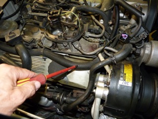
So, before I start stripping the loom back to find out where the wires are connected to, can anyone confirm whether the original has only one wire, and if so, has anyone wired up one of the new or replacement sender plug connectors with the two wires and where do they go to?
Thanks in advance for your help guys.
So, I've been having problems with my 84 running rough when it reaches around 195F and some of the good people on this forum suggested changing the Engine Coolant Temp sensor in the front of the intake. I understand the ECT lets the ECM know when the car is at temp and adjusts fuel mixutures etc. I changed the sensor, but unfortunately it has not resolved my problem once the car reaches temp.
So, on removing the sensor, it was apparent that the original sensor has previously been replaced with a later version. As I understand it, the original only has one wire going to it, whereas the plug on this one has two. The wiring for the plug seems to be contained within this loom
So, before I start stripping the loom back to find out where the wires are connected to, can anyone confirm whether the original has only one wire, and if so, has anyone wired up one of the new or replacement sender plug connectors with the two wires and where do they go to?
Thanks in advance for your help guys.
 11-19-2014, 07:44 PM
#2


The original one should have 2 wires going to the sensor also. A 5v reference goes to the sensor & the ecm reads the voltage difference after it goes through the sensor. The original sensors & connectors were troublesome.
11-19-2014, 09:30 PM
#3
Safety Car


Have you ordered your Factory Shop Manual yet? I don't know how you can keep a 30 year old car as complex as your 'vette in good shape without one! Don't waste your money on the Haynes or Chilton's.
My '84 FSM shows the original sensor has two wires, yellow and black. The black connects to ground, and the yellow goes to the ECM, pin 4. There is no +5 reference voltage, just these two wires.
You are looking at the right sensor? It's located behind the drive belt idler spring loaded pivot thingie.
Are you sure you don't have any vacuum leaks? Check the 16 bolts around your throttle body mounting plate. After the car has been sitting for a few hours, pull the vacuum line that goes to the ball shaped vacuum reservoir in the left front fender well. You should still have vacuum on this line!
Last edited by Hot Rod Roy; 11-19-2014 at 09:41 PM.
11-20-2014, 02:36 AM
#4
Race Director

The ECM supplies a 5 volt reference voltage through a precision resistor on the yellow wire. The coolant temperature sensor acts as a voltage divider and the ECM measures the voltage and derives the coolant temperature from that by using a lookup table.
11-20-2014, 03:07 AM
#5
Safety Car
Au contraire, mon ami.
The ECM supplies a 5 volt reference voltage through a precision resistor on the yellow wire. The coolant temperature sensor acts as a voltage divider and the ECM measures the voltage and derives the coolant temperature from that by using a lookup table.
The ECM supplies a 5 volt reference voltage through a precision resistor on the yellow wire. The coolant temperature sensor acts as a voltage divider and the ECM measures the voltage and derives the coolant temperature from that by using a lookup table.
I think this is more information than 70chevy asked about, or needs to know. He only asked, one wire or two?
Last edited by Hot Rod Roy; 11-20-2014 at 03:16 AM.
11-20-2014, 03:20 AM
#6


Hi guys,
So, I've been having problems with my 84 running rough when it reaches around 195F and some of the good people on this forum suggested changing the Engine Coolant Temp sensor in the front of the intake. I understand the ECT lets the ECM know when the car is at temp and adjusts fuel mixutures etc. I changed the sensor, but unfortunately it has not resolved my problem once the car reaches temp.
So, on removing the sensor, it was apparent that the original sensor has previously been replaced with a later version. As I understand it, the original only has one wire going to it, whereas the plug on this one has two. The wiring for the plug seems to be contained within this loom
Attachment 47842054
So, before I start stripping the loom back to find out where the wires are connected to, can anyone confirm whether the original has only one wire, and if so, has anyone wired up one of the new or replacement sender plug connectors with the two wires and where do they go to?
Thanks in advance for your help guys.
You are correct in that the original was a single pin sensor and the original part number would have been GM/ACD 25036092. That was later serviced by a package that contained both the 2 pin sensor and the appropriate connector. GM/ACD service part I believe would have been 10045847. That part number I believe is still active. If yours is already converted that would have been an appropriate repair.
The first service part number for the 2 pin would have been I'm quite sure would have been GM/ACD 25036979 and later either of these 12146312 or 15326386 if you only need the sensor. Buy either of those or the equivalent if you need only the sensor.
Last edited by WVZR-1; 11-20-2014 at 03:29 AM.
11-20-2014, 08:49 PM
#7
Advanced
Thread Starter
Member Since: Oct 2014
Location: Brisbane
Posts: 74
Likes: 0
Received 0 Likes
on
0 Posts
You are correct in that the original was a single pin sensor and the original part number would have been GM/ACD 25036092. That was later serviced by a package that contained both the 2 pin sensor and the appropriate connector. GM/ACD service part I believe would have been 10045847. That part number I believe is still active. If yours is already converted that would have been an appropriate repair.
The first service part number for the 2 pin would have been I'm quite sure would have been GM/ACD 25036979 and later either of these 12146312 or 15326386 if you only need the sensor. Buy either of those or the equivalent if you need only the sensor.
The first service part number for the 2 pin would have been I'm quite sure would have been GM/ACD 25036979 and later either of these 12146312 or 15326386 if you only need the sensor. Buy either of those or the equivalent if you need only the sensor.
11-20-2014, 08:50 PM
#8
Advanced
Thread Starter
Member Since: Oct 2014
Location: Brisbane
Posts: 74
Likes: 0
Received 0 Likes
on
0 Posts
Guys,
Thank you for your help so far. I appreciate it.
So, now that I've replaced the sensor, the car still runs rough once it reaches approx 190 degrees f. Do any of you guys have experience with similar problems, or can you suggest where I look next for the problem?
Just a reminder that I'm located in Australia and C4 Corvette experts, let along 1984 Cross Fire Injection experts are pretty scarce so I appreciate any help you can offer.
Thank you.
Darren
11-21-2014, 01:50 AM
#9
Race Director
Cliff, guess I'm misunderstanding something here. Please explain how you can have a voltage divider and a measurement of the sensed temperature with only two wires. My book shows the black wire to ground, and the yellow to the ECM. Where is the 5 volt reference voltage? Maybe so, inside the ECM, but that's not accessable without getting inside the ECM, and therefore it's not testable (is that a word?). My book shows the sensor as a variable resistor, not a voltage divider. Voltage dividers typically require three wires.
11-21-2014, 01:57 AM
#10
Race Director
I suggest that you get a ALDL cable and connect up to a computer with scan software to find out exactly what the ECM is seeing. TunerPro software is free, so you could find out what your car is doing for the cost of a cable. The cable I have cost 70 dollars US. I have had it quite a while so they might be available now for less money.
11-21-2014, 07:30 AM
#11
Advanced
Thread Starter
Member Since: Oct 2014
Location: Brisbane
Posts: 74
Likes: 0
Received 0 Likes
on
0 Posts
It sounds like it's going bad when it gets into closed loop mode. That is when the ECM uses the O2 sensor to adjust the air/fuel ratio. A bad O2 sensor or a bad connection might cause your problem.
I suggest that you get a ALDL cable and connect up to a computer with scan software to find out exactly what the ECM is seeing. TunerPro software is free, so you could find out what your car is doing for the cost of a cable. The cable I have cost 70 dollars US. I have had it quite a while so they might be available now for less money.
I suggest that you get a ALDL cable and connect up to a computer with scan software to find out exactly what the ECM is seeing. TunerPro software is free, so you could find out what your car is doing for the cost of a cable. The cable I have cost 70 dollars US. I have had it quite a while so they might be available now for less money.
Thank you again for the invaluable help. I have had a look at the O2 sensor and it looks new. I know that doesn't mean anything, but other than scanning the ECM, is it possible to unplug it, or the ECT or something like that to try to narrow this down. Alternatively, is pulling the codes by using the paper clip method in the ALDL ports the same as what you're suggesting with a scanner? Again, I appreciate your help.
I'll keep sneaking up on this problem and will eventually fix it if it kills me. It is the only think really stopping me from fully enjoying this car at the moment, but I am enjoying the challenge.
Thanks
Darren
11-21-2014, 08:55 PM
#12

Hi guys,
So, I've been having problems with my 84 running rough when it reaches around 195F and some of the good people on this forum suggested changing the Engine Coolant Temp sensor in the front of the intake. I understand the ECT lets the ECM know when the car is at temp and adjusts fuel mixutures etc. I changed the sensor, but unfortunately it has not resolved my problem once the car reaches temp.
So, on removing the sensor, it was apparent that the original sensor has previously been replaced with a later version. As I understand it, the original only has one wire going to it, whereas the plug on this one has two. The wiring for the plug seems to be contained within this loom
Attachment 47842054
So, before I start stripping the loom back to find out where the wires are connected to, can anyone confirm whether the original has only one wire, and if so, has anyone wired up one of the new or replacement sender plug connectors with the two wires and where do they go to?
Thanks in advance for your help guys.
So, I've been having problems with my 84 running rough when it reaches around 195F and some of the good people on this forum suggested changing the Engine Coolant Temp sensor in the front of the intake. I understand the ECT lets the ECM know when the car is at temp and adjusts fuel mixutures etc. I changed the sensor, but unfortunately it has not resolved my problem once the car reaches temp.
So, on removing the sensor, it was apparent that the original sensor has previously been replaced with a later version. As I understand it, the original only has one wire going to it, whereas the plug on this one has two. The wiring for the plug seems to be contained within this loom
Attachment 47842054
So, before I start stripping the loom back to find out where the wires are connected to, can anyone confirm whether the original has only one wire, and if so, has anyone wired up one of the new or replacement sender plug connectors with the two wires and where do they go to?
Thanks in advance for your help guys.
https://www.corvetteforum.com/forums...or-to-ecm.html
I upgraded to the new type, though my connector was a white wire and black wire. So i connected the white to the yellow, and the black to black. Haven't had any issues.
11-21-2014, 10:21 PM
#13
Yes the original is a 2 wire, BUT it looks exactly like the temp fan switch connector which is one wire, the original 2 wire connector is impossible to find. You can see in my thread below what i went through.
https://www.corvetteforum.com/forums...or-to-ecm.html
I upgraded to the new type, though my connector was a white wire and black wire. So i connected the white to the yellow, and the black to black. Haven't had any issues.
https://www.corvetteforum.com/forums...or-to-ecm.html
I upgraded to the new type, though my connector was a white wire and black wire. So i connected the white to the yellow, and the black to black. Haven't had any issues.
There were two connectors that would fit the correct sensor, the difference was only an extended tip for the center pin:
The extended tipped one GM 12026621 and the standard one GM 12014843. Both are on eBay regularly and there are I believe other sources. These fit CTS for all early GM's.
GOOGLE IMAGES will display both.
Last edited by WVZR-1; 11-21-2014 at 11:56 PM.
06-29-2015, 12:31 AM
#14
Advanced
Thread Starter
Member Since: Oct 2014
Location: Brisbane
Posts: 74
Likes: 0
Received 0 Likes
on
0 Posts
Cliff,
Thank you again for the invaluable help. I have had a look at the O2 sensor and it looks new. I know that doesn't mean anything, but other than scanning the ECM, is it possible to unplug it, or the ECT or something like that to try to narrow this down. Alternatively, is pulling the codes by using the paper clip method in the ALDL ports the same as what you're suggesting with a scanner? Again, I appreciate your help.
I'll keep sneaking up on this problem and will eventually fix it if it kills me. It is the only think really stopping me from fully enjoying this car at the moment, but I am enjoying the challenge.
Thanks
Darren
Haven't touched this one in a while, but am ready to get back to it. In order for me to fix this, I guess I need to understand what is happening in the car, so would appreciate it if someone can explain.
I understand that when the car is first started and is cold, it runs in "open loop". What exactly does that mean? Is it rich or lean etc. Once it reaches temp, I understand it switches to "closed loop". Again, what does that mean. How do the CTS and the O2 sensors along with the ECU play a part in this?
I'm keen to fix it and to do that, I kinda need to understand how this all works. A reminder that it's an 84 original crossfire with no mods and yes, I have an FSM.
Thanks in advance.
Darren
06-30-2015, 01:09 PM
#15
Racer
G'day guys,
Haven't touched this one in a while, but am ready to get back to it. In order for me to fix this, I guess I need to understand what is happening in the car, so would appreciate it if someone can explain.
I understand that when the car is first started and is cold, it runs in "open loop". What exactly does that mean? Is it rich or lean etc. Once it reaches temp, I understand it switches to "closed loop". Again, what does that mean. How do the CTS and the O2 sensors along with the ECU play a part in this?
I'm keen to fix it and to do that, I kinda need to understand how this all works. A reminder that it's an 84 original crossfire with no mods and yes, I have an FSM.
Thanks in advance.
Darren
Here's a start for ya. This article strikes a nice balance between conciseness and detail. Lots more to be found on Google

http://www.obdii.com/articles/Unders...n_Sensors.html
Last edited by 84Z51J; 06-30-2015 at 01:14 PM.
07-01-2015, 12:14 AM
#16
Race Director
Here's a start for ya. This article strikes a nice balance between conciseness and detail. Lots more to be found on Google
http://www.obdii.com/articles/Unders...n_Sensors.html
http://www.obdii.com/articles/Unders...n_Sensors.html
07-01-2015, 06:58 AM
#17
You know if you do the paper clip trick to the scanner connector & start up the car, the CEL will start flashing, this tells you the o2 activity. Make sure you do this after you warm it up.
07-01-2015, 07:49 PM
#18
Advanced
Thread Starter
Member Since: Oct 2014
Location: Brisbane
Posts: 74
Likes: 0
Received 0 Likes
on
0 Posts
Thanks 84Z51J very much for the article. Very easy to understand. So, from what I'm reading there, my car starts and runs ok whilst it is in open loop (rich). I take it that the coolant temp sensor must be working as when the car reaches temp of approx 195 it starts to run rough. That would indicate that it is telling the ECU that it has reached the required temp to transition into closed loop, as it only does this at that temp or higher. If the CTS wasn't working, why would it change at this temp? Am I correct so far?
So, if the CTS is working properly, the car tries to go into closed loop and lean out the fuel mixture. Something is going wrong at that time. So, it could either be that once the engine is at the required operating temp, the O2 sensor is faulty and sending incorrect data to the ECU, or the o2 sensor is working oK and the ECU is faulty and isn't doing what it should be doing once receiving the data from the O2 sensor? Is that also correct?
So, I should be looking at trying to see if the 02 sensor is working properly, and if so it's then down to the ECU which I expect is a remove and replace job on an 84.
So, without a scan tool, I expect the only way to test the O2 sensor is to replace it? The O2 sensor in the car looks new so I think the previous owner has chased this problem as well, but not had any luck.
By the way, when I run the car with the cooling fan on and it sits below 195 I have no problem, except the fuel consumption.
ex-ex, I will do the paper clip trick and read the results, I have a page printed on that, but what would I look for which might indicate a problem with the O2 sensor.
Guys, I genuinely appreciate your help and am determined to get this fixed as I don't like having something not working correctly on my beautiful Corvette. Well, it's beautiful to me.
Thanks again.
Darren
07-02-2015, 04:19 AM
#19
Advanced
Thread Starter
Member Since: Oct 2014
Location: Brisbane
Posts: 74
Likes: 0
Received 0 Likes
on
0 Posts
OK, so further to my last post, I just tested the car using the paper clip method. No error codes when cold. No surprises. Took the car for a drive, got it up to temp and it started playing up once it reached temps. Got home, did the paper clip test and again no error codes. Does this narrow the problem down to the ECU maybe??
Thanks again, I look forward to your collective wisdom and advice.
Darren
Thanks again, I look forward to your collective wisdom and advice.
Darren