1992 LT1-no start due to short to IC circuit 423. How to find the short?
 05-22-2015, 03:52 PM
#1
Instructor

Thread Starter
Used the FSM to determine why the car set a DTC 41. I have voltage to "B"(white wire) on ICM harness. Way too much! The FSM asks if there is at least .5 volts and there is almost 11 volts! I think it's safe to say that this is why the DTC 41 is being set. Checked "A" (black/red) from Opti to ECM and had proper voltage, eliminating the ECM as the problem. What it comes down to for me is, where and why is the voltage so high to the ICM, and how do I fix it? The FSM is unclear about the procedure under these circumstances. Ideas? Thanks Forum!
 05-22-2015, 06:34 PM
#2
Melting Slicks


Member Since: Aug 1999
Location: Baltimore, MD USA
Posts: 2,240
Likes: 0
Received 34 Likes
on
30 Posts

Used the FSM to determine why the car set a DTC 41. I have voltage to "B"(white wire) on ICM harness. Way too much! The FSM asks if there is at least .5 volts and there is almost 11 volts! I think it's safe to say that this is why the DTC 41 is being set. Checked "A" (black/red) from Opti to ECM and had proper voltage, eliminating the ECM as the problem. What it comes down to for me is, where and why is the voltage so high to the ICM, and how do I fix it? The FSM is unclear about the procedure under these circumstances. Ideas? Thanks Forum!
Ignition On.
With a Voltmeter set to DC one probe to ground and the other
probe to Pin B on the connector (White wire) you should measure
no more than .5 volts DC.
You said you measure 11 volts DC?
If that's true they say to turn the ignition Off.
Unplug the Gray connector at the ECM.
Turn the ignition On verify the voltage is zero on the White wire.
If there is any voltage on the White wire the wire is shorted to another power source.
If you measure zero volts the ECM is the problem and where the 11 volts is coming from.
05-22-2015, 08:05 PM
#3
Instructor
Thread Starter
You disconnect the plug at the ignition control module.
Ignition On.
With a Voltmeter set to DC one probe to ground and the other
probe to Pin B on the connector (White wire) you should measure
no more than .5 volts DC.
You said you measure 11 volts DC?
If that's true they say to turn the ignition Off.
Unplug the Gray connector at the ECM.
Turn the ignition On verify the voltage is zero on the White wire.
If there is any voltage on the White wire the wire is shorted to another power source.
If you measure zero volts the ECM is the problem and where the 11 volts is coming from.
05-22-2015, 08:53 PM
#4
Melting Slicks
Member Since: Aug 1999
Location: Baltimore, MD USA
Posts: 2,240
Likes: 0
Received 34 Likes
on
30 Posts
It can't be the Prom.
You turn the ignition On and measure the voltage on the White wire circuit 423 at Pin B of the ignition control module.
The voltage should be less than .5 volts DC
If the voltage is less than .5 volts DC you change the meter to read AC.
Crank the engine and the meter should read a changing
1 to 4 volts AC.
That is normal.
If when you turn the ignition on and you read 11 volts DC
that's bad news.
To find out where the 11 volts is coming from you disconnect the
4 pin connector at the ignition control module.
Turn the ignition On.
If you still read 11 volts DC on the White wire you disconnect the gray connector
at the ECM.
If you still read 11 volts DC the White wire is shorted to a voltage source and that is where the 11 volts is coming from.
If you read zero volts on the White wire the problem is the ECM.
Last edited by Hooked on Vettes; 05-22-2015 at 08:58 PM.
05-23-2015, 09:36 AM
#5
Instructor
Thread Starter
It can't be the Prom.
You turn the ignition On and measure the voltage on the White wire circuit 423 at Pin B of the ignition control module.
The voltage should be less than .5 volts DC
If the voltage is less than .5 volts DC you change the meter to read AC.
Crank the engine and the meter should read a changing
1 to 4 volts AC.
That is normal.
If when you turn the ignition on and you read 11 volts DC
that's bad news.
To find out where the 11 volts is coming from you disconnect the
4 pin connector at the ignition control module.
Turn the ignition On.
If you still read 11 volts DC on the White wire you disconnect the gray connector
at the ECM.
If you still read 11 volts DC the White wire is shorted to a voltage source and that is where the 11 volts is coming from.
If you read zero volts on the White wire the problem is the ECM.
You turn the ignition On and measure the voltage on the White wire circuit 423 at Pin B of the ignition control module.
The voltage should be less than .5 volts DC
If the voltage is less than .5 volts DC you change the meter to read AC.
Crank the engine and the meter should read a changing
1 to 4 volts AC.
That is normal.
If when you turn the ignition on and you read 11 volts DC
that's bad news.
To find out where the 11 volts is coming from you disconnect the
4 pin connector at the ignition control module.
Turn the ignition On.
If you still read 11 volts DC on the White wire you disconnect the gray connector
at the ECM.
If you still read 11 volts DC the White wire is shorted to a voltage source and that is where the 11 volts is coming from.
If you read zero volts on the White wire the problem is the ECM.
Last edited by Den14; 05-23-2015 at 09:39 AM.
05-23-2015, 10:37 AM
#6
Melting Slicks
Member Since: Aug 1999
Location: Baltimore, MD USA
Posts: 2,240
Likes: 0
Received 34 Likes
on
30 Posts
With the ECM Gray plug still disconnected.
Now disconnect the four pin ICM connector plug.
With ignition On you should measure zero volts on Pin B White wire on the disconnected
end of the wire harness plug. NOT PIN B on the ICM.
That's normal. Both wires will be around 12 volts with ignition On.
If both the ICM plug and Gray ECM plug are disconnected and you still have 11 volts on the Pin B White wire in the harness. Yes something is wrong and the White wire is shorted to a power source.
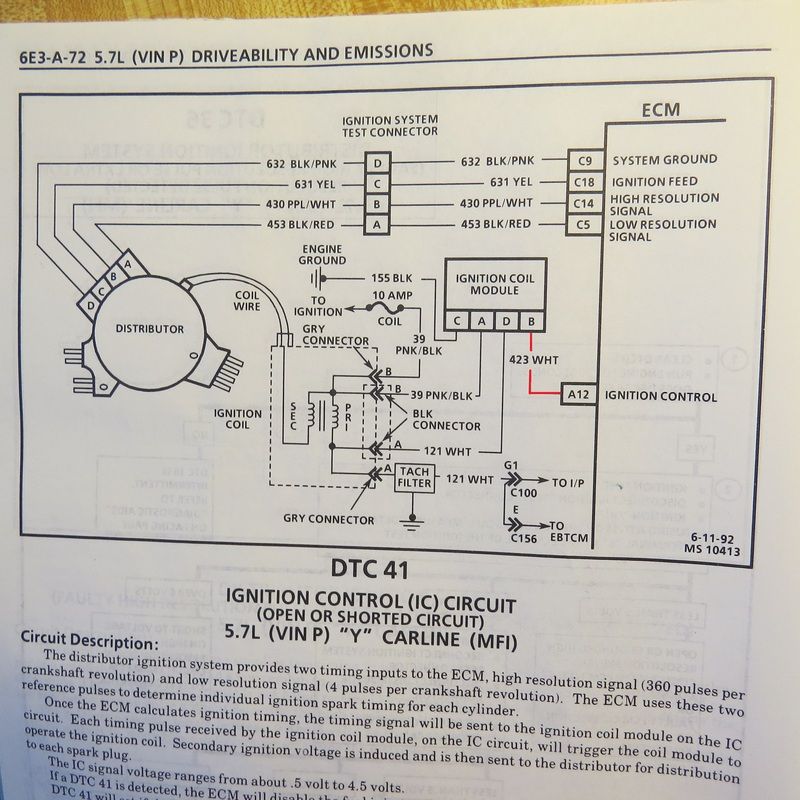
Here's the schematic.
The Ignition Control Module has a 4 pin connector.
Pin A Pink/Black wire. (With ignition On will have 12 volts).
Pin B White wire is the one you say has 11 volts on it and goes to ECM pin A12. This is the signal from the ECM to the ICM to control the coil and should have less than .5 volts DC on it with the ignition On.
Pin C Black wire is Ground.
Pin D White wire is the control wire the Ignition Control Module grounds to fire the coil and will measure around 12 volts with the ignition On.
If you unplug the Gray connector at the ECM and turn the ignition On and still have 11 volts on Pin B White wire while the ICM plug is still connected to the ICM either the ICM is bad or the 11 volts is coming from the White wire.
To verify that you disconnect the Ignition Control Module 4 pin connector and with one probe to ground and the other probe on Pin B White wire of the disconnect plug you should read zero volts because both ends of the cable are disconnected.
If you read 11 volts the White wire is getting voltage from another source so you need to trace the Pin B White wire and see where it's shorted to another wire some where in the harness.
If you measure zero volts the ICM is bad.
If you replace the ICM make sure you coat the backside of the ICM with heat sink compound.
Some may come with the new ICM. If not you can purchase a small tube of it from Radio Shack. It's called heat sink compound or thermal paste.

Last edited by Hooked on Vettes; 05-23-2015 at 01:57 PM.
05-23-2015, 11:10 AM
#7
Instructor
Thread Starter
Not good but that eliminates the ECM.
With the ECM Gray plug still disconnected.
Now disconnect the four pin ICM connector plug.
With ignition On you should measure zero volts on Pin B White wire on the disconnected
end of the wire harness plug. NOT PIN B on the ICM.
That's normal. Both wires will be around 12 volts with ignition On.
If the ICM plug disconnected and the ECM Gray plug disconnected and you still have 11 volts on the Pin B whiter wire in the harness. Yes something is wrong and the White wire is shorted to a power source.
Here's the schematic.
The Ignition Control Module has a 4 pin connector.
Pin A Pink/Black wire. (With ignition On will have 12 volts).
Pin B White wire is the one you say has 11 volts on it and goes to ECM pin A12. This is the signal from the ECM to the ICM to control the coil.
This is the wire that should have less than .5 volts DC on it with the ignition On.
Pin C Black wire is Ground.
Pin D White wire is the control wire the Ignition Control Module grounds to fire the coil and will measure around 12 volts with the ignition On.
If you unplugged the Gray connector at the ECM and turn the ignition On and still have 11 volts on Pin B White wire while the ICM plug is still connected to the ICM I'd say the Ignition Control Module is bad and is where the 11 volts is coming from.
To verify that you disconnect the Ignition Control Module 4 pin connector and with one probe to ground and the other probe on Pin B White wire of the disconnect plug you should read zero volts because both ends of the cable are disconnected.
If you read 11 volts the White wire is getting voltage from another source so you need to trace the Pin B White wire and see where it's shorted to another wire some where in the harnesss.
05-23-2015, 11:12 AM
#8
Instructor
Thread Starter
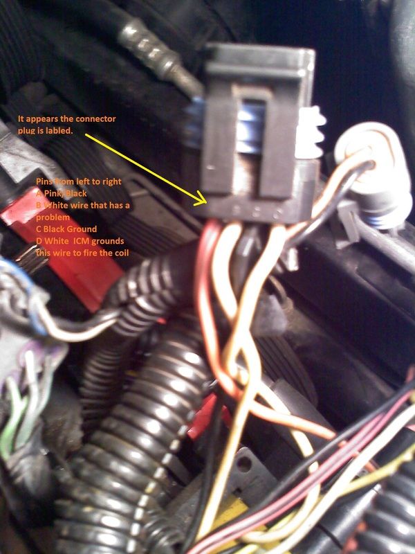
Thanks for the schematic. I have the FSM. What is confusing me is the wire colors. Looking at the connector that goes to the ICM, the color of the wires in this sequence ( I will load a photo) pink/black, white, black, white. I am confused by the FSM schematic showing the order as pink/black, pink/black, white, white. Am I testing the connector for the correct voltage or should I be testing somewhere other than the ICM 4-pin connector? As far as the A12 connection, is that contained in the grey ECM plug I disconnected to check the voltage at the 4-pin plug? I am plainly confused at the moment. Thank you for helping to clarify this for me. The wire colors has me wondering if I am even testing the right circuits. From the pink/black and white wires they just go to the coil plugs. I must not be in the right location.
05-23-2015, 11:38 AM
#9
Melting Slicks
Member Since: Aug 1999
Location: Baltimore, MD USA
Posts: 2,240
Likes: 0
Received 34 Likes
on
30 Posts
It appears the connector has the pin out etched into the connector.
The schematic can be confusing because it's drawn for convenience so the drawing looks nice and neat. The actual connector pin outs of the connector are in sequence ABCDE.
The most probably cause for the 11 volt problem is the ICM but to verify you need to disconnect the ECM Gray plug and the ICM plug and with the ignition On verify you have zero volts on the Pin B White wire of the harness plug. (Not at the ICM Pin B). If that's correct the
11 volts must be coming from the ICM which indicates its bad.

Last edited by Hooked on Vettes; 05-23-2015 at 02:02 PM.
05-23-2015, 04:13 PM
#10
Instructor
Thread Starter
It appears the connector has the pin out etched into the connector.
The schematic can be confusing because it's drawn for convenience so the drawing looks nice and neat. The actual connector pin outs of the connector are in sequence ABCDE.
The most probably cause for the 11 volt problem is the ICM but to verify you need to disconnect the ECM Gray plug and the ICM plug and with the ignition On verify you have zero volts on the Pin B White wire of the harness plug. (Not at the ICM Pin B). If that's correct the
11 volts must be coming from the ICM which indicates its bad.
The schematic can be confusing because it's drawn for convenience so the drawing looks nice and neat. The actual connector pin outs of the connector are in sequence ABCDE.
The most probably cause for the 11 volt problem is the ICM but to verify you need to disconnect the ECM Gray plug and the ICM plug and with the ignition On verify you have zero volts on the Pin B White wire of the harness plug. (Not at the ICM Pin B). If that's correct the
11 volts must be coming from the ICM which indicates its bad.
 02-05-2018, 06:16 AM
#12
Intermediate

Hi Hooked Vettes ,Den 14,
I wake up one old thread ,form 2015 ,about this problem ,because it's 100 % the problem I have .So can you tell me what is PCM ,(is it same as ECM ?) ,and also what's the result ,because ,it's my last step ,now ,before trying to fire again ..........Thanks in advance
I wake up one old thread ,form 2015 ,about this problem ,because it's 100 % the problem I have .So can you tell me what is PCM ,(is it same as ECM ?) ,and also what's the result ,because ,it's my last step ,now ,before trying to fire again ..........Thanks in advance