94 AC HVAC problem
 06-13-2015, 06:56 PM
#21

I did check fuses 18 and 43 a few days back when this all started out. 18 is 10A for the compressor clutch, which has been working, and 43 is 5A for the programmer. While I had checked them before, I just went and pulled them again but this tim tested continuity with my meter and they are intact. And yes, freon charge is fresh, and when it blows, it blows cold. Since it seems my head unit self diagnostics do not read an 09, it isn't telling me freon is down either.
I had come across the "3 button simultaneously" check also, but discounted it for any relevance because it was from the C6 forum, which didn't seem to apply to my 94, but I did go check this (press fan UP, front defog, rear defrost all down together to reset/update outside temperature, and it did nothing at all on my head unit.
When I first start up the car, it will read a "75" but I believe this is the temp setting on the AC system it defaults to. When it gives me an outside temp, it will say OUTSIDE to the left of the temp it reads. When I just took it out for a trip up the hill and back, it read 85.
Looking thru your other inputs now to comply with your suggestions. Likely though if someone told me to make sure the air pressure in my spare was okay, I'd prolly do that. Just don't anyone suggest replacing my muffler bearings with Timkins, or change my turn-signal fluid.
EDIT--I read thru the part about the inside air temp sensor, that was on an 08. Not quite sure it would be the same on my 94, but I am looking at my FSM to see what it says about inside air temp sensor.
EDIT more--Inside Air Temp sensor is an "aspiration type" sensor on top of the heater core/AC box above the passenger footwell per the FSM.
Hmmm look at the posts for plugged up ac coils I just saw it did not look to hard to do.

 06-13-2015, 07:26 PM
#22
Melting Slicks


I would have to go to my FSM at this point..
When you disconnected the OAT, and or the HVAC head unit them-selves did you look closely at the Connector "Pins/Socket" for any discoloration or signs of corrosion.
My thought on this would be there is a possibility of an Electrical component, in the Programmer, on a board failing. Maybe a grounding issue. But listen that's just me thinking out loud, don't pull any thing apart just yet.
If you go for the Muffler Bearings I recommend Timken..
Somebody will come along.
06-13-2015, 08:05 PM
#23
Bonehead

Thread Starter

I would have to go to my FSM at this point..
When you disconnected the OAT, and or the HVAC head unit them-selves did you look closely at the Connector "Pins/Socket" for any discoloration or signs of corrosion.
My thought on this would be there is a possibility of an Electrical component, in the Programmer, on a board failing. Maybe a grounding issue. But listen that's just me thinking out loud, don't pull any thing apart just yet. (winner winner, chicken dinner--that was it in the end.)
If you go for the Muffler Bearings I recommend Timken..
Somebody will come along.
I looked at the connectors, components, and solder bubbles on the boards of the Head unit for any signs of something suspicious or troubling. I found nothing.
I am of course reading thru the FSM for any tidbits, and found a possible new lead. It says when the self diagnostic mode on the Head unit shows up a 10 or an --- it could mean "serial data or E and C bus failure. --- will be displayed when the HVAC control head does not receive E and C data from the HVAC programmer when expected after ignition is cycled ON. E and C stands for entertainment and comfort data lines. The HVAC programmer defaults to defrost mode on an E and C bus failure.
While this does not tell me if the problem is in the Head unit or the programmer, it is a tidbit that may help some experts here. The problem I see is that the --- did NOT show up in doing the self diagnostic test. It just happened to display now on 2 occasions when I turned the IGN on, or started up the motor. Perhaps it means nothing at all in my situation. While it does appear there is some sort of default situation going on, I do not JUST get air out of the defrost, but out of the footwell vents as well.
Last edited by Opihi59; 06-16-2015 at 11:55 AM.
06-13-2015, 08:56 PM
#24
Bonehead
Thread Starter
Interesting, I finally found this thread which sounds eerily familiar, though not quite the same. OP never posted up any resolution though, so I will ask him what he came up with in the end.
https://www.corvetteforum.com/forums...n-display.html
Also, of course I found pcolt94's thread early on but likely didn't know enough at that point to have a high enough degree of suspicion for the programmer. Now I'm thinking I need to pull that tomorrow and either send it off for capacitor replacement, or try to find those capacitors locally and give it a shot myself. At least I will be just a few steps away from pulling my instrument cluster to replace the brand-new-burned-out-bulb.
Last edited by Opihi59; 06-20-2015 at 12:32 AM. Reason: wrong credit
06-14-2015, 03:37 AM
#25
Race Director

The HVAC head is just a bunch of buttons, LEDs and the digital display. All the smarts are in the HVAC programmer. That's where you need to be looking.
06-14-2015, 01:07 PM
#26
Bonehead
Thread Starter
I'll be pulling that out this morning, and then figure out what to do with it once I get it apart. I'm not really smart enough to know how to test the capacitors properly, or even if I have a source for them locally, but it's coming out today anyway.
Last edited by Opihi59; 06-16-2015 at 02:05 AM.
06-14-2015, 04:44 PM
#27
Bonehead
Thread Starter
Okay, so I pulled it out.  While I recognize that in other threads I have researched and reviewed, there has been mention of some difficulty and challenges in this task. I would rather experience multiple 10 gauge trans-perineal core biopsies of the prostate than have to do this task even the first time. Why didn't they just have a pigtail on the box, so that the connector was down low in the wiring harness? The wiring harness hangs easily into the footwell, so why not put the connector there??? The limiting factor in manipulating this instrument of the devil is not the wiring connector though, but the vacuum block. Could there really be any reason that this is mounted by an inaccessible push-nut rather than a threaded/extended dowel? The connectors here have far far greater strength than the delicate components they connect. I found that dropping down the steering column and pushing it further to the left made it a bit easier to remove the box, but barely above the impossible rating it should have. I believe all the negative commentary on this process has just been too delicately described.
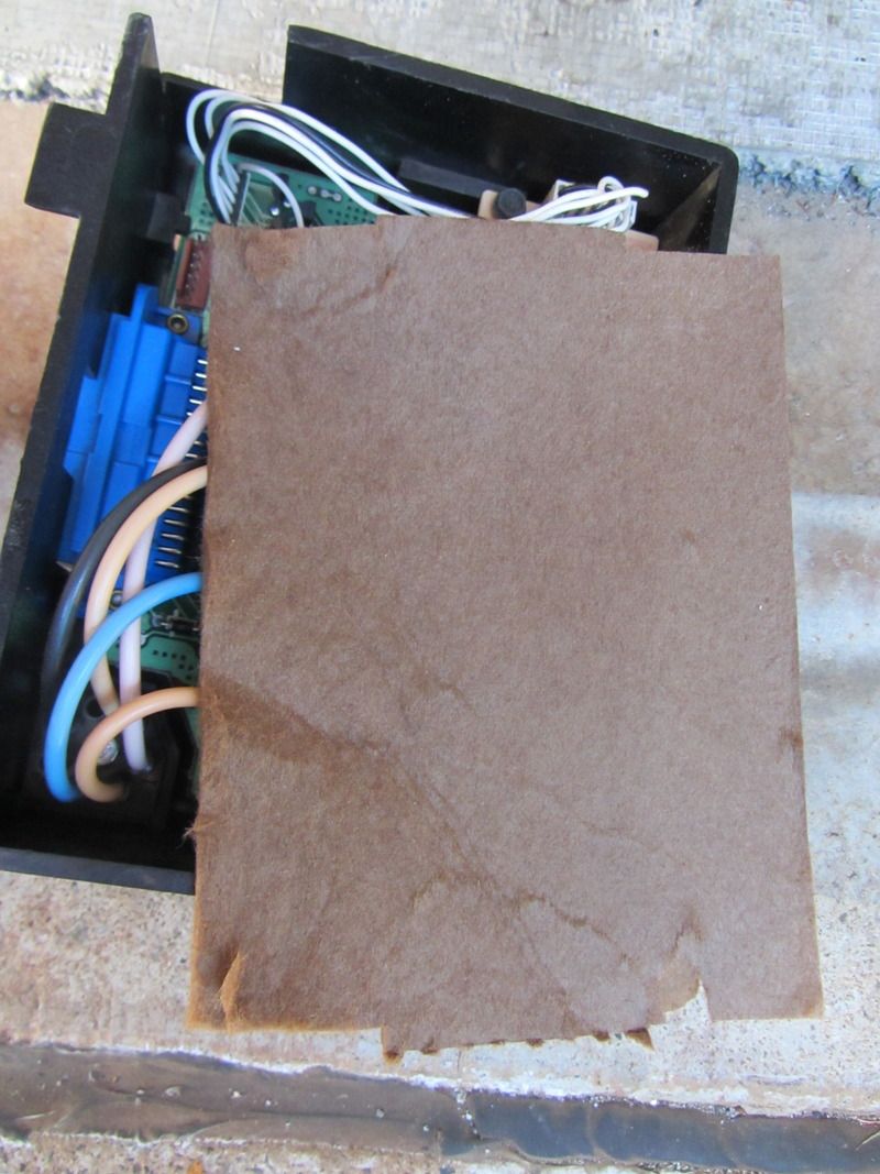
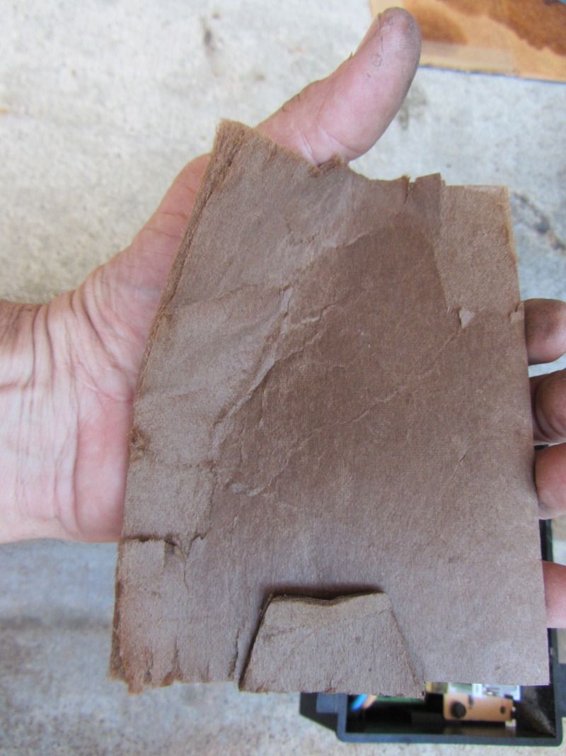
I did manage with a small right-angled pick to remove that push-nut from the vacuum block, but then, it was still not possible to unplug the vac block from the programmer box. There is nothing to gain purchase on to pull this apart, and I had to come up with a mechanism to pry under the vac block to finally work it loose. It NEVER needed that push-nut......you could pull the engine out using the force required to pull that delicate thing loose from the box. While I would like to show photos of the block, and the thing in position, it is not possible to bring light to bear on the assembly while holding it still and simultaneously trying to focus a camera up in there. What is reassuring though is that it will only go on one way since the block has a cut-out corner that matches the inset on the plastic box. Like I said, I'd rather use toilet paper made out of crushed Habeneros than do this again. Cliff mentioned he didn't bother taking a photo of the cardboard back of the box though, so I did that for him. It's more like a thick paper towel held on by electrical tape, which I removed. Here you go.
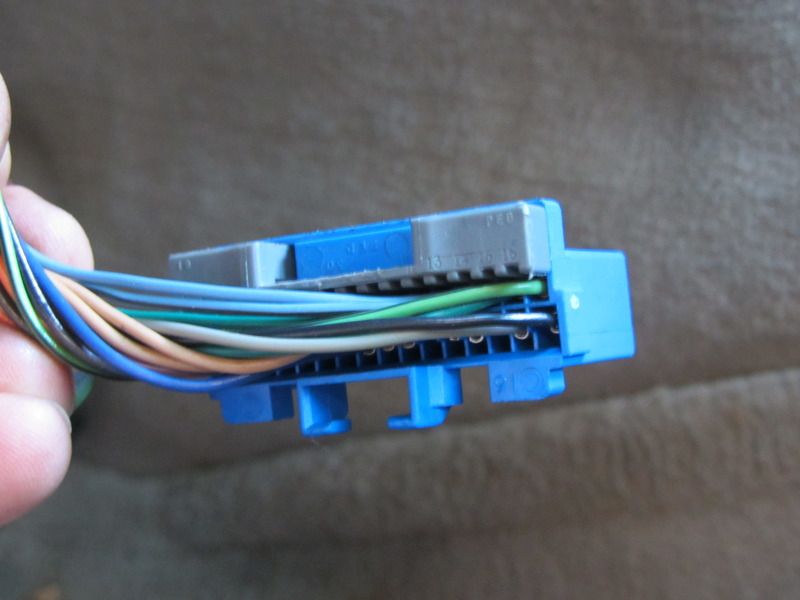
I would like to be able to shed some light on the retainer on the plug that goes into the box, but I did manage to feel what seemed to be a tab, and when I pressed down delicately and apprehensively on that, it crumbled and various pieces fell off. I could see the "comb" looking piece and the two tabs that hold it on, but I believe its only function is to retain the individual pins/wires into the connector and did not need removal. Again, the connector required considerable force to pull it free, even with the retainers obviously fractured like eggshells. Again, even with connector tabs obviously broken, you could pull the motor with the force required to pull them apart. Retainers? They don't need any stinking retainers. Somehow I pried it apart, and here is the carnage.
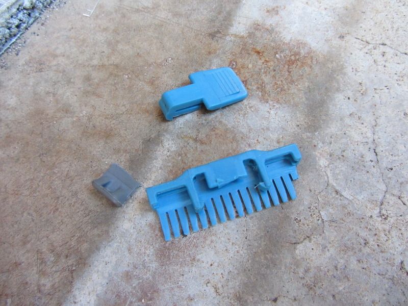
The connector is here, the gray tab matches that blue comb piece, and looks like it merely holds the pins in place on the 2nd row of wires in the connector. I will of course replace the blue comb thing so it will hold the pins in on row 1.
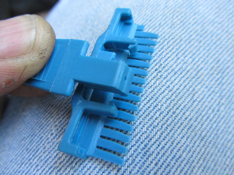
From the pieces shown in the carnage photo, the broken off blue tab belongs like this.
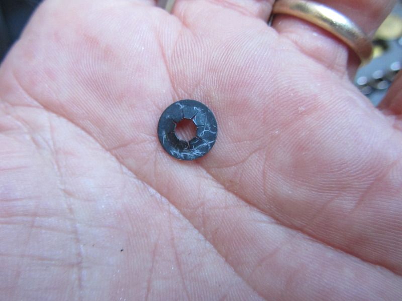
And of course the inaccessible push nut that holds in the vacuum block to the back side of the programmer box. Once I go toss it in the Volcano, I'll come up with my own retaining mechanism here, and of course it will be better than what their "engineers" came up with, but I really doubt it is needed. That connection is so tight with just pushing it together that you really have an epic struggle to separate the two components.
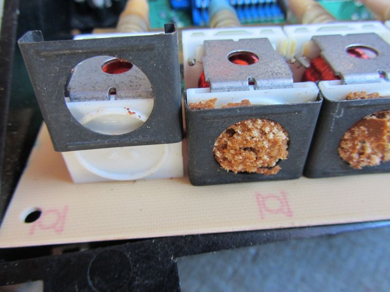
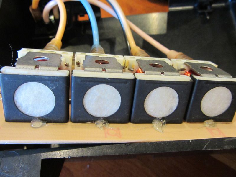
So what do I have now? Some questions of course. On my vacuum solenoids, what on earth is this crud?
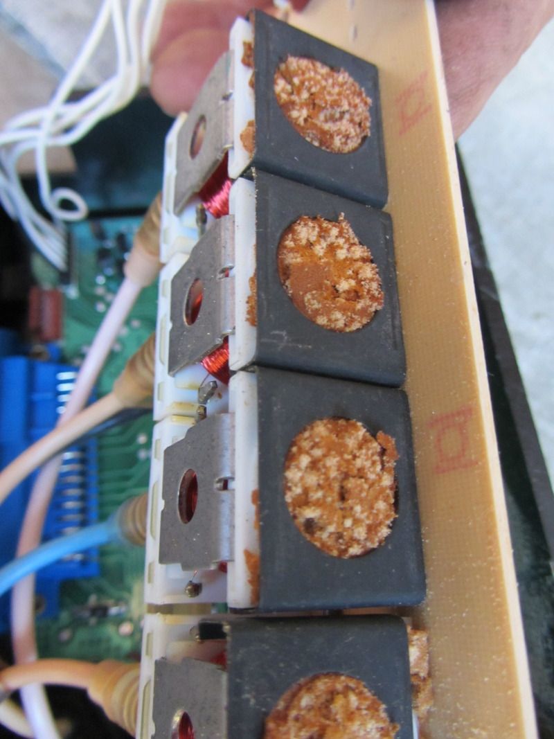
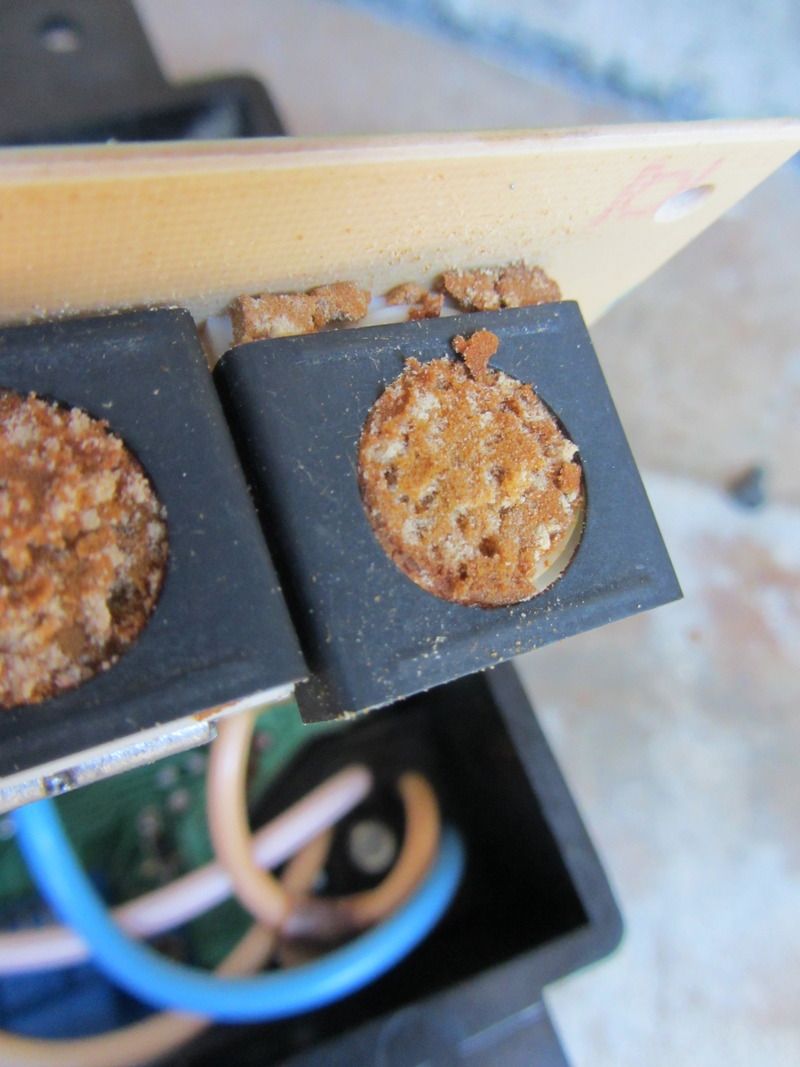
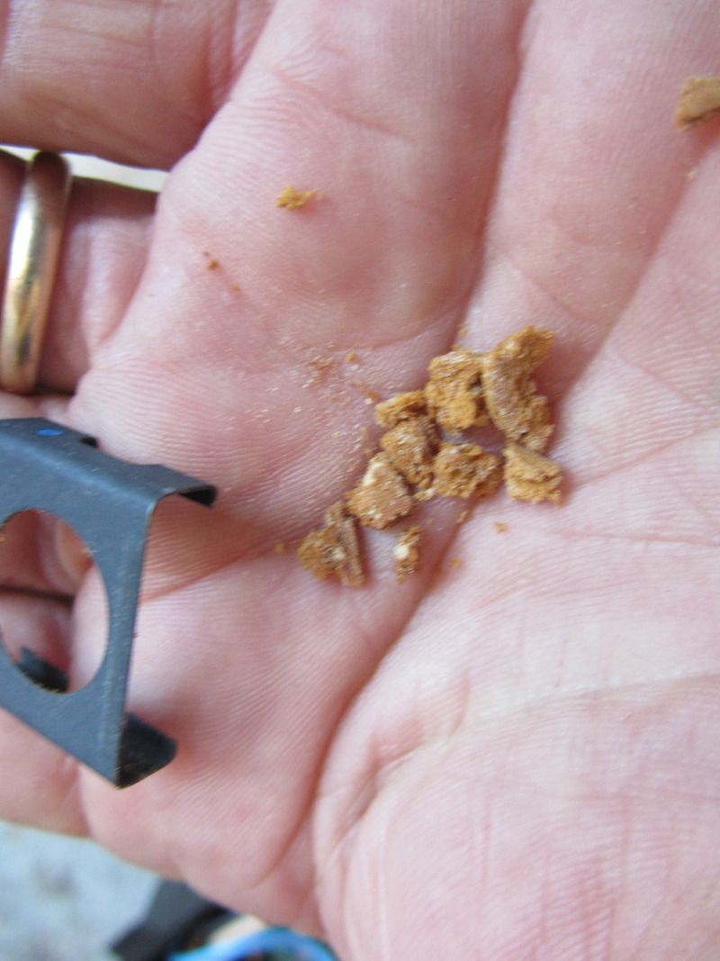
I have not seen this in all the other photos of this component I have seen. It appears to be some sort of deteriorated vacuum filter, or a cushioning spacer, but without it that black retaining clip just slips off. Is it possible that some of the deteriorated filter/whatever has been sucked into the vacuum solenoid or vacuum lines, rendering then non-functional? I'm not sure how to go about cleaning that out either if it has gotten inside.
I need to move to another post/entry so I don't hit the photo rev-limiter.
While I recognize that in other threads I have researched and reviewed, there has been mention of some difficulty and challenges in this task. I would rather experience multiple 10 gauge trans-perineal core biopsies of the prostate than have to do this task even the first time. Why didn't they just have a pigtail on the box, so that the connector was down low in the wiring harness? The wiring harness hangs easily into the footwell, so why not put the connector there??? The limiting factor in manipulating this instrument of the devil is not the wiring connector though, but the vacuum block. Could there really be any reason that this is mounted by an inaccessible push-nut rather than a threaded/extended dowel? The connectors here have far far greater strength than the delicate components they connect. I found that dropping down the steering column and pushing it further to the left made it a bit easier to remove the box, but barely above the impossible rating it should have. I believe all the negative commentary on this process has just been too delicately described.I did manage with a small right-angled pick to remove that push-nut from the vacuum block, but then, it was still not possible to unplug the vac block from the programmer box. There is nothing to gain purchase on to pull this apart, and I had to come up with a mechanism to pry under the vac block to finally work it loose. It NEVER needed that push-nut......you could pull the engine out using the force required to pull that delicate thing loose from the box. While I would like to show photos of the block, and the thing in position, it is not possible to bring light to bear on the assembly while holding it still and simultaneously trying to focus a camera up in there. What is reassuring though is that it will only go on one way since the block has a cut-out corner that matches the inset on the plastic box. Like I said, I'd rather use toilet paper made out of crushed Habeneros than do this again. Cliff mentioned he didn't bother taking a photo of the cardboard back of the box though, so I did that for him. It's more like a thick paper towel held on by electrical tape, which I removed. Here you go.


I would like to be able to shed some light on the retainer on the plug that goes into the box, but I did manage to feel what seemed to be a tab, and when I pressed down delicately and apprehensively on that, it crumbled and various pieces fell off. I could see the "comb" looking piece and the two tabs that hold it on, but I believe its only function is to retain the individual pins/wires into the connector and did not need removal. Again, the connector required considerable force to pull it free, even with the retainers obviously fractured like eggshells. Again, even with connector tabs obviously broken, you could pull the motor with the force required to pull them apart. Retainers? They don't need any stinking retainers. Somehow I pried it apart, and here is the carnage.

The connector is here, the gray tab matches that blue comb piece, and looks like it merely holds the pins in place on the 2nd row of wires in the connector. I will of course replace the blue comb thing so it will hold the pins in on row 1.


From the pieces shown in the carnage photo, the broken off blue tab belongs like this.

And of course the inaccessible push nut that holds in the vacuum block to the back side of the programmer box. Once I go toss it in the Volcano, I'll come up with my own retaining mechanism here, and of course it will be better than what their "engineers" came up with, but I really doubt it is needed. That connection is so tight with just pushing it together that you really have an epic struggle to separate the two components.

So what do I have now? Some questions of course. On my vacuum solenoids, what on earth is this crud?


I have not seen this in all the other photos of this component I have seen. It appears to be some sort of deteriorated vacuum filter, or a cushioning spacer, but without it that black retaining clip just slips off. Is it possible that some of the deteriorated filter/whatever has been sucked into the vacuum solenoid or vacuum lines, rendering then non-functional? I'm not sure how to go about cleaning that out either if it has gotten inside.


I need to move to another post/entry so I don't hit the photo rev-limiter.
Last edited by Opihi59; 06-15-2015 at 09:01 PM.
06-14-2015, 04:51 PM
#28
Bonehead
Thread Starter
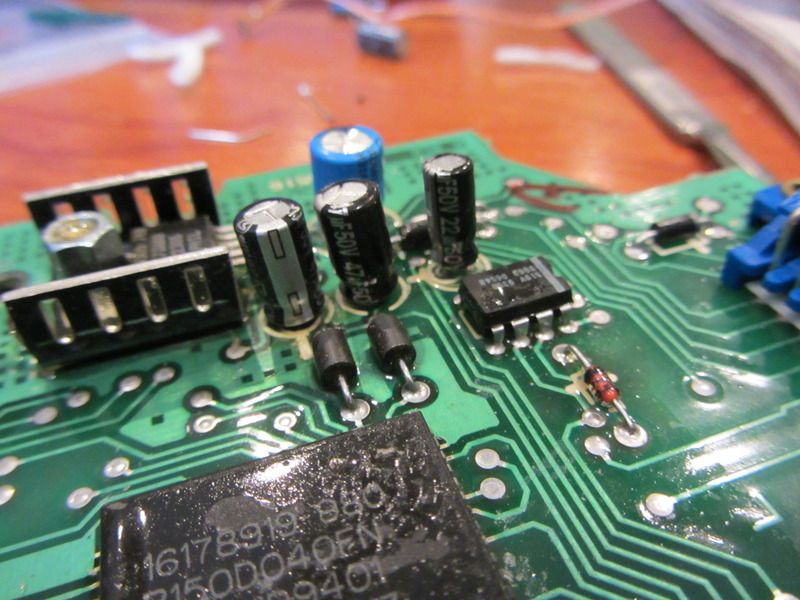
So some more photos, now of the board and the capacitors.
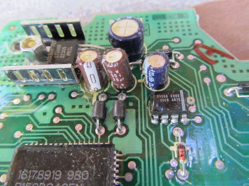
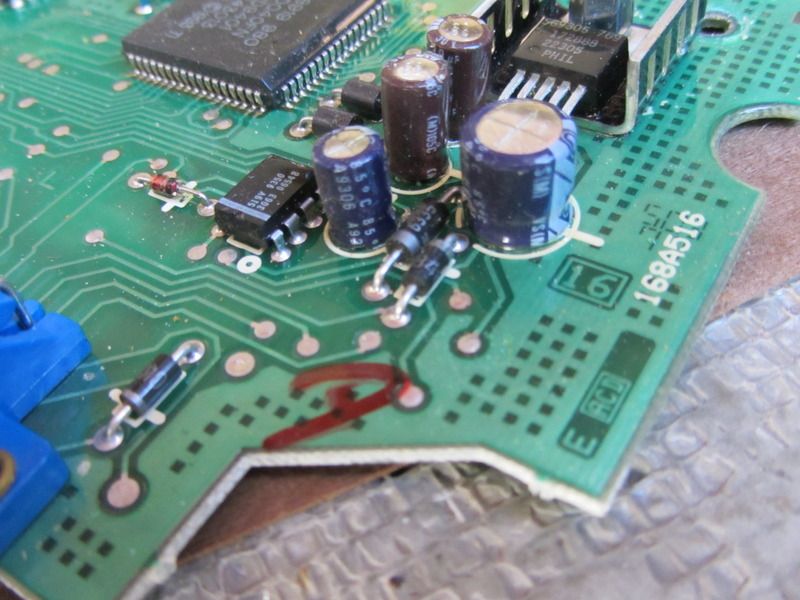
These are the capacitors incriminated in the index/seminal threads of the Programmer board failure. [Seminal: work, event, moment, or figure strongly influencing later developments--Thanks for your thread, pcolt94 and all your input throughout the forum on this Cliff Here is CLIFF's thread covering his 86 Programmer issues, some of the photos are very useful, even in the 94, and the troubleshooting is helpful] I am going to call up Radio Shack to see if they have them somewhere on the island. Leap of faith though, fully expecting the answer NO.
In looking over the board(s) with 3.5X jewelers loupes, I saw no evidence of poor connections, "cold" solder points, corrosion, obvious deterioration of board components, bulging/leaking capacitors, etc. I can only hope and guess that the capacitors are the problem faithfully based on the experience of others. Me? I'm totally unencumbered with knowledge or experience in this, so I do appreciate your input and sage guidance. Please throw me a bone, I did post up a ton of photos............


These are the capacitors incriminated in the index/seminal threads of the Programmer board failure. [Seminal: work, event, moment, or figure strongly influencing later developments--Thanks for your thread, pcolt94 and all your input throughout the forum on this Cliff
Here is CLIFF's thread covering his 86 Programmer issues, some of the photos are very useful, even in the 94, and the troubleshooting is helpful] I am going to call up Radio Shack to see if they have them somewhere on the island. Leap of faith though, fully expecting the answer NO.In looking over the board(s) with 3.5X jewelers loupes, I saw no evidence of poor connections, "cold" solder points, corrosion, obvious deterioration of board components, bulging/leaking capacitors, etc. I can only hope and guess that the capacitors are the problem faithfully based on the experience of others. Me? I'm totally unencumbered with knowledge or experience in this, so I do appreciate your input and sage guidance. Please throw me a bone, I did post up a ton of photos............
Last edited by Opihi59; 06-20-2015 at 01:07 AM. Reason: credit
06-15-2015, 12:21 PM
#29
Melting Slicks
You have been very busy!
The Deteriorated stuff over the top of the Vacuum Solenoids was probably an air filter at one time (foam) and just broke down over time. The Solenoids are "Probably" NC [normally closed] and require power to open (Just my guess) if this is true you can hook up a might Vac to each Solenoid, and test it for internal leakage..
In order to test the Capacitors, they have to be disconnected from the Board. This can be done with a Solder iron, a piece of Solder Wick, or a Solder Suction Gun. To test the individual Cap you will need a DVOM. The Caps have their Micro Farad Value listed on the outside of each Capacitor. It's the "uf" looking symbol.
http://en-us.fluke.com/training/trai...ultimeter.html
06-15-2015, 02:24 PM
#30
Bonehead
Thread Starter
You have been very busy!
The Deteriorated stuff over the top of the Vacuum Solenoids was probably an air filter at one time (foam) and just broke down over time. The Solenoids are "Probably" NC [normally closed] and require power to open (Just my guess) if this is true you can hook up a might Vac to each Solenoid, and test it for internal leakage..
In order to test the Capacitors, they have to be disconnected from the Board. This can be done with a Solder iron, a piece of Solder Wick, or a Solder Suction Gun. To test the individual Cap you will need a DVOM. The Caps have their Micro Farad Value listed on the outside of each Capacitor. It's the "uf" looking symbol.
http://en-us.fluke.com/training/trai...ultimeter.html
The Deteriorated stuff over the top of the Vacuum Solenoids was probably an air filter at one time (foam) and just broke down over time. The Solenoids are "Probably" NC [normally closed] and require power to open (Just my guess) if this is true you can hook up a might Vac to each Solenoid, and test it for internal leakage..
In order to test the Capacitors, they have to be disconnected from the Board. This can be done with a Solder iron, a piece of Solder Wick, or a Solder Suction Gun. To test the individual Cap you will need a DVOM. The Caps have their Micro Farad Value listed on the outside of each Capacitor. It's the "uf" looking symbol.
http://en-us.fluke.com/training/trai...ultimeter.html
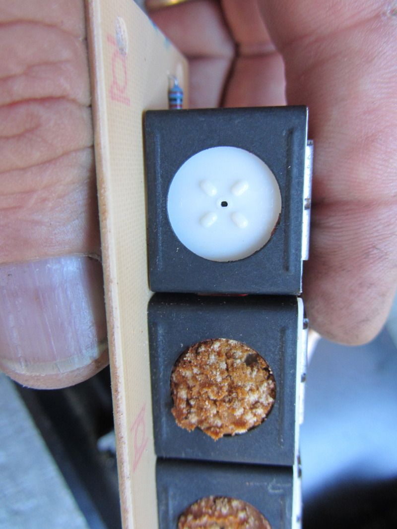
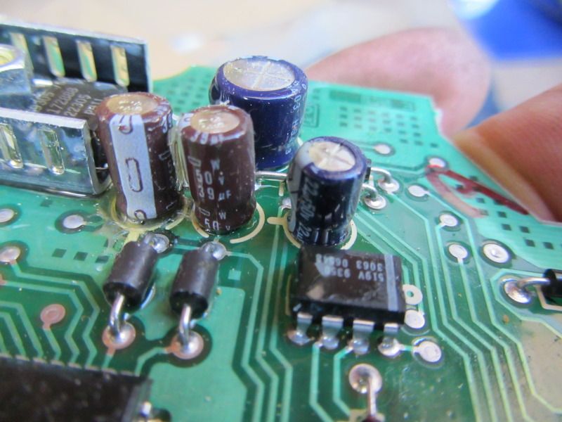
Thanks for suggestions. I did manage to find the 35 V 100 uf cap yesterday, and now that the "real" electronic store of the island is open, I'll go see if I can get the two 50 V 39 uf [or a pair of 47 uf if they dont' carry 39s] and one 50 V 22 uf. I did read that it wasn't possible to check capacitance without the caps removed, so if I'm going to remove them, I'm going to replace them with new. I did pretty much surmise that the deteriorated crud was at one time a filter, and will just put in a piece of thin loose weave felt. I found this photo, it shows intact filters here. Not my photo, but I don't know to whom to give credit.

I will let everyone know how the new capacitors work out of course, if I can get them in my grubby little hands and install successfully today.
I did get out there early enough before the sun came up enough to burn in on me, and enough darkness to test the Instrument cluster bulbs. I had just replaced them all and re-installed of course, and the right turn signal indicator bulb burned out while driving the other day....grrrr. I lost my race with the sun, but now the new bulb is in and the instrument cluster back in and other stuff around it, and the bulb works again. For now. Hope not to do that job again any time soon, but was half way there with the knee panels out and the steering column dangling. Brand new bulb that lasted all of a day. Grrrrrrrrr. At least seeing it was frosted/blown confirmed it was DOA rather than a loose connection somewhere in the circuit board of the Instrument cluster.

Last edited by Opihi59; 06-15-2015 at 06:54 PM.
06-15-2015, 02:25 PM
#31
Burning Brakes


It is hard to tell from your photos as they all look somewhat distorted. It appears that at least one of the 39uF caps is in need of replacement. I would also replace the foam filter inserts with new. Should be able to find it at any home hardware/repair store.
Just a side not with you compressor cycling. Have you had your system pressure checked since having it filled? Schrader valves are known to fail. Just quick insurance and piece of mind to have it checked.
Just a side not with you compressor cycling. Have you had your system pressure checked since having it filled? Schrader valves are known to fail. Just quick insurance and piece of mind to have it checked.
06-15-2015, 02:39 PM
#32
Burning Brakes
As far as your OAT is concerned, the FSM states
"After an OAT sensor has been changed or is open, the external temperature will read -50 F and Diagnostic Trouble Code (DTC) will be set until the vehicle has been driven over 25 MPH for 3 minutes."
"The OAT Display will not increase until the vehicle is driven over 25 MPH for 3 minutes."
"After an OAT sensor has been changed or is open, the external temperature will read -50 F and Diagnostic Trouble Code (DTC) will be set until the vehicle has been driven over 25 MPH for 3 minutes."
"The OAT Display will not increase until the vehicle is driven over 25 MPH for 3 minutes."
06-15-2015, 02:59 PM
#33
Melting Slicks
You might also check to see whether the electronics' store carries (Conformal coatings) in a small bottle.
https://en.wikipedia.org/wiki/Conformal_coating
https://en.wikipedia.org/wiki/Conformal_coating
06-15-2015, 06:38 PM
#34
Bonehead
Thread Starter
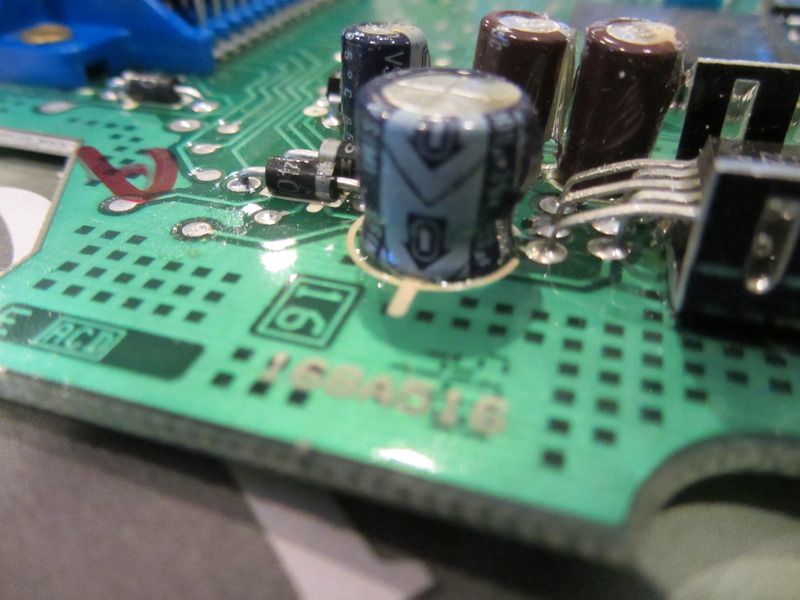
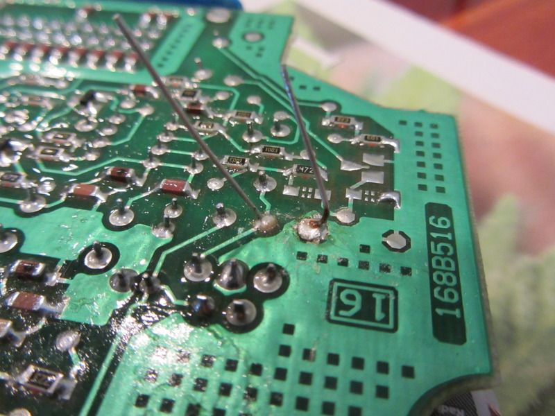
Okay, time to check back in and tell you it is working properly now. I replaced the 4 capacitors. It was challenging (for me) desoldering successfully and then sucking out the holes to have a patent lumen so I could feed in the new capacitors. Desoldering braid was not helpful, and I ended up having to pose my push-button solder sucker on one side of the board, while I heated the solder in the thru hole from the other, and then triggered the sucker. To remove the caps, I ended up "walking" them out by heating one leg while pulling on that side of the cap, then heating the other, etc until they came out. Soldering them back in was also a challenge to a circuit board neophyte such as my self. Number 3 son home from college breezed thru and commented that it resembled a monkey ***king a football. That was less than encouraging as I had already burned my hand (there goes half my love life.. ) when the cat decided to play with the tantalizingly dangling electrical cord to the soldering iron I had just set down, so when he pulled it off the table, I grabbed it. Duh. Eventually managed to desolder all the caps, open the holes, and solder in new caps. I couldn't find 39uf so went with 47uf and retained the same voltage level on all the caps. While Cliff's 100uf cap was 50 V matching all the others, on mine it was a 35V so I stuck with that rating. I found I could not test the old ones because apparently my tester does not measure capacitance. Suffice it to say that at least one of them had to be shot, as despite my clumsy work and goobered up soldering bubbles, it works now. If I come up with a tester, I will interrogate them and post in the results. These are all "polarized" caps, so it is important to put the negative leg in the correct hole. This is marked by a stripe on the can, and also the neg leg is the shorter of the two wires poking out the bottom of the can. I also noticed that on the circuit board there is a circle that shows where the capacitor goes, with a little "tab" painted like a small handle on the circle that shows the negative side. Very helpful, can see here in first photo.
All in--
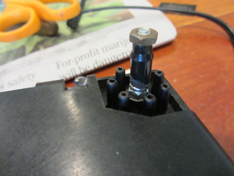
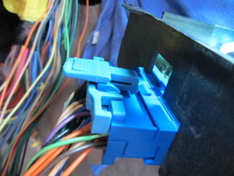
So just a few things I did, or want to document to help others confronted with this daunting task. For securing the vacuum block back into the programmer, I cut the "single" end off of the old vacuum check valve I replaced earlier in the thread and used it as a spacer sleeve on the threaded stud the push-nut was previously on. Then screwed a small nut (#8 X 32 tpi) on top of that. When I reinstalled the box, this is how I held the vac block back into the box, but I really don't think that is necessary. I did it nonetheless; here's how it looks. Final working length of this plastic spacer sleeve when installed is just a smidge over 5/16". It works.
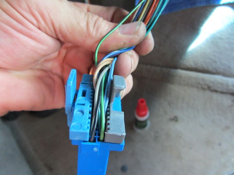
I reassembled the Programmer connector with a dab of super glue to show you how it should look if it isn't broken, which should shed some light on how to release the connector since you cannot see this when you are trying to disconnect it up under the dash. You can see that I reinstalled the Blue comb that holds in a row of connectors that I had removed earlier in the thread. The two combs do nothing to hold the connector to the Programmer box
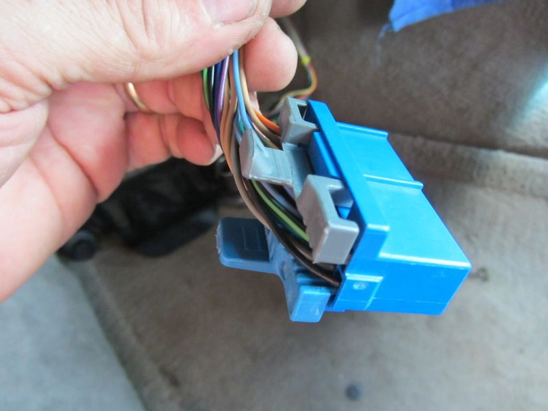
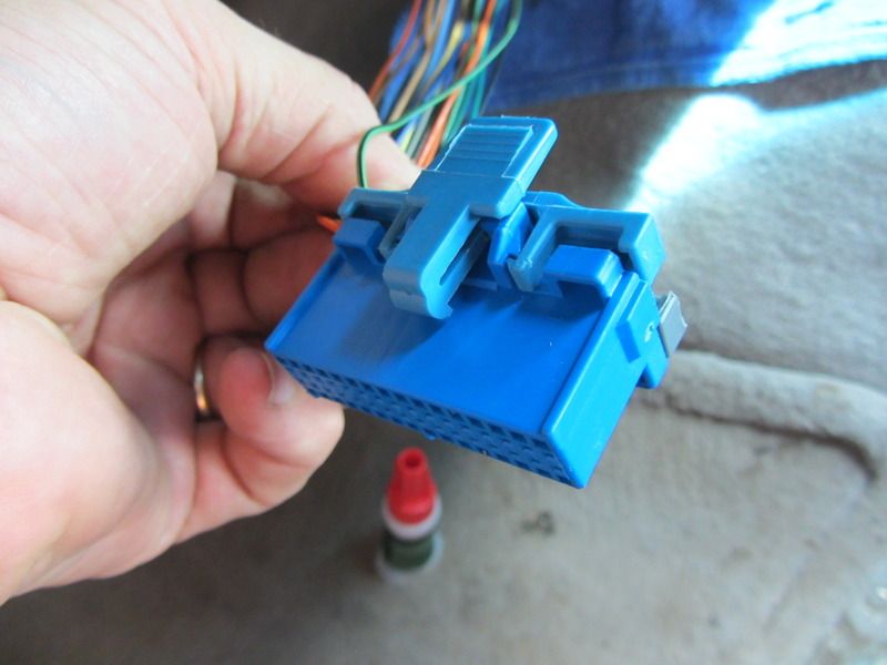
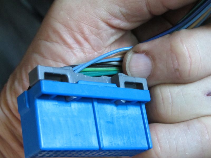
Here are 2 poser shots of how the retaining clip functions on this connector. Just disengaged, and engaged. The Blue tab is the key, mine snapped like an eggshell when I pressed it down at the start of this game.
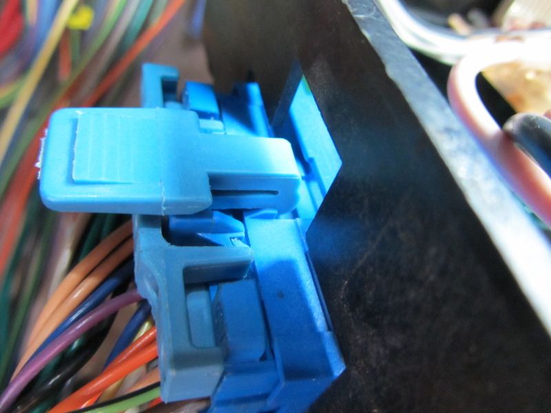
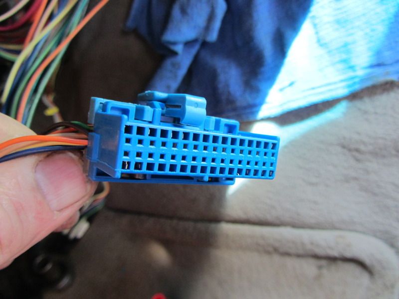
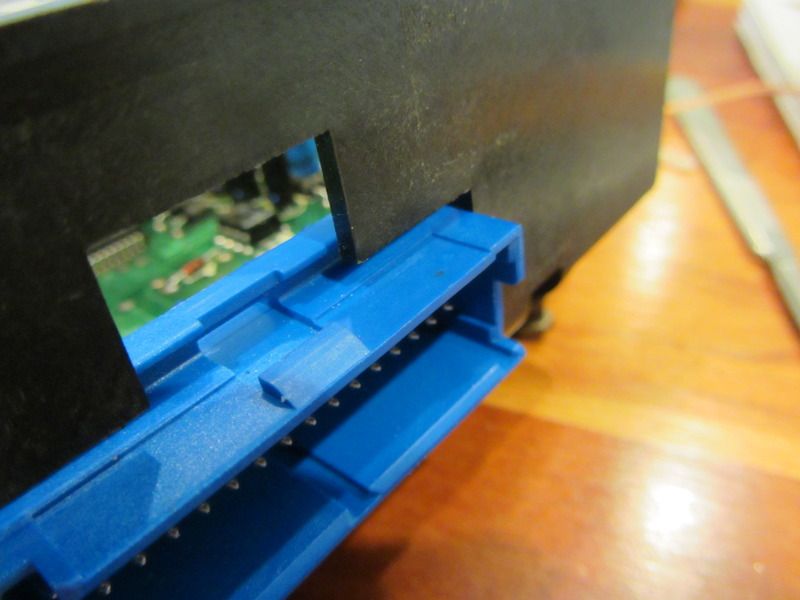
Somewhat diabolically, the depress tab is on the side which is up against the firewall when the programmer box is installed. Even depressed properly, or broken off completely, it is still tough to pull the connector from the box. I don't think mine is going to pull itself loose. The connector can only go back in one way. In the first photo of the connector a few photos up (6 photos up...) you will see a linear ridge in the male end. The female side on the Programmer has a matching trench that this mates up with. Flip it 180* and it will not go into the Programmer box. Here is a shot of the female side on the Programmer box.
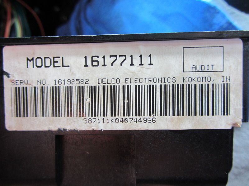
Here is the part number as shown on the ID label on the side of my box. I did not bother to put replacement piece of cardboard back on it.
On to another entry so as not to trigger the photo rev-limiter.
) when the cat decided to play with the tantalizingly dangling electrical cord to the soldering iron I had just set down, so when he pulled it off the table, I grabbed it. Duh. Eventually managed to desolder all the caps, open the holes, and solder in new caps. I couldn't find 39uf so went with 47uf and retained the same voltage level on all the caps. While Cliff's 100uf cap was 50 V matching all the others, on mine it was a 35V so I stuck with that rating. I found I could not test the old ones because apparently my tester does not measure capacitance. Suffice it to say that at least one of them had to be shot, as despite my clumsy work and goobered up soldering bubbles, it works now. If I come up with a tester, I will interrogate them and post in the results. These are all "polarized" caps, so it is important to put the negative leg in the correct hole. This is marked by a stripe on the can, and also the neg leg is the shorter of the two wires poking out the bottom of the can. I also noticed that on the circuit board there is a circle that shows where the capacitor goes, with a little "tab" painted like a small handle on the circle that shows the negative side. Very helpful, can see here in first photo.

All in--

So just a few things I did, or want to document to help others confronted with this daunting task. For securing the vacuum block back into the programmer, I cut the "single" end off of the old vacuum check valve I replaced earlier in the thread and used it as a spacer sleeve on the threaded stud the push-nut was previously on. Then screwed a small nut (#8 X 32 tpi) on top of that. When I reinstalled the box, this is how I held the vac block back into the box, but I really don't think that is necessary. I did it nonetheless; here's how it looks. Final working length of this plastic spacer sleeve when installed is just a smidge over 5/16". It works.

I reassembled the Programmer connector with a dab of super glue to show you how it should look if it isn't broken, which should shed some light on how to release the connector since you cannot see this when you are trying to disconnect it up under the dash. You can see that I reinstalled the Blue comb that holds in a row of connectors that I had removed earlier in the thread. The two combs do nothing to hold the connector to the Programmer box


Here are 2 poser shots of how the retaining clip functions on this connector. Just disengaged, and engaged. The Blue tab is the key, mine snapped like an eggshell when I pressed it down at the start of this game.


Somewhat diabolically, the depress tab is on the side which is up against the firewall when the programmer box is installed. Even depressed properly, or broken off completely, it is still tough to pull the connector from the box. I don't think mine is going to pull itself loose. The connector can only go back in one way. In the first photo of the connector a few photos up (6 photos up...) you will see a linear ridge in the male end. The female side on the Programmer has a matching trench that this mates up with. Flip it 180* and it will not go into the Programmer box. Here is a shot of the female side on the Programmer box.

Here is the part number as shown on the ID label on the side of my box. I did not bother to put replacement piece of cardboard back on it.

On to another entry so as not to trigger the photo rev-limiter.
Last edited by Opihi59; 06-15-2015 at 09:10 PM. Reason: Always clarifying
06-15-2015, 06:50 PM
#35
Bonehead
Thread Starter
For replacing the filters on the vacuum solenoids, I had some felt laying around. It seems to be a bit thinner than the stock foam filter would have been but it's what I had available.
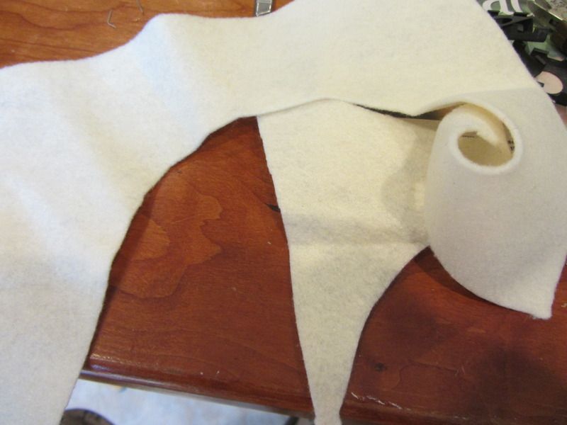
To make sure those metal "filter retainer clips" stayed in place with a thinner filter, I put little hot glue boogers on them against the board. I do not have a way to test the vacuum solenoids, so re-installed and tested. It seems they all work as the control head now functions with every button, and it seems to be closing the various doors when I cycle thru the function buttons on the head unit. I did notice that when I put it to the "blow on the feet" position, I still had a little whiff of air coming out the defroster vent. I don't think that's an issue, it just does not get cold here on the Island. The little trimmings off of the edges of the squares of felt I made proved irresistible to the cats, one of them ate one and then I heard him yakking it back up along with kitty breakfast and hairball on the limited edition Indich Wool area rug. Gotta love the cats.
The OAT sensor finally reads and displays on the head unit once again, which also shows the HVAC Temp setting when I cycle it. The compressor does not cycle on and off now either. Apparently without guidance from the Programmer, it didn't know whether to S**t or go blind, so it defaulted to on/off/on/off, etc.
Thanks to help from the forum, I've got it working properly again. While I did have a degree of skepticism on whether or not this would fix the problem, it ended up being the issue all along.
Last edited by Opihi59; 06-15-2015 at 09:14 PM.
06-15-2015, 06:50 PM
#36
Burning Brakes
I promise not to critique your soldering job as it sounds like you had your fair share already.
Excellent job with the repairs. What is next on the repair list?
Excellent job with the repairs. What is next on the repair list?
06-15-2015, 06:59 PM
#37
Bonehead
Thread Starter
Corvette repairs cut into my drinking time.
06-15-2015, 07:17 PM
#39
Bonehead
Thread Starter
