When you click on links to various merchants on this site and make a purchase, this can result in this site earning a commission. Affiliate programs and affiliations include, but are not limited to, the eBay Partner Network.
hi, first i would like to start by thanking you all for your help. this forum has provided alot of info for me. My car is an 87 corvette coupe.
I recently took on a big job, i changed the radiator to a double row dewitt, a flowkooler water pump, a spal fan, a new timing set and changed the oil pan/timing gaskets.
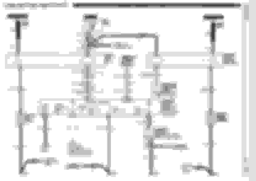
The previous owner put in a switch for the radiator fan. i would like to put the wiring back to stock, dont want the switch anymore. How do i do this? i have the service manual. i attached the wiring diagram page but i cant understand it. is this a simple job? what do i have to do? when i look at it i have the wires that go from the radiator to an in line fuse, and then the coolant sensors lines go to a fuse also, and then there are 3 wires that go to the inside of my car. there is a wire that is cut, it is black i believe. please help if you can. thanks.
You need to first determine how the car would have been built originally. Not all had the HD Cooling Fan option so that would change somewhat how to interpret the wiring schematic. The SPID label on your car would be on the center console door, post a snapshot of that OR did your car actually have a fan in front of the radiator/condenser module as well as one on the back-side of the radiator?
Is your SPAL a 2 fan or single fan unit?
I'd think it NOT difficult but I'd think you need to inventory what's still actually bolted to and wired on the car.
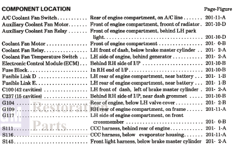
The page after your wiring diagram would have a "components location" section with references to a 201-XX-x which would be snapshots of assumed component locations. You could check that page following the wiring diagram and the 8A-201 section of the FSM and do the inventory.
XX = page x = image on page
This is what I'd expect on the following page in the FSM
hi guys, so my radiator fan in between the radiator and the engine is on all the time also, not sure why. can anyone help me with this?
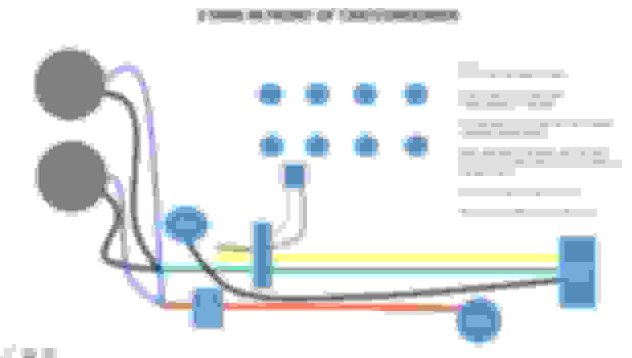
below is a picture of how my car is set up. it is an 87 corvette coupe. the previous owner put a switch in the car for the 2 fans in front of the condenser and changed the wiring for the fan between the engine and radiator.
I am willing to keep the switch but i would like to bring it back to stock. can anyone tell me how to do this? or how to keep the radiator from not being on all the time?
Last edited by mrm4155; 08-24-2016 at 10:47 PM.
Reason: typo
2020 Corvette of the Year Finalist (appearance mods)
C4 of Year Winner (appearance mods) 2019
Originally Posted by mrm4155
How do i do this? i have the service manual. i attached the wiring diagram page but i cant understand it. is this a simple job?
Let's start with your understanding first. To me, it's a fairly simple job except for the potential headache in tracking down where your factory wiring was cut. It COULD be hidden fairly well. Mostly, you just want to find the green/white wire going to your ECM.
From here, I want to explain the diagram.
What you are looking at is the computer (ECM) in the middle. You can clearly see the fan motors on each side and the relays that "trigger" them.
Relays are used where switching can't handle the amperage (amount) of electricity pulled through the wires. In this case, the computer grounds the circuit and turns on the fan. But, the computer can't handle the amperage being directly in a fan circuit.
Relays used here have a low/trigger side. They also has a high power side. The high power side is what's hooked to the fans. The low-power side is an internal magnet that "yanks" the high power side on.
The main fan is triggered by the computer (ECM) seeing a high enough coolant temperature to close it's own, internal relay. That causes the main fan's relay to energize, then "yank" it's high-power switch closed. Power flows from the battery (fusible link) to the fan, then to ground.
The aux fan is ONLY triggered by the switch in the head between cylinders 1 & 3. When the engine get's hot enough, that switch in the head "closes". In the schematic, you'll see an arrow coming out of the bottom of the "Coolant fan temperature switch". That's a ground. The ground is your engine. And, the coolant switch (for the aux fan) is what triggers the relay to turn on THAT fan.
If you buy two relays (which are the same), I think they come with mounting brackets BUT they won't have the corresponding plug from the wiring harness. The easiest way to "create" those is to get them off a salvage/donor car. Hopefully, you can find a person/yard that will sell them WITH pigtails of the original wire still attached.
I think you want both relays AND both plugs that go INTO the relays. Once you get these in hand, it's a matter of telling you which wires match up to the "pigtails" on the plugs. From the schematic, the colors SHOULD be fairly obvious....especially if you know the basics of electricity.
To loop back where I started, the other challenge will be finding the green/white wire. THATS the one that will reconnect you to the computer -- to control (ground) the main fan. The rest of the wires can be rerun without having to find their originals under your hood.
If YOU were the one that did much of this conversion, then you might just know where everything is.
Thanks a lot. I understand now. I didn't know the middle was the ecm. Now I will have to disect the wiring to see what is still there and what the previous owner took out. I don't think the previous owner changed to much. I'm. Pretty sure the original relays are still there.
I know I have the main fan rely still. I will see if the previous owner took out the aux fan relay. I want to also check to see if he took out the fuse in the fuse block since he has an in line fuse there. Hopefully the dk blue wires to the fuse are still there. We will see. I think I got it now. Again thanks alot.
2020 Corvette of the Year Finalist (appearance mods)
C4 of Year Winner (appearance mods) 2019
I'm glad it's making more sense. The OTHER complicated part (which I didn't cover) comes down to the power requirements for your fans. You have a LOT of fans. You'll need to determine their electrical load on the charging system...and possibly if/how much they might be drawing down at idle.
It has been pointed out many times that there is a limit to what the alternator can provide at idle. You may have a 105-amp alternator...but at idle, it outputs about 1/3 of that. (Don't quote me on that figure). My point is your fans may be running slower than their potential -- at idle -- in addition to stereo, headlights, etc.... Have you observed anything to believe that might be happening?
I actually need to upgrade my fan(s) as well. I have a "better-than-stock" radiator that introduces it's own "problem" by restricting air flow through it's multiple rows. (At least that's what I've decided after digesting information on the subject.) In short, thicker radiators often restrict air flow -- which is why so many people end up needing "more fan" to pull air through them. But there is no "formula" for deciding how MUCH fan you'll need. Nor, is there a formula for deciding if/how much more power you'll need to drive the fan(s). I do think it takes "a lot of fan" to duplicate the air flow BELOW 35mph where your fans are programmed to run by the factory. Maybe that's what the PO of your car was after.
The electrical consideration can be a PITA to consider...especially if you try to add the fans w/o wanting to use external fuses and/or upgrade the alternator. (They do make 200-amp alternators if you need that upgrade.)
I don't have time to reread what I wrote right now, but I covered/questioned lots of the power considerations in a previous thread I ran a couple of years ago. You can find it here: https://www.corvetteforum.com/forums...?highlight=fan
If you read through it, you might find additional details to consider when deciding how to resupply power to your relays/fans...especially with regard to fusible links and/or external fusing. (If you don't know, fusible links are short pieces of smaller gauge wire that act pretty much like slo-blow fuses. When power overloads, they melt. They are replaceable....just like a fuse. I'm not an expert on their construction but their gauge (and length?) determine their "fuse rating".)
From what you wrote in your last post above, I want to make sure you realize the amperage in the dark blue wires -- that trigger the low side of the fan relays -- don't draw much power from a circuit. I'm saying power for THAT branch in the fan circuit can be acquired from several "hot leads" in the engine bay.
So I got up this morning and looked at the main fan wiring. The previous owner put in an in line fuse, and that's it, probably since the fan that was in there was not stock. I bought a spal fan to replace that. Once I wired it up and changed the relay everything is in working order for the main fan. I didn't check to see if it turns on at 236 but it did turn on and off with the ac and it didn't run constantly like before.
On to the Auxiliary fan which is hooked up to the switch. Summit has a wiring kit that I'm thinking about using to just rewire the whole fan, which I'm going to buy new/upgrade and have it turn on/off at 200/185. I have a 180 thermostat already and dewitt double row radiator so it should keep nice and cool with that set up.
2020 Corvette of the Year Finalist (appearance mods)
C4 of Year Winner (appearance mods) 2019
All you need to do is install a relay for the aux fan. Those can be purchased for about $5 [versus the $85 for the kit]. That's assuming you don't totally HATE the wiring already in place for the aux fan.
The relay could be spiced into most any power supply (hot lead) to trigger the relay. It's ground would be your coolant fan switch in the block -- which, when closed, creates a circuit to energize the relay.
You already have the high-power side of your aux circuit in place -- as it's already running those fans. The high-power side of a new relay would be spliced into your red wire. The green wire should run straight to ground.
Make sense?
BTW: I'm not sure it makes any sense to trigger the aux fan at a temp lower than your main fan operates. I would think most tech guys would suggest pusher fans aren't terribly efficient. It's your new SPAL that's going to carry the load. Shrouded fans do a MUCH BETTER job getting air through your radiator.
If you DO want to trigger the aux fans at 200(ish), MAM sells a coolant temp switch for $15 + s/h. In fact, I just bought one that I might resell for $15 shipped. In my case, I'd prefer my aux fan come on 10-20 degrees higher. The downside is the MAM coolant switch MAY never shut off since it's unclear if there's actual "room" between it's shut-off point and even a 180 thermostat! I used to think not. Now, I'm wondering if it would in cars that are still stock. (There are a couple of current threads discussing an apparent discrepancy in head versus stat temps...which MAY only be true for those of us running non-restrictive intake gaskets.)
If your main fan is working now I wouldn't mess with it for the auxiliary fan.I have an 87 vette and bought a kit from Eclers Corvette to turn the main fan on at lower temp.I put the temp sensor in the head and wired the lead to the factory fan relay on my fender skirt.I followed the instructions to the letter.It play havoc with the rest of my sensors.I pulled it off and put it back stock.
2020 Corvette of the Year Finalist (appearance mods)
C4 of Year Winner (appearance mods) 2019
Originally Posted by steven mack
If your main fan is working now I wouldn't mess with it for the auxiliary fan.I have an 87 vette and bought a kit from Eclers Corvette to turn the main fan on at lower temp.I put the temp sensor in the head and wired the lead to the factory fan relay on my fender skirt.I followed the instructions to the letter.It play havoc with the rest of my sensors.I pulled it off and put it back stock.
Hey Steven...I'll be the first to admit Ecklers isn't anywhere near the top of my Corvette suppliers list but it sounds like you had problems waaay before trying their switch.... https://www.corvetteforum.com/forums...post1580175319
Hi Greggpenn I haven't changed my Avatar pic yet but I have a different Vette I bought this year.The fan worked just fine and like it is supposed to before the new switch was tried.I just finished putting in a 400 small block in.I hadn't driven the Vette Because of the wierd things it was doing.My wife says just drive it and see what happens.Well I did and the fan worked perfectly and all the other stuff stopped happening.like service engine light coming on and 5 different solenoids coming on at startup along with the fan.Things do change in 4 years .I went from a Vette to a third Gen Camaro and back in that Time
Last edited by steven mack; 08-26-2016 at 05:35 PM.
Reason: add info
2020 Corvette of the Year Finalist (appearance mods)
C4 of Year Winner (appearance mods) 2019
Originally Posted by steven mack
Well...the fan worked perfectly and all the other stuff stopped happening.like service engine light coming on and 5 different solenoids coming on at startup along with the fan.Things do change in 4 years .
But not the fundementals of electricity. Our universe may have an extra planet, but electricity still works the same!
I invite you to scan and post the instructions provided by Ecklers. There's no way an aux fan kit should/could have affected unrelated sensors!
Just cause you say so don't make the corn grow.Before I did the switch I took the instructions and the Chiltons wiring diagram over to my friends house who has been a mechanic for 45 years and owns a machine shop.I asked him if i was understanding the instructions properly.He looked them over and said I was.I know it shouldn't have caused the problems that it did.But it sure Damn well did.There is only one wire that is to be tapped into on the relay .That is the green wire with the white stripe .Then you put the sensor into the cylinder head and plug the wire into it.It's not rocket science.
Last edited by steven mack; 08-26-2016 at 07:33 PM.
Reason: addinfo
2020 Corvette of the Year Finalist (appearance mods)
C4 of Year Winner (appearance mods) 2019
Originally Posted by steven mack
Just cause you say so don't make the corn grow.Before I did the switch I took the instructions and the Chiltons wiring diagram over to my friends house who has been a mechanic for 45 years and owns a machine shop.I asked him if i was understanding the instructions properly.He looked them over and said I was.I know it shouldn't have caused the problems that it did.But it sure Damn well did.There is only one wire that is to be tapped into on the relay .That is the green wire with the white stripe .Then you put the sensor into the cylinder head and plug the wire into it.It's not rocket science.
I agree with your first statement.
Sometimes when you think you've figured something out, a new explanation may reveal what's really going on. If you're not willing to discern what [about the kit] caused an issue, that's perfectly alright. Advising people not to take action in their own situation -- because you had a problem (that's apparently not specifically resolved) doesn't seem like the best advice.
Aren't you the slightest bit curious what about that mod caused the behavior you saw?
Edit: The most logical thing (I can think of) is to consider a "system-wide" voltage drop caused multiple sensors to perform erratically. As mentioned earlier in this thread, alternators don't do well when loaded with lots of accessories -- at idle. The more things you turn on, the more likely you might be to have erratic behavior.
Also, I don't mean to come across as argumentative. Some of my older threads sometimes came off that way. I like to debate unresolved issues in hopes of figuring things out. That's the biggest advantage of a forum...to share information and discover the "who, what, where, when" about topics.
GreggPenn I have always enjoyed your posts.They are always informative and I learned a lot from them.I have a brand new alternator on the Vette.I sure as heck do want to know what caused the problem.I have an 87 the original poster has an 87.I don't want to give anyone bad advice.Your explanation to him was logical and well thought out.But what happened to me made absolutely no electrical sense .I figured if his fan was working properly now don't mess with it.And we don't have a new planet in our solar system it's been there all along according to the latest fly by pictures.It's called Pluto.their reasoning That Pluto couldn't be a planet was that it was in the Kyper belt of asteroids.Well this supposed new giant planet would have to be in the same region.Ergo it couldn't be a planet.
2020 Corvette of the Year Finalist (appearance mods)
C4 of Year Winner (appearance mods) 2019
Originally Posted by steven mack
GreggPenn I have always enjoyed your posts.They are always informative and I learned a lot from them.I have a brand new alternator on the Vette.I sure as heck do want to know what caused the problem.I have an 87 the original poster has an 87.I don't want to give anyone bad advice.Your explanation to him was logical and well thought out.But what happened to me made absolutely no electrical sense .I figured if his fan was working properly now don't mess with it.And we don't have a new planet in our solar system it's been there all along according to the latest fly by pictures.It's called Pluto.their reasoning That Pluto couldn't be a planet was that it was in the Kyper belt of asteroids.Well this supposed new giant planet would have to be in the same region.Ergo it couldn't be a planet.
Thanks Steven. Kudos to many of yours too.
As for fans, it's nice to strive for...and finally have a modified setup that you can "forget about" and count on to work "as good as factory". I'm still (slowly) chasing an issue/two from my 2010 build. Cooling (at idle) is one of them. As such, it's nice to talk about what others have done...why...and how it turned out.
I missed that that article on the other planet thanks for sharing it with me.I feel your pain about chasing down an electrical problem.As for your advice to the OP The green wire with yellow tracer is indeed one of the main wires to look for.And I also liked the posts you found about my fan problems in 2012.I cannot believe I am back their again.Thanks,Steve
If your main fan is working now I wouldn't mess with it for the auxiliary fan.I have an 87 vette and bought a kit from Eclers Corvette to turn the main fan on at lower temp.I put the temp sensor in the head and wired the lead to the factory fan relay on my fender skirt.I followed the instructions to the letter.It play havoc with the rest of my sensors.I pulled it off and put it back stock.
If I'm not mistaken, that kit from Ecklers is not a sending unit (thermistor- variable temperature dependent resistor) which the ECM needs to function properly, but only a on/off switch driven by temperature. I just purchased that kit intending on lowering my op temp but when I read the instructions that came with the kit, it was clearly intended to replace the 1987 AUX fan switch in the drivers side head... which does not run the main fan. My 87 never had an AUX fan from the factory, so the head was not drilled and there was no such factory switch in the drivers side head. Their catalog does not make this clear. It's in the instructions that come with the kit. I sent it back. FYI.
Well I had the switch setting around for about 4 years So I certainly could be mistaken about where I got it from.It Had GMP and lingenfelter on the package.It was 200 degrees on 180 off.The instuctions didn't say anything about it being an AUX.switch.But it very well could have been.I only have one fan on my Vette.But thanks for the heads up.
Last edited by steven mack; 08-27-2016 at 06:56 PM.
Reason: spelling
 08-22-2016, 06:06 PM