When you click on links to various merchants on this site and make a purchase, this can result in this site earning a commission. Affiliate programs and affiliations include, but are not limited to, the eBay Partner Network.
Additional Calculations Links are provided herein. These Links provide for quick determinations of:
a. 1/4 Mile ET
b. HP
c. MPH
d. RPM
e. Speed
f. Gear Ratios
g. Wheel Offset.
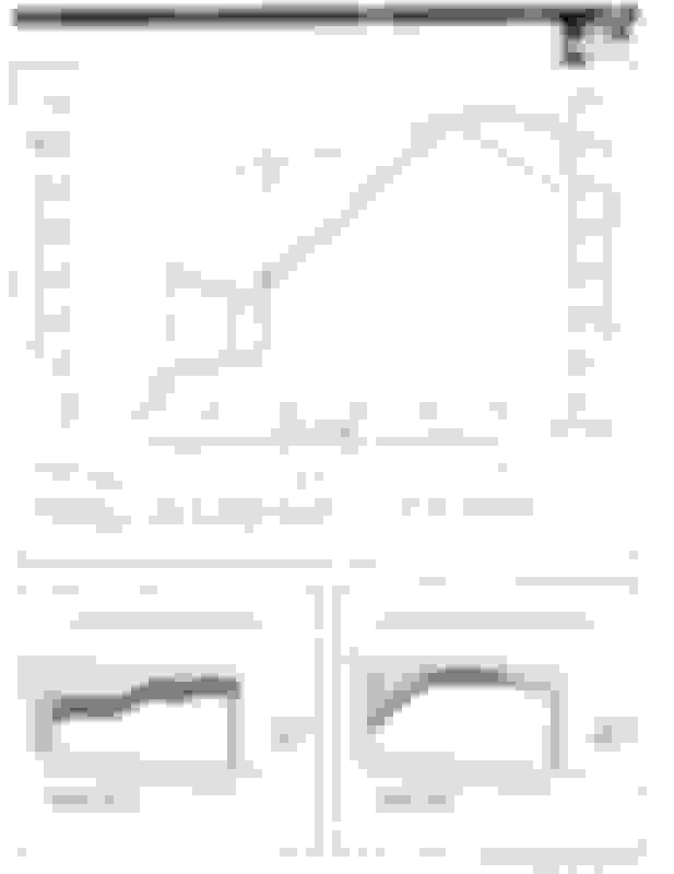
Tech Info - LT5 Horsepower and Torque Calculations
Tech Info - LT5 Horsepower and Torque Calculations
One horsepower is defined as Omega T or rotation speed (radians per second) multiplied by torque (foot-pounds)
One horsepower is defined as 550 foot-pounds per second (33,000 foot-pounds per minute). Engine speed is revolutions per minute (rpm). The units of torque are foot-pounds.
A radian of a circle is a ratio of the length of an arc divided by the length of a radius, so the units of length cancel out and you're left with a dimensionless measure called a radian.
One revolution is 360 degrees of a circle. The circumference of a circle is 2 x pi x radius (there are 2pi radians in a revolution where pi is 3.14 which is the ratio of circumference of circle to radius). To convert revolutions per minute to radians per minute, you multiply revolutions per minute (rpm) by 2pi which equals 6.28 radians per minute per rpm (revolution per minute). (6.28 radians per minute)/(60 seconds per minute) equals 0.10472 radians per second per rpm (revolution per minute).
So....one rpm is 6.28 raidans per minute or .1047 radians per second.
If we use rpm (converted to radians per minute) in the Horespower equation (one horsepower = 33,000 ft-lb/min) we have to divide by 6.28 radians per minute per rpm (revolution per minute).
If we use one horsepower = 550 ft-lbs/sec we have to divide by the conversion 6.28 radians per minute/60 seconds per minute equals .10472 radians per second per rpm (revolution per minute).
Divide the 550 ft-lbs/sec by the 0.10472 radians/second per rpm, we get 550/0.10472, which equals 5,252 ft-lbs-rpm (Conversion factor).
Horsepower = Torque (ft-lbs) x engine speed (rpm)/5,252 ft-lbs-rpm.
OR.....Torque (ft-lbs) = 5,252 ft-lbs-rpm x Horsepower/engine speed (rpm).
You should be able to construct any Torque/rpm curve from any Horsepower/rpm curve and vice versa.
Torque = 5252 x Horsepower/rpm at any specific rpm. Horsepower = rpm x Torque/5252 at any specific rpm.
If you are talking crankshaft, stay at the crankshaft for both. If you are talking rear wheel, stay at the rear wheels for both.
Tech Info - ZR1 Differential Gearing and Vehicle Speed Calculations
Tech Info - ZR1 Differential Gearing and Vehicle Speed Calculations
1. ZF-S6-40 Transmission gear ratios. To convert transmission output rpm to engine rpm.
Gear ratios - 1st-2.68, 2nd-1.80, 3rd-1.29, 4th-1.0, 5th-0.75, 6th-0.50, Reverse-2.50 Transmission Output rpm = Engine rpm/transmission gear ratio.
For Engine Speed of 7,000 rpm and third gear.....
Transmission Output rpm = 7,000/1.29 = 5,426rpm
2. Differential Gear Ratios and Tire rph (Revolutions Per Hour). To convert transmission output rpm to engine rpm.
Two typical Differential Gear Ratios are 3.45 and 4.10. Tire rpm = Transmission Output rpm/Differential Gear Ratio. Tire Revolutions per hour = Tire rpm x 60min/hr
For Engine Speed of 7,000 rpm in third gear with 3.45 Differential......
Tire Revolutions per hour = (7,000/1.29/3.45) x 60min/hr = 94,371rph
a. It is assumed the tire radius is measured from center of tire to ground or deflected (Loaded) radius of tire to calculate tire diameter used in the speed calculations.
b. It is assumed centrifugal force does not increase tire loaded diameter at high rpms.
4. Vehicle Speed at 7,000rpm 3rd Gear (Fly Wheel RPM).
Vehicle Speed in Miles Per Hour (mph) = (Tire Circumference in ft x Tire revolutions/hour)/ 5,280ft/mile
(7,000rpm/1.29/3.45) = Wheel rpm =1572.85rpm = 1572.85rpm x 60 = 94,371 revolutions/hour
80.64/12 = wheel circumference in ft = 6.72ft
94,371 revolutions/hour x 6.72ft/revolution/ 5,280 ft/mile = 120.11 miles/hour
OR
One Mile = 5,280ft
(1572.85rpm x 6.72ft x 60 min/hr)/ 5,280ft = 120.11 mph
5. Vehicle speed with tire loaded deflection of 1/4 inch at Engine rpm (7,000 rpm). Assuming third gear (Transmission 1.29 gears and Differential 3.45 gears).
Stock 315x17x35 Tires.25.68 tire diameter x 3.14 = 80.64inch circumference. Deflected Tire Diameter 25.68in - .5in = 25.18 inch tire effective deflected tire diameter.
New wheel circumference in ft = 6.59
Vehicle Speed at engine speed of 7,000rpm = (1572.85rpm x 6.59ft x 60 min/hr)/ 5,280 ft = 117.78mph
Tech Info - ZR1 Wind Force, Rolling Resistance, Drivetrain Loss Calculations
Tech Info - ZR1 Wind Force, Rolling Resistance, Drivetrain Loss Calculations
(100 mph, 50 deg F and Sea Level).
Starting from scratch............Coefficient of drag (Cd) depends somewhat on the Rynolds Number (for this discussion we shall consider Cd constant or 0.34). Reynolds Number Calculator (just to show what is involved as there is no chart showing Cd vrs Reynolds Number for ZR1 vehicles) Reynolds Number Calculator
For the air resistance or drag (D) we have:
D = (1/2)* rho*(V^2)*A*Cd. (* or x are used interchangeably as multiplying)
Rho is density of the fluid, air in this case, which is approximated as 0.0024 slugs/cubic foot (depends on temperature and elevation - 50 deg F and Sea Level) Air Density Calculator
One slug per cubic foot (slug/ft^3) = 32.17 lbm/cubic foot (divide lbm/ft^3 in chart by 32.17 to get slugs per cubic foot).
V is the velocity, in ft/sec, relative to the air.
V = (100 miles/60 minutes)
V = ((100 miles * 5280 ft/1 mile) / (60 min * 60 sec/1 min)) = 146 ft/sec
A is your frontal area. Let's assume car is 4 feet tall and 6 foot wide as an average, for an area of about 24 square feet.
Cd is the Drag Coefficient. For a 1990 Chevrolet Corvette ZR1 lets use a Cd of 0.34.
1. Wind Force.
So the air Drag on the ZR1 (at 100 mph) at sea level on a cool 50 deg F day would be (1/2)*0.0024*(146^2)*24*.34 = 208 slugs*ft/sec^2 or 208 pounds.
2. Energy Loss.
But your real question is ft# or total energy per a mile (5280 ft) for example. So in a mile we have 208 lbs * 5280 ft or 1,098,240 ft # .
But.........what you really want is Horsepower (Hp) or Drag times velocity
33,000 ft-lbs/min (550 ft-lbs/sec) is one horsepower........
3. Horsepower Loss.
I think then we would have 208 lbs x 146 ft/sec or about 30,368 ft-lb/sec or about 55 Hp (Drag x velocity) at 100 mph (sea level, 50 deg F).
or ft-lb (Energy) per unit of time. Lets say the mile is accomplished in 36 seconds at 100 mph.
This is the same as 1,098,240 ft-lbs/36 seconds or close to 30,368 ft-lbs/sec or 55 Hp (energy/unit of time).
Just trying to make this whole discussion more universal being able to now calculate ft-lbs of energy expended in any distance for any velocity and any car (any temperature and any altitude) and from there calculate hp expended
With head lights up or down see Wind Tunnel Test
4. Tire Rolling Resistance.
Now....lets calculate tire rolling resistance Horsepower (RR Hp) .
Lets say rolling resistance coefficient (RRc) of .02 (depends on tire type and tire pressure velocity, altitude, temperature independant).
Rolling resistance R = Weight x RRc = 3,300 lbs x .02 = 66 lbs. At 146 ft/sec (100 mph) the RR Hp would be:
RR Hp = (146 ft/sec x 66 lbs)/550 ft-lbs/sec) = 17.5 Hp
The total Horsepower loss due to aerodynamics (I should say poor aerodynamics) and tire rolling resistance at 100 mph is then 55 Hp + 17.5 Hp or 72.5 Hp. This can then be compared to the Hp at the rear wheels since we have not accounted for drivetrain losses. Drivetrain losses (Transmission 1.5%, Drive shaft .5%, Differential 7% or greater) might add up to 10% or more of Hp output. The drivetrain losses estimated here are very conservative.
Lets try 185 mph just for kicks (seal level, 50 deg F).
V = 271 ft/sec
Drag due to air resistance would be 720 lbs. That would be around 354 Hp at 185 mph. Add in Rolling Resistance that would be 372 hp total......we are now very close (or exceed) 375 hp at the flywheel if you include drivetrain loss (not calculated).
Lets now try 180 mph and include drivetrain losses (sea level and 50 deg F)
V = 264 ft/sec
Drag due to air resistance would be 682 lbs. That would be around 327 Hp at 180 mph. Add in Rolling Resistance that would be 344 hp total.
5. Drivetrain Loss.
Now lets add Drivetrain losses (1.5% transmission, .5% drive shaft, 7% Differential) and we get an additional hp loss of 31 hp for a total hp loss of 375 hp......we are now at 375 hp at the flywheel when we include Drivetrain losses (which drivetrain losses are very conservative estimates).
If we use 3.45:1 differential gears and .5:1 Transmission 6th gear overdrive with 12.5 inch loaded radius rear wheels we are at 4,200 rpm (to make sure we have the 375 hp at the flywheel from the horsepower curve we would need appropriate differential gears) SPEED vrs RPM Calculator
I set the exhaust at 108 deg because of the SW headers and SW 3 inch exhaust having less backpressure and intake at 114 deg.
This timing accomodates the dynamics of the air flow (effects on cam timing) resulting from porting (plenum/injector housing/heads) and headers/3 inch exhaust/no CATS.
There are 20 teeth on the cam sprocket or 18 degrees per tooth. There are 14 holes in sprocket or 25.7 degrees if you rotate vernier plate without removing pin from hole in vernier plate and pin next hole in sprocket (15 holes in vernier plate and 14 holes in sprocket). There is 1.6 deg on the camshaft sprocket if you rotate vernier washer to align with next pin hole in sprocket (360/15/15). So if you went 11 holes that would be like one tooth on cam sprocket or 17.6 degrees on the camshaft sprocket retard or advance. The smallest amount of retard or advance you could set would be 1.6 deg on the camshaft sprocket by pinning next aligned holes (3.2 deg on the crankshaft front pully).
Marc Haibeck suggests there is about 3 deg of play (6 deg measured at the crankshaft) between the sprocket timing plate flat (vernier plate) and camshaft flat (90'-92'). As one tightens the camshaft bolt you have to watch not to turn the camshaft in the timing plate (vernier plate). It helps to hold a 19 mm open end wrench on the rear of each cam during tightening of the camshaft bolt.
This 3 deg of play (at the camshaft) actually allows you to set the camshaft timing at any angle within the 1.6 deg (at the camshaft) allowed by the pin holes in the vernier plate and sprocket.
This camshaft play is 3 deg (90-92 having single flats) and is reduced to 1.5 deg on 93s' (having double flats).
Timing chain breakage although very rare has been blamed on repeated engine pulses or fatigue (dead injector or bad valves for example). The timing chain calculations in this post debunk all such theories on timing chain failure.
LT5 Cranskshaft sprocket has 20 teeth.
LT5 Idler sprocket on primary side has 42 teeth
LT5 Idler sprocket on secondary side has 21 teeth
Each LT5 camshaft sprocket has 20 teeth
LT5 Primary chain has 54 pins
LT5 Secondary chain on LH has 102 pins
L T5 Secondary chain on RH has 94 pins
So...we know the camshaft sprockets rotate half as fast as the crankshaft sprocket.
Lets calculate......Crankshaft sprocket rotates 360 deg or 20 teeth. Idler sprocket primary rotates 20/42 of 360 deg or 20 teeth. Idler sprocket on secondary side rotates 20/42 of 360 deg or 10 teeth. Camshaft sprocket rotates 180 deg or 10 teeth. Exactly 180 deg like it is suppose to.
Now lets see how much of total length the RH and LH secondary chains rotate. Crankshaft sprocket rotated 20 teeth or 360 degrees. Primary chain has 54 pins so it rotated 20/54ths of its length. Camshaft sprocket rotated 180 deg or 10 teeth so for RH chain with 94 pins that is 10/94ths of its length and for LH chain with 102 pins that is 10/102nds of its length.
Lets put this another way.......each time the crankshaft sprocket rotates 360 degees, the RH chain moves 10/94ths of its length and the LH chain moves 10/102nds of its length. Or if the RH chain were to rotate its full length, the crankshaft sprocket would rotate 9.4 times and if the LH chain were to rotate its full length, the crankshaft sprocket would rotate 10.2 times.
Now...let us look at the analysis in above posts wherein a miss fire could cause chain failure.
The bad cylinder miss fires once every two revolutions of the crankshaft. That little tug on the chain would occur on the RH chain 4.7 times as it rotated its full length. That little tug would occur on the LH chain 5.1 times as it rotated its full length. And the little tug from a bad injector would occur at different locations on each chain every revolution of the crankshaft since these (4.7 and 5.1) are not whole numbers.
Tech Info - LT5 Pressure Drop In Oil Lines Calculations
Tech Info - LT5 Pressure Drop In Oil Lines Calculations
Pressure drop in oil lines of different internal diameters and lengths
Associated with an oil filter relocation
Flow rate in gallons per minute (gal/min) Q (lets say 3 gal/min at 2,300 engine rpm).
Inside diameter of pipe or hose in inches (in) D (lets say .75 in)
Kinematic viscosity of fluid (at operating temperature) in square in/sec) kv (lets say .1309 square in/sec)
Density of the fluid in pounds per cubic inch (lbs/in cubed) ρ (lets say .0318 lbs/in cubed)
Length of the pipe, tube or hose in inches (in) L (lets say 36 inches or two hoses 18 inches long each)
Kinematic Viscosity (kv) AMSOIL 10W-30 kv is .1024 square in/sec @ 104 deg F (66.1 cSt)
kv is .0181 square in/sec @ 212 deg F (11.7 cSt) AMSOIL 10W-40 kv is .1309 square in/sec @ 104 deg F (84.5 cSt) (worst case with cold oil)
kv is .0223 square in/sec @ 212 deg F (14.4 cSt)
(1 cSt = .001549 square in/sec)
v = (Q x 3.85)/(D x D x .785) = 26.11 in/sec
Where
v = velocity in inches per second (in/sec)
Q = flow rate in US gallons per minute (gpm)
D = inside diameter of pipe or hose in inches (in)
Re = (v x D) /(kv) = 149
where
Re = Reynolds Number
v = velocity in inches per second (in/sec)
D = inside diameter of pipe or hose in inches (inches)
kv = kinematic viscosity of fluid (at operating temperature) in square inches per sec (in squared/sec)
f = 64/Re = 64/149 = .429
Where
f = friction factor
Re = Reynolds Number < 2300
Pressure drop in oil line
Δp = v x v x f x L x ρ)/(2xDxg) = (26.1 x 26.1 x .429 x 36 x .0318)/(1.5 x 386)
Where
Δp = pressure drop in lbs/square inch (psi)
v = velocity inches per second (in/sec)
f = friction factor
L = length of pipe or hose inches (in)
ρ = density of the fluid in lbs per cubic inch (.0314-.0322 lbs/in cubed for hydraulic oil)
D = inside diameter of pipe or hose inches (in)
g = 386 in/sec squared (Gravitational acceleration)
= .577psi (using .75 inch ID hose at 2,300 engine rpm, cold start).
= 2.79 psi (using .5 inch ID hose at 2,300 engine rpm, cold start ).
= 1.7 psi (using .75 inch ID hose at 7,000 engine rpm, cold start).
= 8.8 psi (using .5 inch ID hose at 7,000 engine rpm, cold start).
= .29 psi (using .75 inch ID hose at 7,000 engine rpm, hot).
= 1.5 psi (using .5 inch ID hose at 7,000 engine rpm, hot). Oil pump flow is 1.3 gpm per engine 1,000 rpm using the gerotor pump in the LT5 engine.
These oil flow rates through the oil filter housing are assuming the Oil Pressure Regulation Valve is not opening . An open Oil Pressure Regulation Valve would let some oil bypass back to the oil pan without going through the oil filter housing while maintaining 50 psi - 60 psi Oil Pressure.
As can be seen, one should use .75 inch ID hose for this application at the higher rpms and cold starts.
Background Tech Info � Pressure Drop In Oil Lines for the LT5
Oil Pressure Restriction
The largest restriction in oil flow (what you see on the oil pressure gauge) is the head loss once the oil reaches the main bearings and camshafts. That is the largest restriction that maintains oil pressure at the gauge.
If the oil filter becomes clogged, the oil filter bypass valve will open reducing the excessive oil filter head loss restriction if that restriction becomes appreciable. The oil flow is determined by the total head loss after the pump. Keep in mind the Oil Pressure Regulation Valve (OPRV) located just after oil pump opens at a pressure of 50-60 psi. This OPRV is prolly always open a bit (especially on a cold start). The oil pump has more volume capability than that volume of oil flowing through the oil filter housing when the oil is of high viscosity, or the oil pump is operating at high rpm.
As oil heats up and becomes less viscous the oil pressure drops a bit with the oil flow through the oil filter housing prolly reaching full volumetric capacity of the oil pump with the total head loss decreasing below the 50-60 psi OPRV setting (especially at low oil pump rpms). As you increase engine rpm and oil pump rpm, the volumetric capacity of the oil pump will increase prolly above a 50-60 psi head loss limit and the OPRV will again open. This all depends on temperatures of oil and resulting oil viscosity as well as initial oil viscosity. This also depends on oil viscosity breakdown with use and condition of main bearings and camshafts journals/cam covers.
Lets say I add head loss (5 psi) by adding more restrictive oil lines. Keep in mind the total head loss the pump will see is 50 psi (50-60 psi) or it will bypass flow through the OPRV. Now if I add 5 psi at the oil lines, the head loss at the main bearings and camshafts has to decrease 5 psi so the total head loss remains matched to the allowable 50 psi. The only way that will happen is if I decrease oil flow to the main bearings and camshafts. So I decrease oil flow a bit and decrease head loss in my oil lines as well as the main bearings with a bit more oil going through the OPRV. It is an iterative process as you can see because when I decreased oil flow through the oil filter housing I went a bit below my assumed 5 psi head loss in my new oil lines.
You start out with about 50-60 psi just after the pump. So......I wanted to maintain the original oil flow with minimal oil flow reduction due to additional head loss in hoses between the oil filter adapter and relocated dual oil filters.
I run oil filter relocation on a Toyota Tacoma which I had to do because of the near impossibility of removing that oil filter without removing the engine pan beneath it (and what a mess as that engine pan got its fair share of oil every oil change). I tipped that oil filter upright at the new location just behind the radiator at about the height of the radiator drain plug. When I remove that relocated oil filter, I get just a bit of oil down the sides of the oil filter as I spin it off (all of which drips into the oil drain pan). That works great and I did some calculations on that system also determining the oil flow was nearly unaltered as the head loss in the added oil filter relocation hoses I used was minimal. The key is to use larger SS braided hose (most use 8AN and better oil filter relocation systems use 10AN (I am using 12AN).
a. Set the camshaft timing relatively close using the pinning method (using a 15/64 drill bit as a pin). b. Use Cylinder #1 for drivers side bank and Cylinder #6 for passenger side bank. c. Install Timing Chain temporary manual tensioners.
Use Jeffvette Billet Aluminum Camshaft Retainers which will remain in place after camshaft timing is complete.
To start the cam timing process rotate the crankshaft to the 51 deg mark on the front pulley aligned with "0" on timing plate (degree wheel installed on front crankshaft pulley). Keep in mind that this discussion is for the Drivers side Heads. For the Passenger side Heads use cylinder number 6 instead of cylinder number 1 when setting the camshaft timing using the degree wheel with the method of finding maximum cam lift. TDC for cylinder number 6 will be 360 deg from cylinder number 1. 114 deg ATDC IN and 110 deg BTDC EX will be related to the TDC of cylinder number 6..
Install all cams in the neutral position (no lifters being compressed) using the Billet Aluminum (oiled) Camshaft Retainers with Torx bolts tightened (89 in-lbs) with loctite 262.
Looking at the front of the engine toward the rear so clockwise is normal engine rotation from that perspective.
Rotate exhaust camshafts to insert a 15/64 drill bit as a pin into the pinning hole in exhaust camshafts (hole in front camshaft Retainer). Pin counterclockwise one pin hole to allow for 110 deg BTDC EX. Rotate intake camshafts to insert 15/64 drill bit as a pin into the pinning hole in intake camshafts (hole in front camshaft Retainer) as that should be close to 114 deg ATDC IN.
The Pinning Method will get you close to these timing numbers (110 deg BTDC EX and 114 deg ATDC IN). Fine tuning the camshaft timing for a ported engine (for example), use the degree wheel and a dial gauge on the lifters for the additional fine camshaft timing adjustments. See step 5c of LT5 Camshaft Timing Additional Tricks
Rotate the camshaft sprockets counterclockwise against the chain, and then set vernier plate pin in "next" hole clockwise where the pin might fit. Then tighten a bit the camshaft bolts such that the "flat" of the camshaft is counterclockwise tight against the flat of the vernier plate which was rotated clockwise (holding a 19 mm box wrench on the rear end of the camshaft).
Use Loctite 262 on the camshaft bolt, and lubricate both sides of the washer. Tighten to 19 ft lbs and then mark a straight line and then proceed to tighten (Stretch) the bolt another 80-85 degrees (while holding a 19 mm box wrench on the other end of the camshaft).
After the camshaft timing is set, Remove the manual chain tensioners and install the factory hydraulic chain tensioners set in travel position. Give the chain tensioners a tap to activate each tensioner.
There has been lots of discussion regarding elimination of the Frisbee (The flat plate bolted to front of water pump pully). Calculations of Horsepower gained by elimination of the Frisbee are included herein.
1. Background.
Originally Posted by rodj
From the CF Tech pages
"During a Q & A session at Corvettes at Carlisle 2001, I posed the question to Gordon Kellebrew as to the purpose of the "frisbee". His response was that this disk was added by GM in 1988 to absorb vibrations when the A/C compressor turned On/Off. He said that they later found that this caused the serpentine belt to chirp upon sudden changes in engine speed and so it eventually removed from engines in later years."
2. Frisbee physical characteristics.
Frisbee measurements are 8.5 inches (.71 ft) in diameter (.35 ft radius) and 3.6 lbs. Weight is concentrated a bit on outer ring which I will not consider in these calculations.
3. Moment of Inertia.
Moment of Inertia I = 1/2 M x R x R
where M is mass in slugs (Weight/g) and R is radius in feet and I is moment of inertia in lbs divided by ft /sec^2 multiplied by ft^2or
lbs sec^2 ft (where ^ indicates power of or 2 is squared). g is acceleration of gravity or 32 ft/sec^2
4. Angular acceleration.
Angular acceleration is in Radians per sec^2 and there are 2 pi radians per revolution or 6.28 radians per revolution.
Our Frisbee weighs 3.6 lbs and is .71 foot diameter. Moment of Inertia (I) would be (3.6 lbs/(2)(32) ft/sec^2) x .35 ft x .35 ft or .0069 lbs ft sec^2
Lets say our Frisbee rotates from 0 to 3,000 rpm in 1 second reving the engine in neutral.
3,000 rpm would be 18,840 radians per minute or 314 radians per second accelerated in 1 second or 314 radians per sec^2.
5. Torque.
Torque = Moment of Inertia multiplied by angular acceleration or .0069 lbs ft sec^2 multiplied by 314 radians per sec^2 Torque equals 2.166 ft lbs which is constant as the Frisbee accelerates assuming the angular acceleration is constant.
6. Horsepower to accelerate the Frispee in rotation (Angular Acceleration).
To get HP which is variable as the Frisbee accelerates angularily.....we will look at 3,000 rpm. 3,000 rpm is 314 radians per second as above. There is 550 ft lbs per second in one HP.
HP = angular velocity multiplied by Torque.
We have 314 radians per second multiplied by 2.166 ft lbs or 680 ft lbs per second which is approximately 1.23 hp (680/550) which is the horsepower generated at the angular velocity of 3,000 rpm as the Frisbee is still accelerating angularily.
7. Comments and additional considerations. So the only way you get that high an angular acceleration of the Frisbee is reving the engine in neutral. Also keep in mind you have several other pullies with angular acceleration at different rpms depending on their diameters. And keep in mind a couple of those pulleys (Air, Power Steering, Alternator and Water Pump) may have a torque resistance because they are doing work during constant rpms.
Also keep in mind you have ONE BIG Pulley (flywheel) which sees the same kind of angular acceleration as the rather heavy Harmonic Balancer on the front of the crankshaft. A bit different angular acceleration than the Frisbee because the pully diameters are different than the primary driving pully (Harmonic Balancer).
8. Summary of Frisbee Horsepower waste.
So for first go around spinning the Frisbee from zero to 3,000 rpm or 314 radians per second in one second with a required torque of 2.166 ft lbs we would have 680 ft lbs per second or 1.23 hp which is the horsepower generated at the angular velocity of 3,000 rpm as the Frisbee is still accelerating angularily
9. Test Ride and confirmation of possible Frisbee elimination issues. Eliminated Frisbee and Eliminated Air Induction Pump.
A test ride in a 90' L98 going from zero to 100 mph with Air Compressor on and off several times I found as the Air Compressor engaged a little bit of surge hardly noticeable.
No other indications regarding water pump vibration, pulley chirps when Air Compressor engaged and disengaged were noticed during the test drive up to speeds of 100 mph.
The Air Pump had been eliminated several months before Frisbee elimination and although the Air Pump elimination was not the focus herein, this road test does confirm Frisbee and Air Pump elimination function well together without any associated engine issues. TPiS Air Pump Elimination Kit
An attempt will be made here to show that the coolant flow velocity in the coolant pipes that may contain air will self evacuate air due to the high flow rate of coolant. In other words a bubble of air cannot travel backwards in the flow at the coolant and will be pushed with the coolant to the radiator. Once Air is evacuated to the top of the radiator the air remains on top and the accumulated air evacuates through the vent on the passenger top side of the radiator back to the pressurized coolant reservoir sitting at the highest point in the coolant system just in front of the passenger side under the hood.
1. Coolant Flow.
Centrifugal Water Pump is assumed to deliver flow in direct proportion to its rotation speed. The calculatons assume the thermostast has thermally opened allowing free flow of water through the radiator.
When first starting the engine, coolant recirculates through the engine only and even though air is self evacuated as described below, the evacuated air does NOT get to the top of the radiator untill the engine/coolant is warmed to operating temperature with thermostat open for radiator flow.
2. Water Pump Flow Characteristics. 1. 11 gpm at 900 rpm
2. 61 gpm at 5,000 rpm
3. 85 gpm at 7,000 rpm
3. Thermostat Bypass to protect radiator. Coolant pressure (as the water pump spins faster the coolant pressure increases) forces the bypass to open at around 5,000 rpm so max flow through radiator is a bit over 61 gpm (lets assume 65 gpm). The 65 gpm maximum flow through the radiator keeps the radiator at a stable pressure.
The two IH coolant manifolds have pipe inside diameters of 1.25 inch or a cross sectional area of 1.3 square inches each.
A water pump flow rate of 65 gpm would be 15,014 cubic inches per minute or 250 cubic inches per second flow rate or 125 cubic inches per second in each IH coolant manifold pipe. The coolant velocity in each IH coolant manifold pipe would then be 125 cubic inches per second/1.3 square inches = 96 inches per second or 8 ft per second.
Before the thermostat opens back to engine at 5,000 rpm all the coolant flow moves through the single pipe back to the top of the radiator. This single pipe has a cross sectional area of 1.3 square inches also. The Coolant velocity in that single pipe would be 250 cubic inches per second/1.3 square inches = 192 inches per second or 16 ft per second.
At an engine rpm of 2500 the coolant flow would be half and the coolant velocity in the coolant pipes would be half of that calculated above.
At idle (lets say 900 rpm) the coolant flow would be 11 gpm and coolant velocity in the two IH coolant manifold pipes would be 1.4 ft per second and for the single return pipe to the top side of the radiator the coolant velocity would be 2.8 ft per second.
4. Coolant System Self Air Evacuation.
What is significant here in these calculations is the coolant velocity and the speed at which a bubble of air (air pocket) would have to go against the flow to not be evacuated. It is impossible to imagine a bubble of air flowing by gravity up a slight incline from the top of the radiator to the top of the IH coolant manifolds at a speed of 1.4 ft per second. A bubble of air in a vertical test tube would not rise that fast in a column of water.
From these calculations it is concluded that once the water pump is void of air (either it is or isn't since a partially loaded with water impeller would move that water and entrapped air outward sucking in more water), any air sitting elsewhere in the system will be forced to the top of the radiator by the coolant velocity.
5. The Air Locked Water Pump.
One has only to assure oneself that the water pump does get flooded with water which may take several pumping cycles adding water each time to the top radiator hoses and allowing water to seep through a closed thermostat back upwards to the water pump filling the water pump void.
An anology might help explain. Take an empty quart jar and tip it upside down and lower it into a bucket of water. The jar remains full of air even though the water surrounding the jar is much higher. Now tip the jar a bit and see some bubbles rise from the bottom end. You will now see the water level in the jar has come up a bit but there is still a lot of air inside the jar. Your water pump empeller is in that jar.
Starting with diameter of belt surface on Harmonic Balancer to convert rpm to surpentine belt speed we can calculate Alternator rpm depending on Alternator Pulley diameter.
The Harmonic Balancer diameter is 7-1/8 inch to outer lip (90' ZR1). The surpentine belt riding surface is about 1/8 in less radius so surpentine belt riding surface diameter would be 6-7/8 inches (6.875 inches).
If the alternator puts out 150 amp max and 120 amp at idle....the question is at what rpms is alternator spinning when the engine is idling at 850 rpm with a surpentine belt speed of 18,349 inches per minute. (6.875 inches x 3.14) in per rev x 850 rpm = 18,349 inches per minute.
My alternator pully is about 68mm (2.7 inches) diameter (I just bought two new alternator pulleys yesturday).
At a Surpentine Belt speed (idle) of 18,349 inches per minute, that alternator would be spinning at (18,349 inches per minute)/(2.7 inches x3.14) = 2,164 rpm (alternator spin rate) at idle (engine idle speed 850 rpm).
Or...just divide the Harmonic Balancer Diameter by the Alternator Pulley Diameter and multiply by engine idle speed to get Alternator Idle speed.
So the question might be at what Alternator idle speed the alternator still puts out the current needed to keep up with ZR1 current usage at idle (assuming you are not sitting there with head lights on at idle). Size that alternator pulley accoringly and then see what the maximum alternator rpm might be at 7,000 rpm engine speed (making sure you are not overspinning the alternator).
If you are overspinning the alternator and do that often, get a larger alternator pulley and suffer the consequences when sitting at a stop light with lights on loosing battery charge as your alternator cannot keep up with current load.
After figuring out the alternator pulley size required, get a surpentine belt length accordingly.
I know from an experience that the cam tips are not parallel with the Lifter surface on the LT5 engine. (Cam Tip being the high "edge" of the Cam that gives the Lifter maximum compression).
The localized pressure on the lifter must be very difficult to determine in that case....
I assume the cam tip being tilted and off center on the Lifter surface keeps the lifter rotating. The lifter rotating under the cam acts like a rolling intersection (not purely frictional). The surface of the Lifter is moving vertically and horizontaly as the Cam Tip slides/rolls across the Lifter. (It is hard to imagine this happening up to 60 times a second).
The Cam Wear on the tips can be seen on the Cams pictured above.
A little more detail on Oil/Zinc/Cam Wear from Hib Halverson........
Tech Info - LT5 Eliminated Systems The LT5 runs perfectly with all that is eliminated described here. Marc Haibeck has addressed all items in a modified Low 87 Octane and a High 91 Octane Chip.
1. Eliminating Secondary Throttles/shafts.
Install Dorman freeze plugs 555-108 with Loctite 262 to plug the secondary shaft ports for a complete elimination of Secondary throttle shafts and associated vacuum canisters (90 Heads on Left and 91 Heads on right) .
2. Eliminating Secondary Throttle Vacuum system.
There are two vacuum sources (Electric Vacuum pump and Plenum).
Remove everything except the diagnostic vacuum sensor that is located under the ECM. The sensor is connected electrically and the hose nipple open to the atmosphere. Remove all of the vacuum lines, the Secondary Vacuum Reservoir, the solenoid valve and the electric vacuum pump. Use Marc Haibeck CHIP's Marc Haibeck
Secondary Vacuum System
Diagnostic Vacuum Sensor
There are two vacuum check valves under the plenum (one connected to HVAC tank and one connected to Secondary vacuum reservoir). The check valve connected to HVAC tank (via the "Y" cited below for Eliminating Air Induction System) remains in position connected to passenger side source of plenum vacuum and connected to the HVAC vacuum line in the harness to rear of plenum.
The check valve connected to the Secondary Vacuum Reservoir and drivers side source of plenum vacuum can be capped off since the Secondary Vacuum Reservoir is eliminated. This is shown in the Eliminating TB coolant system picture below.
3.Cruise Control/HVAC and EVAP Purge System.
The Cruize Control/HVAC Vacuum is taken from the passenger side of plenum. From there one vacuum line goes to the Cruize Control under ECM/Brake Cruize Vacuum Release (one line) and the second line goes to the HVAC System through the passenger side Fuel Injector Wire Harness (second line). The Vacuum line to the Cruize Control includes the Cruize Control Vacuum Reservoir under Drivers side Headlight which is left in place. The other vacuum hose connected to the Cruize Control is for the brake pedal cruise cancel function.
The EVAP Purge system (1991 ZR1) draws vacuum from under front of Plenum and through the Solenoid valve. When the Solenoid valve is activated, vacuum is directed out the right side under Plenum back along the passenger side frame rail to the Charcoal Canister directly behind the Passenger Side rear wheel. The 1990 ZR1 Charcoal Canister is located under the Drivers Side Headlight. (Vacuum for the 1990 Charcoal Canister is taken from the drivers side front of Plenum as well as a vacuum line from beneath the front of the Plenum. SeeVacuum Systems 90' and 91' (Secondary and Cruize/HVAC)
Cruize Control and HVAC Vacuum System
EVAP Purge Vacuum System (1991) with Solenoid
Marc and Pete suggested to eliminate the EVAP Purge circuit completely and capping off that vacuum source under front of plenum. I just replaced my charcoal canister and Marc says he does not address that removal in the chip as it has no effect. I left that associated vacuum and electrical connection including the Evap Purge solenoid in place under the plenum.
This discussion and photo is for a 1991 which has the Charcoal Canister just to the rear of the passenger side rear wheel. The 1990 has the charcoal canister under the drivers side head light so the Vacuum Connections for Charcoal Canister are different as well as the vacuum lines which for the 1990 you will not find the large loop for charcoal canister under the Plenum. You will find the Plenum Nipple (Purge Vacuum Connection) on the 1990 is straight out of the plenum rather than angling back under the Plenum. On a 1990 you will also find a vacuum nipple angling back under the plenum from the Air Horn which provides vacuum depending on throttle position to the Purge Canister Control valve under the Drivers Side Head Light (1990 only).
Install 1/8 inch NPT allen head pipe plugs (21/64 or 11/32 drill) two each side of Plenum (Two each TB Coolant and Injector Housing (IH) Coolant) as shown (The associated two IH coolant ports in the IH should also be plugged on each side). Total six coolant ports plugged One each side TB, One each side Plenum, One each side Injector Housing.
Or as you like....just install the two 1/8 NPT Aluminum pipe plugs in the Injector Housings as shown.
Photo by Ccmano
Remove Plenum and Block TB Coolant at Injector Housing (LT5 will have TB Coolant Blocked but Undetected and engine appears stock). This will require you insert a plug in the Coolant Return Line on the Passenger side of the Plenum (the only TB Coolant Hose that requires a hose clamp).
See Summit Racing 1/8 inch Aluminum Pipe Plugs for Aluminum Pipe Plugs.When you install the plugs.....keep trying the plugs as you tap to make sure the final installation is about flush or out 1/16 inch and use Permatex on the plugs.. The Injector Housing Plug must be FLUSH however.
Remove TB Coolant hose and tubing left and right side of plenum and plug hose return to coolant tank passenger side See Brass Cap just above the "T" on Passenger Side. Initial Coolant Fill may be somewhat affected by the TB Coolant Elimination (see item #4 Initial Coolant Fill). The "T" connects the top of the radiator Air Vent, TB Coolant Return, and Coolant Reservoir in front of Passenger side. With the TB Coolant Return Blocked, what is left is a coolant line from the Radiator Air Vent to the Passenger Side Coolant Reservoir.See (Filling With Coolant and the Air Locked Water Pump) for Detailed New Coolant Filling Trick.
A brass nipple that fits tight inside the rubber hose with a male 1/4 inch pipe thread and a 1/4 inch Brass pipe thread cap (female thread)
I left about 2 or 3 inches of rubber hose above the "T" that connects (did connect) the TB vent, Radiator top vent, and Coolant surge container in front of passenger side (the highest point in the LT5 Coolant System).
Note 1: The TB coolant path back to the passenger side overflow tank does provide a path for air and potential air lock to return to that passenger side tank during initial coolant fill. However, the Plenum to TB coolant hose sits only an inch or so above the IH coolant manifolds on the passenger side so the benefit of using that path to bleed air vice the top of the coolant manifolds to the radiator is very small. Marc has decided to bypass the TB coolant (vice eliminate all TB coolant hoses) leaving that coolant path back to the passenger side overflow tank in place to assure issues would not arrise on rebuilds for those unaware of coolant initial filling and water pump potential air locks.
The 5th plug (Plenum Vacuum) is for Plenum Vacuum drivers side only which was connected to the vacuum reservoir. The tubing can be removed and a 1/8 inch NPT allen head pipe plug inserted exactly like the plenum coolant plugs.
a.When you run the tap....keep checking the pipe plug for depth so you end up tight and flush. b.When you run the Drill.......remember you are in ALUMINUM so go very easy and slow!!! (you can do it without a drill press). c. Use a bit of Permatex gasket sealer or Teflon tape on the pipe plugs.
5. Eliminating Air Injection system.
The Air Injection System including the Air Pump has been eliminated (especially for those who are installing Headers). Associated with the Air Injection system is one vacuum line on the drivers side fender skirt above the shock tower. I eliminated the "T" and just moved the "Y" in front of "T" about 3 inches and plugged the "Y" back in where the "T" was. This modification maintains the Cruise Control Vacuum and the associated Vacuum to the Cruise Control Vacuum Reservoir under the Drivers Side Headlight.
The PCV pipe along the plenum drivers side from PCV valve at rear of Plenum to Plenum Vacuum at front of Plenum eliminated. Stainless steel braided hose is used from the PCV valve at rear of plenum to Oil Catch Can (LT5 Added Systems) and then on to the Plenum Vacuum.
The PCV hose connected under front of plenum (Vacuum source) is connected using SS braided hose to an Oil Catch Can external to the engine which Oil Catch Can is connected to the dual PVC valves hard line located at the rear of the plenum. The MAP sensor (located at rear of plenum) is connected to the rear of plenum (Vacuum source).
SW Offroad Headers. As you know it is difficult to install headers with LT5 in the ZR1. With engine out I was able to install 14 of the 16 header bolts with locks (on each Header) in just a few minutes.
Installing the the LT5 with Headers Installed is easy if the LT5 is tilted to the rear considerably. The LT5 has to be prevented from rolling from side to side. Leave the Fuel Rails, Plenum, and Bell Housing OFF untill after the LT5 is installed in the ZR1.
1. You definitely need a load leveler (to UNLEVEL or tilt the LT5 to the rear).
2. You CANNOT use the standard lift eyes for the LT5 because as you load UNLEVEL (Tilt engine to the rear) the engine rotates if you lift LT5 on diagonals.
3. You have to lift with nylon straps around Flywheel (rear) and around Harmonic Balancer (front). Actually around more stuff on front.
4. You have to remove the A/C Temperature sensor cover (passenger side firewall) and Wiper Motor (Drivers side firewall). SeeHow to Replace the Wiper Motor.
5. You DO NOT have to remove the hood and the ZR1 can sit on the level.
A/C Temp Sensor........................Wiper Motor.............Do NOT use standard Lift Eyes installing LT5 with Headers
Tech Info - Marc Haibeck on LT5 Eliminated Secondaries and Associated Anomalies
Tech Info - Marc Haibeck on LT5 Eliminated Secondaries and Associated Anomalies
Marc Haibeck has a Custom Chip for the elimination of the Secondaries
as well as Custom Chips for any Year and Modification on the LT5.Marc Haibeck Chips/Custom Calibrations
A.Marc Haibeck mentioned to me some time ago....Haibeck Automotive Technology
Removing the secondaries is not a bad idea.
Marc dyno tested removing the secondary throttles and found no significant changes.
Marc suggested there are three situations where removing the secondaries are useful.
1. If you are having a problem with them that you can't fix, they can be eliminated.
2. If you can't find a repair part.
3. If you have removed them to port the heads, you can save time and not reinstall them.
Marc also mentioned that removing the secondaries does not effect the idle, fuel economy or torque over 1500 rpm. Having the secondaries in place might be an advantage for an emission test. See item C below.
Further, with the elimination of the secondary port throttle control the engine idles on the primary injector only. When the main throttle is opened to about 1/2% or more the secondary fuel injector activates. This usually happens while the clutch is being slipped to drive away, typically the engine is running on both fuel injectors before the clutch fully engages. Once the throttle is more than 1/2% open the flow split between the primary and secondary injectors is the same as the OE value of 50%-50% and in sync with each other.
I might also mention eliminating the associated vacuum system and secondary cannisters gets rid of a lot of potential failures later on and makes for a clean looking LT5 installation.
B.Eliminating the air injection system may have ramifications in regard to a SMOG check depending which State you reside. I have also eliminated the original Exhaust Manifolds and CATS which would be required in some States for SMOG check success.
C.The Role of the Oxygen Sensor causing Hesitation issues unrelated to the Haibeck Chips or Elimination of Secondaries.
Marc ran into an anomaly associated with Oxygen Sensors that may cause Hesitation related to fueling.
Originally Posted by Marc Haibeck
I resolved the problem that I was having with the car that was bogging or stumbling under light loads.
This is what I was seeing in the scan data. When the engine would bog the short term fuel trim would go down to about 90. As if the the fueling was really rich. Then the oxygen sensor voltage would then go to less than 50 mv. This would close the fuel injector and I would see 17 to 20:1 AFR on my wideband oxygen sensor.
If the calibration was set to open loop the car would drive perfectly so the fuel table was correct. I eliminated the problem by replacing the oxygen sensors. New Oxygen Sensors respond quickly to fueling anomalies and don't get stuck down at less than 50 mv when responding to a rich AFR.
1. 91' ZR1 (LT5) Debree Screen.
Use 1/8 inch steel pop rivets with washers backside of air deflector and on front of screen
(approximately 5/16 inch mesh). Drill 1/8 inch holes in the rubberized air deflector.
Use cable ties on top side of screen.
2. Differential case drain installation
Installed an aftermarket Differential Case Drain Plug for easy fluid change.
The kit is available from Corvette Central
The kit provides a template that puts the hole just left of the center bolt in the valley of the differential.
Original Photos provided by Scrrem on another topic with Red notes added.
The tap size is 1/8-27 pipe and it installs easily with drill (11/32) and tap supplied in the kit.
I drilled the bottom flange just under the ring gear and let the old fluid drain (which drained in about 10 minutes). I then tapped the drilled hole for the 1/8 inch allen pipe plug. When you tap the hole, try the pipe plug several times as you tap so you end up with the pipe plug out maybe 1/16 inch when tight .
I inserted the 1/8 inch allen pipe plug and pumped in a bit over 3 pints of Mobile 1 75W-90 into the fill port on the North side of the differential (Z facing West)
The Differential case can be COMPLETELY drained and flushed with new oil using this method as compared to trying to suck out the old oil.
3. PCV Connectors.
In addition to the Oil Catch Can, new PCV dual connectors have been added replacing the old connectors.
I installed Jerry's New Dual PCV Connectors on ALL engines getting rid of all the Clap Trap Nylon Ties and Hose Clamps to keep the Old (hardened Rubber) Dual PCV connectors from slipping off the connectors or leakingHighly Recommended Right up near Top Of List with Blocking TB Coolant at each Injector Housing.
Along with the PCV Upgrades is the raised Plug Wires from Injector Housing Bolt to Plenum Bolt on ALL engines. This allows the Dual PCV Connector to be attached in front of and at the same location as the Plug Wires and above the Cam Covers A Very Clean Installation lifting the Plug Wires OFF the Cam Covers.
60 / 80 AMP RELAY SPDT SINGLE POLE DOUBLE THROW NEW 654
Installed under ECM and in slot between brake booster and fire wall (perfect place for location of Relay).
Wiring modified a bit to assure Pin #87a is not hot at any time.
Pin #30: Purple wire to starter (use 3/8 inch connector on relay).
Pin #87: Red wire battery positive 12v use 3/8 inch connector on relay (connected to battery positive multiple connection post).
Pin #86: Battery ground (1/4 inch connector on relay connected to ground where battery 12 gauge wire grounded).
Pin #85: Purple wire from ECM use 1/4 inch connector on relay (Red wire on early 1990 ZR-1).
Pin #87a: Not hot at any time and not used.
Insert a short 1/2 inch long section of plastic hose
over the center connector on the Relay which is NOT
used in this application.
The PCV hose connected under front of plenum (Vacuum source) is connected using SS braided hose to an Oil Catch Can external to the engine which Oil Catch Can is connected using SS braided hose to the dual PVC valves hard line located at the rear of the plenum. The Oil Catch Can is located on the drivers side inside wheel well (using a small channel ground and drilled to conform to the inside fender well as a spacer).
C. Reground Camshafts and ....................2. Oil Pressure Sensor Modification. Billet Aluminum Camshaft Retainers............The oil pressure sensor has been modified LT5 Camshaft Specifications........................by adding a brass T fitting which can also ........................................ ........................be used to attach a mechanical oil pressure gauge.
The PCV hose connected under front of plenum (Vacuum source) is connected using SS braided hose to an Oil Catch Can external to the engine which Oil Catch Can is connected using SS braided hose to the dual PVC valves hard line located at the rear of the plenum. The Oil Catch Can is located on the drivers side inside wheel well (using a small channel ground and drilled to conform to the inside fender well as a spacer).
The Oil Catch Can is attached to the Plenum PCV Vacuum port connector shown (the 12 inch SS Braided hose with hose clamp).
The fuel tank EVAP purge system goes through the electrical switch control under the plenum (shown) and out the passenger side back under the passenger side frame rail on a 91' having the Charcoal Canister on the passenger side behind the rear tire. The 90' Purge
Connection comes straight out and is connected to the Charcoal Canister located under the drivers side Headlight.
3. Oil Catch Can Parts.
The two hose fittings are (Hose End, Swivel, 90 Degree, 6 AN Hose to Male 1/4 in. NPT, Aluminum, Nickel) and the 1/4 NPT is screwed into the Oil Catch Can 1/4 inch NPT threaded holes Swivel, 90 Degree, 6 AN Hose to Male 1/4 in. NPT
On the other ends of the SS Braided hoses install 6 AN Straight Hose Ends which fit into a 5/16 short rubber hose connected to the Front Drivers Side Plenum PCV fitting and into the PCV Dual Connector behind the Plenum (two fittings required).
The hose is 6-AN Summit Racing SS Braided hose 6 AN SS Braided Hose. The Elite Engineering Oil Catch Can does not come with the fittings cited herein. Replace the fittings of the Elite Engineering Oil Catch Can with the two SS 90 deg 6 AN to Male 1/4 NPT pipe fittings cited herein.
The short SS Braided Hose section connected to the Plenum PCV vacuum is 12 inches long. The longer SS Braided Hose section connected to the PCV connector is 24 inches long. A brass 5/16 inch diameter nipple is plugged into the black PCV stock connector shown. The other end of the 5/16 inch diameter nipple is plugged into the SS 6-AN hose with hose clamp (as shown).
The two 6 AN Straight Hose Ends which fit into a 5/16 short rubber hose connected to the Front Drivers Side Plenum PCV fitting and into the PCV Dual Connector behind the Plenum (two fittings required) are not shown in the photo above.
4. Mounting of Oil Catch Can to Fender.
The Oil Catch Can is mounted on the Drivers side Fender using two Allen Head 8mm x 1.25 bolts (1-1/4 inch long) with Wing Nuts and washers on the outside of the fender well.
The bracket adapter (to which the Oil Catch Can Hanger is mounted) is made from a 1-1/2 x 1/2 inch channel 5-1/2 inches long with the flanges ground to fit contour of inside of fender well.
5.Cruise Control and EVAP Purge System.
The Cruize Control Vacuum is taken from the passenger side of plenum. From there one vacuum line goes to the cruize control under ECM (one line) and the second line goes to the cruize control switch on steeringwheel column (second line).
The EVAP Purge system draws vacuum from under front of Plenum and through the Solenoid valve. When the Solenoid valve is activated, vacuum is directed out the right side under Plenum back along the passenger side frame rail to the fuel tank.
I'm sure I missed few but here you go.
Known major issues ZR-1 some related to higher miles some not.
Injectors If originals usually I install new RC Injectors
Vacuum leaks If vacuum pump cycles every few seconds you can run it but do have vacuum leaks which are caused by hardened rubber connectors
Secondaries operable You can check by grounding pin #17 in ECM
Ingnition coils and wires replaced about 25% of time and original LT5 wires are about $300 if you want (cheaper Ebay Wires are $70)
Timing chain noise (normal to a small degree on 90's) Not an issue but I do use Amsoil 10W40 engine oil
Starter Usually the Points need shining up on the Solenoid but Starter is bottom of valley and clean valley drain while you are there
Oil leaks especially the pan and oil cooler lines I install my own SS Oil Cooler Lines with Aeroquip Fittings but tighten all Injector Housing Bolts when you are under Plenum
Fuel pumps Never had fuel pump issues on several LT5s
Is it throwing any engine, abs or body codes (multiple possibilities here) Usually Infl Rest which is only saying ground needs regrounding on Left and Right Sensors but Air Bag will function in any event
Are any DIC lights on. (Multiple possibilities here as well)No Issues here usually
Is the adjustable shocks system working No Issues here either but I have couple sets of new shocks just in case
Windshield delamination I had one ZR-1 with BAD Delamination and replaced windshield ($1,500 windshield furnished to SafeLite Autoglass and $150 perfect installation)
A/C functionality (compressor is unique to the Z, cooling capacity lower) 95 is R34.....90'-94' R12 which you can get R12 on Ebay
Power switch functionality and keys (are there 2) Power switch can easily be restored to perfect functionality
Transmission syncro's, (first gear is always noisy) shifter alignment can mimick synco problems. Never had Transmission issues but ZF Doc did restore one Black Label Trans for me which I installed in 95' (Blue Label Original Trans)
Clutch functionality (they all let in high, was it ever changed)If you are doing clutch or Transmisison....I install Roller Bearing Pilot Bearings in ALL Zs
Egr system on later models No Issues
Engine mounts No Issues but if lots of drag racing maybe will sooner or later damage engine mounts
C4 Issues
Head lights operable Some replace powdered gears with Brass Gears
Radiator blocked or simply clogged, electric fans operable I install Aluminum Radiators in ALL Zs (Fluidyne, Ron Davis, Dewitt as well as NEW 180 deg Thermostat)
Wheel bearings No issues but I do check for play
Suspension bushings No issues but some get softer ride replacing hardened old bushings
Condition of all door, top and hatch seals Some have issues and replace as they like
Glass roof cracking Rare issues
Instrument cluster functionality especially the tach (tends to read high with age) also note the lighting of the cluster. Rare issue
DIC button functionality I have taken apart and used pencil eraser to clean up contacts to complete functionality
Steering wheel excessive movement No issues
Radio functionality (especially speaker amps) and antenna Often it is speaker amps which I get 95-99 Nissan Max Sigma 975 amps for $5 at Pull Your Parts for replacements
Sport seat functionality (transmission, switches, pumps and bladders) Sometimes but not a BIG issue
Door window switches No Issues
Door window lifter and internal rattles No Issues
Fuel tank bladder collapse (results in small capacity)No Issues
Differential noise (whine) No Issues but I do install Differential Drain and use Mobile 1 75W-90
H
I Also Block TB Coolant at the Injector Housings making it super easy to remove Plenum without using anything on Plenum gaskets and not having to torque the Plenum SS Allen Head Bolts I install a bit over hand tight. I also install Starter Relay under the ECM (I think Paul started that great idea).
Also.....I install ALL new Fluids including original GM Green Coolant, Amsoil 10W40 Engine oil, Mobile 1 75W-90 Differential, and Castrol 10W-60 in the ZF S6-40 Transmisison (remove filler Allen Plug FIRST).
Hans Meyer has pretty much covered everything and I would say a great list but do not get scared because Hans and myself are a bit perfectionists
 10-24-2015, 05:00 AM