When you click on links to various merchants on this site and make a purchase, this can result in this site earning a commission. Affiliate programs and affiliations include, but are not limited to, the eBay Partner Network.
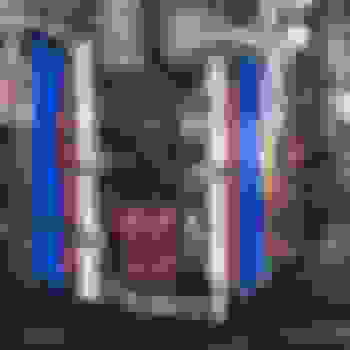
Dimensions of Black Label Transmission which except for Throwout Bearing Inside Diameter are identical to Blue Label Transmission.
1 inch or 25.4 mm...................................... ..................................1.373 inch or 34.87 mm
7.6 inches or 193 mm
1. Sequence of Removing Blue Label Transmission.
A. Remove Exhaust Hangers and three Exhaust Bolts attaching to CATS.
B. Support Engine Under Oil Pan.
C. Remove C-Frame Bolts and ZFdoc C-Frame Brackets.
D. Remove Shift **** and Center Console.
E. Remove Drive Shaft U-Joint Clamps at Differential.
F. Lower Transmission and remove Drive Shaft and C-Frame (a bit tricky removing C-Frame).
G. Remove Bolts from Transmission and Remove Transmission.
H. Remove Clutch Slave Cylinder from Bell Housing and slip Throwout Bearing Pivot to Drivers Side.
I. Remove Bell Housing.
J. Remove Pressure Plate.
K. Remove Pilot Bearing.
The steps A-J are straight forward.
2. Removal of Pilot Bearing.
A 9PC Blind Hole Slide Hammer Pilot Bearing Puller Internal Extractor Removal Kit was used to remove the pilot bearing.
3. Installation of New U-Joints in Main Drive Shaft.
The Old U-Joints were removed by setting the end of the drive shaft in a vice such that the two U-Joints that were removed from the end of the Transmission and Differential sit crosswise on the vice with end bearings still installed. Then with a Open End Socket just a bit larger than the End Caps and using a hammer, pound downward forcing the U-Joint Bearing up and out of the Aluminum Driveshaft collar. The U-Joint can then be removed from the other End Cap and that bearing end removed outward with a punch positioned through the bearing collar just removed.
The new U-Joint is installed by positioning the End Caps in a vice outside the drive shaft and squeezing the two End Caps together making sure the needle bearings and end spacer inside the collar is in position. Lastly, the End caps can be finally positioned (using a socket that fits just inside the collar and hammer) such that the Keeper can be inserted tight against the End Caps making sure the End Caps are not driven allowing play between the keeper and End Cap.
Dana Spicer 5-3613X U-Joints w/Coated Caps for Alum Driveshaft were installed on both ends of the main drive shaft. Universal Joints Source
4. New U-Joints in Half Shafts and New Rear Wheel Bearings were installed (see Post #240).
Dana Spicer 5-3615X U-Joints w/Coated Caps for Alum Halfshafts were installed on both ends of the Half Shafts. SFK BR930024 Rear Wheel Bearings were also installed.
5. Intallation of Rebuilt Black Label Transmission.
ZFdoc Rebuilt 91' Black Label ZF S6-40 Transmission was lifted into place using a Harbor Freight 800 lb Capacity Transmisison Jack.
Transmission Jack
The Transmission Jack works perfectly with the ZR1 on KwikLift18 inches off the ground (Perfect height). The 800 lb Capacity Transmission Jack has roll and tilt adjustments for a perfect match when locating the transmission on the Bell Housing (Clutch depressed last 2 inches of installation). The transmission (on Transmission Jack) can be rolled under KwiKLift from the front as the shifter will clear the cross members and bell housing/oil pan (slipped along side of oil pan).
6. Test Drive
Went for a test drive with several stops at 25 mph wearing off the Black Powder Coating from the Wilwood Rotors. Then some high speed stops and even some speed shifting. WOW....that ZFdoc Black Label shifts so crisp and easy it is amazing when compared to Stock ZF S6-40 Transmissions. ZFdoc Rebuilds are recommended for anyone having Transmission issues and for those that want the best shifting Transmission available for the ZR-1.
And if you want to STOP QUICK.......Wilwood Rotors with C5-Z06 conversions are the way to go
The PCV hose connected under front of plenum (Vacuum source) is connected using SS braided hose to an Oil Catch Can external to the engine which Oil Catch Can is connected using SS braided hose to the dual PVC valves hard line located at the rear of the plenum. The Oil Catch Can is located on the drivers side under the drivers side head light.
The two hose fittings are (Hose End, Swivel, 90 Degree, 6 AN Hose to Male 1/4 in. NPT, Aluminum, Nickel) and the 1/4 NPT is screwed into the Oil Catch Can 1/4 inch NPT threaded holes Swivel, 90 Degree, 6 AN Hose to Male 1/4 in. NPT
The Elite Engineering Oil Catch Can does not come with the fittings cited herein. Replace the fittings of the Elite Engineering Oil Catch Can with the two SS 90 deg 6 AN to Male 1/4 NPT pipe fittings cited herein.
The short SS Braided Hose section connected to the Plenum PCV vacuum is 24 inches long. The longer SS Braided Hose section connected to the PCV connector is 36 inches long.
The INJ1 Fuse was blowing shutting down the engine. This issue was solved by replacing the Coils and/or closely inspecting and jiggling ALL DIS Connectors, Coil Connectors and Injector Connectors including the Injector Wire Harness.
1. INJ1 Fuse blows and Engine is Dead in Water (1995 ZR-1).
I have established Ohms down stream of fuse is 1,200 Ohms with engine off and key off. When fuse blows Resistance is .6 Ohms more or less. And stays that way until engine cools down or I mess with components and connectors under the Plenum.
Disconnected DIS and resistance goes up and stays up to 1200 Ohms.
Of interest and indicating where the INJ1 issue might be......... was last time watching the Ohm meter measuring down stream electrical resistance from INJ1 fuse while disconnecting electrical under the Plenum (INJ1 had failed and showed zero ohms on down side) the Ohms came back as I disconnected the 14 pin DIS connector.
The 14 Pin DIS connector (8 pins are used) has 4 wires with original (stock) mechanical crimped splices down by rear of block just before large Wire Loom. I disconnected the large Loom clamp and raised the loom just even with the windshield wiper motor. I cut those mechanical splices and slipped heat shrink on the cut wires and then soldered the wire ends. Heat shrink slips over the soldered splice and with some heat will insulate the splice. I then put it back together temporary and took a ride with no issues. I then removed the Plenum one more time and installed new wire looms on all electrical wires.
Installed New Red Wire Looms on Coil Driver wires, EGR wire. secondary MAP wire, and the Crankshaft sensor wire connected to rear of DIS. Just cleaning up all wiring (Some of the New Wire Looms contained multiple Connector Wiring). Installed new wire looms on Injector Wires as well.
The key is to install the wire looms such that no connector is under any kind of tension at any time and with the wire looms on each wire there should be no wire contact with anything under the plenum.
Did check secondary operation by grounding Pin 17 on the ECM Green plug. With key on and with finger over vacuum line going to secondary Map sensor the secondary canisters functioned perfectly.
New Coils........................................ ................................New Wire Looms (Red)
3. DIS Substitute by years.
Regarding DIS substitute by years.......I have two additional Experts helping me (Marc and Anonymous) who have pointed out that the first 500 or so 90's used a DIS module that has a part number that ends in 37. Those units only function with a brass shim under the crankshaft sensor. These modules will work in later cars as long as the crankshaft sensor is modified with the brass shim. After that initial run of 500 or so the DIS are interchangeable with later year LT5s. Crankshaft Position Sensor Shims
4. Crankshaft Sensors are NOT all the same.
Also it was pointed out by Marc regarding installation of a new Crankshaft sensor....some new crankshaft sensors have manufacturing faults. One new manufactured crankshaft sensor had the magnet installed backwards in about 2005. There is no spark with that magnet installed backwards. Some currently available new crankshaft sensors have a metal bracket that prevents the sensor from seating correctly in the LT5 block. This sensor is positioned in the block in such a way that the LT5 is difficult to start at times.
5. Use of mechanical electrical splices on other LT5 wiring harnesses.
Just for your additional information.......I also found original stock mechanical splices on the Drivers side Injector Wire Harness between the last injector by the fire wall and main wire loom captured in the Clamp attached to rear of block. I did not replace those original Injector Wire Harness splices simply because it is NOT an easy job to get down in that area with a soldering gun, wire stripper, Heat gun, or electrical tape. The mechanical splices on the Injector Harness did look well separated.
I did manage to replace four of the 14 Pin Connector Splices between the 14 Pin Connector and the main wire loom captured in the Clamp attached to rear of block. I removed the mechanical splices and used Solder, Heat Shrink, followed by electrical tape to connected the exposed ends of each wire (overlapping the bare wire ends about 3/8 inch on each side of the splice). The solder took very well saturating the two bare wire ends. One more point........These four splices on the 14 Pin Connector Harness each had two wires coming from the main wire harness within the clamp attached to the rear of the block going into one wire going on into the 14 pin DIS Connector. The only way to do that is to splice the wire.
6. Use of mechanical electrical splices on other LT5s.
I checked another LT5 wire harness I have on the wall (from a 90 or 91) and yes....it also contained these splices. The splices are interesting as they are swedged/crimped metal clips that are crimped over overlapping ends of bare wire as you can see in the photos. These Crimped wire ends are in turn wrapped with a silly cloth wrap about 1.5 inches long that is relatively loose and can be removed by cutting lengthwise with razor blade. Keep in mind this is a 95' with more going on under the Plenum (EGR and Secondary MAP).
6. Could the mechanical electrical wire splices have caused INJ1 fuse to blow? I am not saying these splices caused INJ1 to blow as it appears only a shorted wire could do that. The splices although in somewhat poor condition did not appear to be in contact with associated spliced wires. I will say when I got done soldering the overlapping ends and sliding heat shrink over the splice with some heat it is like night and day on the continuity of the resulting splice compared to the original mechanical splice. And.....most importantly, the stripped wire ends (stripped 3/8 inch on each overlapping wire) took solder very well saturating all strands of the bare wire ends.
1. First we identify the various Electrical and Vacuum Connections associated with the Plenum.
2. We shall assume the Secondary Vacuum System under the Plenum and the Coils/Spark Plug Wires are connected. We shall also assume the two Coil Electrical Connectors are connected. We shall also assume you have TB Coolant Blocked at each Injector Housing. It is also assumed the Fuel Tank Cap is loose and the two Fuel Lines are disconnected from the Fuel Pressure Regulator plumbing.
3. Start by setting the Plenum in place (Plenum gasket will be inserted later) and slipping Vapor Canister line through Plenum Runners on passenger side which takes a couple seconds.
4. Tip Plenum Up in Front and install two Coil Driver Connectors, EGR Connector, Secondary MAP Connector and Secondary Map Vacuum which takes 30 seconds.
5. Lower Plenum in front but not too low and install the Vapor Canister Vacuum Line which takes 10 seconds.
6. Slide Plenum forward an inch or so and install the 14 Pin DIS Connector and the Crankshaft Position Sensor on rear of DIS which takes 20 seconds.
7. Raise and lower front of Plenum and install the left and right Cam Cover Vents Hoses which takes 20 seconds.
8. Install Secondary Vacuum and Cruise Vacuum Connectors and install IAC and Air Temp Connector which takes 20 seconds.
9. Install TPS connector and insert Plenum gaskets and Plenum Bolts (12) as required which takes 30 seconds.
10. Using a Drill with 6mm Allen socket inserted, tighten 12 Plenum Bolts which takes 30 seconds.
11. Install MAP and MAP Connector and MAP Vacuum at rear of Plenum and install Fuel Regulator Vacuum at rear of Plenum which takes 30 seconds (Also insert PCV Valves into the PCV Hose).
12. Finish by installing Brake Booster Vacuum and Throttle Cables as well as corrugated air Intake between Air Horn and Air Filter which takes 30 seconds.
13. Check all connections and reconnected the two Fuel Lines to the Fuel Pressure Regulator Plumbing. Connect EGR (two 8 mm bolts) and tighten the gas cap which takes 30 seconds. We just installed the Plenum in 240 seconds or 4 minutes
Marc's latest BMCBG Chip for 93'-95' is version 4. Marc normally does not need the stock chip to which you attach his upgrade chip.
You burn 91 Octane or better. Since switched to 87 Octane Chip.
You remove the blue part and attach original chip to Marc Haibeck chip which is then inserted into the original slots of the ECM. You have to use shorter screws for the ECM Chip Cover (I use SS 6-32 x 3/8 inch Allen Head screws with the original washers).
K40 (UN3000/SW/SWL) Front and Rear Radar Detection System
Directional Awareness � Know exactly where the police are at all times � dual radar receivers provide directional awareness and increased range to keep you protected from radar threats � two discreet LEDs indicate front (left light) or rear (right light) radar, accompanied by an audio alert that states �front� or �rear� as well as the specific band of police radar. K-Band Filter � The RL360i intelligently recognizes and rejects radar-based safety features from other vehicles and your own vehicle so you remain focused on real radar threats. Traffic Sensor Filter � The RL360i will reject alerts from traffic flow sensors usually encountered during highway driving.
LED Brightness Control -- 5 customizable LED brightness settings. Allows you to adjust the intensity of the LEDs depending on the time of day or your visual preference.
The 1995 had a small oil leak on the front Passenger Side Oil Pan 10mm Bolt appearing to be loose Oil Pan Bolts on the front including the four 8mm Oil Pan Bolts. What actually was leaking oil (just enough to keep that 10mm Oil Pan Bolt wet but nothing dripping on the pavement) was the Loose 6mm Bolts on the Oil Pressure Regulating Valve Cover.
On the 1995 ZR-1 the Oil Pressure Valve Cover Plate is impossible to get to from above because of the EGR. But....one can get to that Cover Plate from below by removing the Passenger side strut that the Passenger Side Motor Mount is bolted to (no pressure on that strut from motor mount). Remove two 15mm bolts toward front and two 13mm bolts on frame rail passenger side. Remove 18mm Nut from Motor Mount Stud and drop the strut. The Oil Pressure Valve Cover Plate can be easily seen toward front where Strut was positioned. The bottom 6mm bolt is easy to unscrew and the top 6mm bolt required a vice grips gripping an 8mm open end to tighten. Both 6mm Bolts with 8mm Heads were replaced with 6mm Bolts with 10mm Heads.
The Trick to STOP oil leaks from the Oil Pressure Control Valve Cover plate.
I replace both top and bottom 6mm x 16mm bolts (8mm Heads) with 6mm x 16mm Flange Bolts (10mm Heads) (Ebay and as pictured above) that have a 10mm heads for a 10mm Box or ratchet Box wrench. It is a lot easier to tighten a 10mm bolt head than an 8mm bolt head which sometimes strips in the small 8mm box wrench. I used Red Loctite on the 6mm x 16mm with 10mm Head Flange Bolts. No need to remove the Oil Pressure Valve Cover Plate or associated gasket.
Two 6mm x 16mm with 10mm Head Flange Bolts installed in Oil Pressure Regulator Valve Cover (10mm Heads)
replacing original 6mm x 16mm (8mm Heads) Bolts. Top 6mm Bolt shown before tightening with 10mm Box Wrench
The Correct Size Alternator Pulley is about 2.75 inch OD on the face....This ALL Aluminum Pulley is very light and just tad larger yet very close to 2.75 inches diameter. It is a little Pricey from Summit Racing. The Installation is very easy with my 15/16 inch modified Combination Wrench and 5/16 inch Allen Wrench.
The MCH-208 is the same Diameter as the Stock Pulley.Actually the MCH-208 is just a tad larger diameter.
Use a 1/2 inch Adapter on Socket Wrench to Unload the Belt Tensioner when removing/installing Pulleys.
The Offset of the MCH-208 is identical to the Stock Pulley.
The Stock Pulley has a removable Offset Collar which is NOT used in the installation of the Aluminum Pulley.
This Pulley can be installed without removing anything including the Serpentine Belt (except the Original Alternator Pulley).
Look for MCH 208 on Summit Racing MCH-208or Ebay MCH-208
Oh.....by the way.....I just invented a New Way to install the Serpentine Belt......Remove the Alternator Pulley (takes 1 minute) and position NEW Alternator Pulley inside Serpentine Belt and lift up the Alternator Pulley and Serpentine Belt with Belt Tensioner compressed (Keep Serpentine Belt aligned with Belt Tensioner Pulley). Now just slip the Alternator Pulley onto the shaft (very easy to do and plenty of play) and tighten up the 15/16 inch Alternator Pulley Nut.
Lastly......install the Aluminum Alternator Pulley Cap with the three Allen Head Bolts provided with just a little torque as they are threaded into Aluminum.
If you look closely, you will notice also my ALL Aluminum Belt Tensioner Pulley.
The inside rim of the Aluminum Alternator Pulley is about 1/16 inch or less from the fan but not touching the fan.
After a New Fluidyne Radiator Install I thought I should go all the way and put in a New 180 deg Thermostat. Marc answered a question I had in that regard. The thermostat for all LT5's is the same. The temperature rating is 180 degs F. In detail, the thermostat begins to open at 175 deg and is fully open at 185 degrees. A thermostat with over 50k miles generally opens 5 degrees later and opens about 85%. The 180 deg versus the 160 deg thermostat or no thermostat
So.....why not. I checked my New 180 deg Thermostat in Hot Water and it started to open at approximately 175 deg. Ready to go...and I had my Post on LT5 Thermostats on hand
Well......the New Fluidyne Radiator Drain Port worked perfectly. Now to separate the Thermostat Housing Halves. OOPS!!!!!
It all went down hill from there on.....
1. Bottom Bolt on Thermostat Housing was frozen Solid. Broke it off.
2. Had to remove Belt Tensioner, to get my hands in to move AC Dryer and to get to Lift Thermostat Housing.
3. Also removing Belt Tensioner gives access to the Spring Clamps on both ends of the Radiator Hose connected to Water Pump.
4. The Hose from Water Pump to Thermostat Housing is the only Coolant Hose I have yet to replace.
5. Disconnected Passenger Side hose to Heater Nipples on Thermostat and got it free (what a corroded mess).
6. Cut the Coolant Hose going over rail to Thermostat Housing.
7. Finally got Thermostat Housing up and out after moving the Top Coolant Hoses connecting Each Injector Housing.
8. Once the Thermostat was lifted up so I could get to the Drivers Side Heater Nipple....Disconnected that Heater Hose.
9. The Water Pump Spring Clamp was completely turned impossible to get a pliers on it so I used an Air Grinder.
10. Oh...ya.....Got the Hose Clamp cut but all I did was cut a piece out that allows you to compress the ends together. Now what a mess :o
11. After a couple hours with a razer blade and screw drivers finally got that hose off the water pump.
12. OOPS.....forgot about the frozen Bolt in Thermostat Housing which I had to use Acetylene Heat.
13. After heating finally got the stud showing to move back and forth and 30 minutes later got the stud out of the Thermostat Housing.
14. Chased the Threads in the Thermostat Housing.
15. The Drivers Side Heater Nipple on the Thermostat Housing has an "O" ring and the inside where the "O" ring resides was corroded.
16. Thanks to Jerry having much more foresight than myself I ordered a New and Improved Thermostat Housing Heater Nipple.
THIS ALL STARTED THIS MORNING AT 9:00AM AND ENDED AT 5:00PM THIS AFTERNOON !!!!!!!!!
This should be titled "You think you got Problems"
Oh......Checked that Stock Thermostat (must have been stock since the bolts in the Thermostat Housing were frozen solid) for Function.
I suspect it be a 180 deg Thermostat. It started to open at 195 deg and never opened all the way as far as I could tell.
So....what started off a great day with great idea had some tuff spots but ended up solving several issues including Corroded Thermostat Housing, Old Water Pump Hose that needed replacement, Corroded Heater Nipple on Thermostat Housng, and finally found out that what Marc had suggested about Thermostats was exactly what I found with the poor condition of my Stock 180 deg thermostat.
Installed the NEW Jerry's Thermostat Heater Nipple on the Thermostat Housing. After Cleaning up both Heater Nipples and with the New Heater Nipple installed I popped on the Heater Hoses. I acutally used just a tad of Permatex on the nipples for ease of insertion and a bit of additional leak protection. I also installed one new Water Pump to Thermostat Housing Coolant Hose. Fired up the LT5 after filling with Coolant and took it for a spin. No Leaks and Coolant Temperature stayed about 15 deg cooler than with the worn out Thermostat that actually opened at 195 deg (the New 180 deg Thermostat opened at 175 deg).
Just a Heads Up......if you ever have to remove the Thermostat Housing for any reason, have on hand one of Jerry's New Heater Nipples to replaced the old Heater Nipple on the Thermostat Housing. Jerry's New Heater Nipple
As an aside See Item #9Post 237 - Blocking TB Coolant, Fluidyne Radiator and Thermostats..........My thinking is that the whole purpose of the Dual Opening Thermostat Housing (Thermostat can open at the Temperature side or on the other end at the Pressure side) is to keep Radiator Pressure to acceptable limits. In other words the Thermostat functions when the engine is cool and when the engine is at high rpm.
When the engine is at high RPM, the Bypass on the thermostat will be open completely do to the water pump developed coolant pressure on the bottom of the Thermostat. This Higher pressure being developed at the bypass end of the thermostat because the Thermostat is closed on the Temperature end or because the high water pump RPM is developing too much pressure on the radiator on the Bypass end of the thermostat.
In other words the Thermostat can open on either end (one end temperature controlled and the other end differential pressure controlled).And even it the Temperature End of the Thermostat is fully open, HIGH water pump RPMs may develop greater pressure than the radiator can stand on the Bypass End and the Thermostat would then open on both ends to allow more coolant to recirculate rather than ALL of the coolant flow being forced through the Radiator . 7,000 Engine RPM does that to you
2. Some Thoughts regarding the Thermostat Housing
1. It does not make any difference if you use a 160 deg thermostat or 180 deg thermostat....they both are fully open at 185 deg.
2. I makes no difference if you drill small 1/8" holes in the thermostat flange as the additional flow area (.0123 square inches) is only 1.5% increase per hole over the Thermostat Full Open area of .785 square inches.
3. The Heater Circuit is open at all times even on a cool engine after start as the heater will be the first to get warm coolant.
4. On a very cold day with the heater on and Interior Fans set at Ten, the Heater Core with significant coolant flow could cool the engine for a significant amount of time before the main temperature controlled end of the Thermostat on the radiator side opens. The engine coolant mixed with some air would still expand into the radiator and to the coolant over flow below the passenger headlight.
5. If you want to cool your engine below the temperature controlled thermostat on a cold day or cool your engine a bit more on a very hot day, run your Heater with Interior Fans set at Ten using Outside Air (not recirculate) with windows open. The additional Coolant Flow through the Heater could be as high as 14% of the total coolant flow with 3/8 inch ID Heater Hoses.
6. The bottom of the thermostat on engine side opens at differential pressure of 5psi when open 1/2 inch allowing coolant to bypass the radiator (Marc Haibeck Testing).
7. When the thermostat has not reached opening temperature (175 deg) the coolant recirculates through the bottom of the thermostat at a pressure of 5psi since the coolant flow through the radiator is blocked.
8. Always use original green coolant GM 1825M.
In your drawing, you show the coolant flow path from the Injector Housing Coolant Manifolds to the Hot side heater hose and mention the "Recycled Coolant opens at 5psi over pressure". That feature is a small disc and spring on the "back" of the thermostat. The disc is what creates a differential pressure across the heater so that there will be flow. That disk has a notch (opening) in it so that there is always some coolant flow in the system. I believe that notch will affect the engine temperature at low engine rpm and low car speed.
Jim
Yes....I calculate the notch areas to be about the same area as heater hose area or about 14% of full Thermostat open area. Each of two notches being about 1/4 inch x 1/4 inch. That disc does create the differential pressure to force hot coolant through the Heater Core. According to Marc's test the differential pressure created by the disc is 5 psi at a disc opening of 1/2 inch.
As some may not know.....that disc is what keeps the radiator pressure at acceptable limits at high rpm. As the head loss through the radiator and thermostat increases with coolant flow the disc will open further at pressures over 5psi to a point that coolant recirculating flow path is completely open. You do not want to operate in that condition at very high rpms on HOT days as the coolant flow passing through the radiator is diminished compared to coolant flow recirculating (actually more coolant flow through radiator because of higher water pump flow but more coolant recirculating within the engine which overall is less engine cooling).
One of the questions always asked is where can I find a shop that can work on my Z. Of the many resources we have here a National list of Z (LT5 specifically) competent shops is not one of them. I’m not sure the list over at ZR1.net is up to date or complete.
H
I think the old question will remain "Does anyone know in my area a competent shop to work on my LT5/ZR1?" The ANSWER is usually NO....that kind of shop does NOT EXIST within driving distance that would solve their ZR-1/LT5 issues.
Trouble is....unless you want to drive several hundred miles (or 500-1,000 miles) with a ZR-1 that has issues....this information will not help much (so get out your tools).
Most issues are relatively easy to fix and most want someone that is familiar with the LT5/ZR-1 just to take a look like Jim for example who has set up a help location for the WAZOO folks. I have helped several within 50 miles or so for example and that handful is ALL that ARE within say 100 miles of where I am located in SD or CA
The BEST help is actually the Forums where in asking questions one can find out who is helping and where they are located. And.....most importantly....GOOGLE that will take many directly to the Forums Stickys wherein they can then Join The Forums. Once on the Forum they can then easily locate someone that can possibly take a look at their ZR-1/LT5 issues.
Or learn themselves how to work on their ZR-1s/LT5s as most issues are easy to fix.
The Market is driven by those that buy a ZR-1, cannot fix small issues, and cannot locate a shop.....so sell relatively low.......for me as a buyer
But then once the ZR-1/LT5 is easily restored (A two day job consisting of removing components and fluids, cleaning, maybe modifying and replacing components and fluids) those same folks are scared to get into another ZR-1 because they do not believe once the small issues are fixed you can drive another 100,000 miles without doing much other than possibly removing a plenum (takes 10 minutes after some simple modifications) to check on things or replacing changing the Oil or changing a light bulb
An Example is changing the Oil Filter on a ZR-1/LT5 which on the ZR-1 if you leave it sit overnight is absolutely the easiest to change the Oil Filter than on any other car or truck I have had. And the Infl Rest does not mean the Air Bag will not deploy...it only means the sensor is not grounded. And it only takes a few minutes to actually ground #17 ECM Red/black stripe wire on Plenum to actually see the Secondaries functioning with a flashlight.......In Other Words....the ZR-1/LT5 is very easy to maintain
For anyone wondering about ZR-1 windshields, the non-ZR-1 windshields will fit and can be used on ZR-1’s. Unless you want your ZR-1 to be completely stock.
The reason why ZR-1’s came with a shade type windshield is due to this. The LT5 engine takes up more space in the engine area. This caused GM to use a smaller AC unit. So GM thought some high temperature locations in the US might be too hot for the smaller AC units. This is why ZR-1’s had the shaded windshields to help cool the interiors more.
So if you are not concerned about your ZR-1 getting too warm in your interior, get the standard C4 windshield if you need a new windshield.
That is very interesting information
I measured specifics on my 1990 (L98} and 1990 ZR1 windshield........
The clear glass area for radar is the 10" area on the 1990 LT5 and for the 1990 L98 the glass is clear across.......
Everything measures the same regarding the radar cutout.......as there is no radar cutout on the 1990 L98........
The VIN number clear area is identical for the 1990 LT5 and 1990 L98....... DW01112 and DW01085 Windshields are the same in this regard. (3-1/2" wide across the windshield and 3/4" high opening)
Both LT5 and L98 VIN area openings start 9 " from tip of hood.......
Both VIN Openings are 2-3/4" from bottom of windshield in the colored area on the 1990 LT5 and 1990 L98........
On the 1990 L98 it is clear glass all the way across the windshield above the lower 4-3/4 high Dark colored area.....
On the 1990 LT5 it is mild tinted (Except the Radar Cutout is clear) glass all the way across the windshield above the lower 5" dark colored portion........
The white paper on the 1990 L98 is clear glass all the way across the windshield......
ZR-71 Hit The Nail On The Head
Originally Posted by Preshenne
What is the DW01112 windshield? Safelight says it is correct for my 95 ZR-1 VIN.
From what we are discussing it appears the DW01112 will be fine except it is not tinted (not Solar)......as ZR-71 describes in detail.........
You can tell that from the photos below wherein you can see a lot easier through the windshield of the L98 on the right......
No Need for Radar Cutout on L98...........
The Windshield DW01112 is NOT Tinted (Solar) like the originalDW01085Solar Windshield installed in the 1990-1995 ZR1s......
Apparently that is the only variation between the DW01112 and DW01085 Windshields as ZR-71 describes above..... Original 1990-1995 ZR1 Windshields were Solar.........the 1990 L98 windshield is not Solar....... If you use the standard DW01112 Windshield you can place your Radar or Satelite Watching Devices anywhere on the Dash Post 50 - Replacing the Windshield and Wiper Motor
Additional Detail Information regarding Tinted ZR1 Windshields......Tinted ZR1 Windshields
................................1990 LT5..................................... ..............................1990 L98........................... Last UPDATE of post 254 Mar, 2024
FX3 Selective Rid Control TIPS
FX3 Actuator Rebuild TIPS
In regard to applications of FX3 Shocks 90-91 and 92-later....... You can't just change out the gear on top as entire rod needs to be changed due to the valving holes. You can use 92 FX3s in 90-91 Application if you upgrade to the newer controller.
Seethis from Captain Z
Please take a moment to inspect the small metal gear located on the top of the shock. Often they are broken and must be replaced before the fx3 system will be restored to working order. We have original equipment gears in stock for 1989 to 1991. We have replacement gears for 1992 and later models in stock also. These gears are made of steel finished in yellow zinc dichromate. There are two different gears used on the shocks in the fx3 system. The difference is in the size of the stop located along the lower edge of the gear. The year of your Corvette determines the type of gear used. See photo below.
Visually inspect the gear for breaks and for cracks. Also the gear should not be able to turn in complete circles without stopping. If you can turn it continuously without hitting the stop then it is broken and must be replaced. The gear can be replaced in either position without affecting the operation of the shock.
From this it appears to me the setup of the FX-3 is self aligning in all regards...........just want to make sure.
Originally Posted by Dynomite
Got a new front actuator on Ebay and installed it with shock gear centered. Appears the positon of shock gear makes no difference because the actuator does a self alignment on startup. Got rid of Service Ride Control warning ......it went away immediately and never returned
When the ignition key is turned, the system will do a check to be sure it is working properly. The service ride control light should come on momentarily and then go out if all is well. If the light stays on then the system most likely has problems.
The two following observations suggests FX3 Bilstein self alignment IS what I think it is........
Originally Posted by We Gone
I've had my front actuator motors off every time I clean the front suspension, blow the grit out of the cups and put a drop of gun oil on the shock gear even turn the gear and never paid attention to the position when I put them back on with 0 issues.
Originally Posted by Jagdpanzer
I changed out my front shocks recently and all I had to do was carefully reinstalled the actuator by rotating it back and forth as it went down on shock the to make sure the actuator and valve gear teeth properly engaged. When fully inserted the splines on the outside of the actuator cap will lock into the metal cup on top of the shock and the retainer clip will insert easily then. As mentioned above when you turn the ignition key on the actuator cycles in both directions sensing the location of the valve hard stops by the resulting increase in current draw when the stops are reached. Then you’re ready to go. If for some reason the control system cannot find either of the valve hard stops (in case of broken gear) or senses the calibration time is taking too long it will trip the “Check Ride Control light”.
The 90' wheels (rims) are called Salad Shooters.
The 91' wheels are the same through 93' and are called Saw Blades with the 93' being machined.
The 94' and 95' wheels are called A-Molds.
And even though the Stock Rims may look different by years all Stock Rims are interchangeable for ALL Years 1990-1995.
1990 ZR-1 and 1990 Standard...................1991-1992 ZR-1...........................1993 ZR-1 .............................
.......1994-1995 ZR-1 The 90' Salad Shooters and 94'-95' A-Molds (Stock or After Market) will clear C5-Z06 with Wilwood Rotors Brake Conversions. Stock A-Molds have JWL in the 2nd window clockwise. Saw Blades will NOT Clear C5-Z06 Brake Conversions with Wilwood Rotors without the use of spacers.
For the Standard 1990 Corvette and the 1990 ZR-1 Corvette the Front Salad Shooters are Identical on the 1990s.
Here is Simple.............simple in that no mess and no fuss with the ZR-1s for 4 months
1. Install the Battery Disconnect Switch and Disconnect the Battery.
2. Fill the gas tank.
3. Make sure antifreeze is good for at least -15 deg F (3-1/2 ***** floating).
4. Park the ZR-1s on floor mats to prevent condensation on a bare unheated concrete floor.
5. Use about 5 sheets of bounce poked into the Plenum Runners.
6. Use a Car Cover to keep the car clean which adds to the heating effect.
7. Do NOT start the car during the winter storage.
8. Move to California for 4 months and Drive the CA ZR-1s.
I Disconnect Battery Cables (Negative Cable on ZR1) when vehicles are sitting over a couple weeks. This includes ATVs, Tractors, Trucks, Cars and they ALWAYS fire right up as if a NEW battery when the battery cables are reconnected. CHARGE BATTERY BEFORE DISCONNECTING CABLES.
Keep the fuel tank filled to the top to suppress water condensation.
I use NO SNAKE OIL treatments in gas/diesel tanks but DO FILL FUEL TANKS before any over winter storage. I have noticed on carbureted ATVs that the jets WILL GET GUMMED UP over a long period of sitting where the gas in the carburetor bowel is allowed to completely evaporate.
In cold climates make sure your coolant antifreeze (GREEN for LT5) is at proper concentration for coldest temperatures.
I do use BOUNCE if for no other reason the interior is FRESH in spring. Assisting BOUNCE make sure the ZR1 interior has NO access for mice and keep ZR1 covered so interior is DARK as mice look for lighted access points.
A moisture barrier will not stop a concrete floor from sweating. It will stop the mitigation of ground water through a slab if done correctly. Sweating is caused by a combination of concrete temperature and weather conditions. If the concrete is cold enough and the temperature and humidity high enough the slab will sweat, regardless of a barrier. I use GETRUNG Flooring on Ebay. SeeShowroom Mats for ZR-1s
A Typical Top End Restoration of an LT5 will definitely increase reliability when driving and if done properly will actually get reliability close to 100% for those Long Drives. A good LT5 Top End restoration will usually add years of fun driving without any issues.
Once the basic stuff is accomplished (A Top End Restoration including Starter, Alternator, Vacuum System and Valley clean up).......the ZR-1s will run forever. The Top End Restoration usually takes three days.....disassembly and cleaning the first day, Thinking the second day, and Reassembly the third day. The Replacement parts are the normal (Injectors 50% of time, Vacuum System 25% of time, Coils 75% of time, Plugs 100% of time, Plug wires 100% of time, Secondary Linkage (100% of time because it is so cheap to replace). Also 100% of the time I include New Serpentine Belt, New Injector "O" Rings, SS Plenum Allen Bolts, New Charcoal Canister and New PCV Hoses (includes all 4), Fuel Pressure Regulating Valve Vacuum hose, Map Vacuum hose. The rest of the restoration consists of degreasing, wire brushing. pressure washing, painting, and final adjustments including INFL REST reconditioning. Almost forgot.....New Radiator Hoses and New Aluminum Radiators (Fluidyne, Dewitt, Ron Davis), Differential Drain Plug, ZFdoc C4 Beam Plates and new 180 deg Thermostats 100% of the time. And......Haibeck CHIP 100% of the time.
This ALL after a basic Compression Test.
And....And.......Always BLOCK TB Coolant at the Injector Housing and Install Differential Drain Plug as well as ZFdoc C4 Beam Plates.
And.....Always install SS Braided Oil Coolant Hoses as well as Billet Aluminum Pulleys (Water Pump, Power Steering, Belt Tensioner).
And......ALWAYS Change ALL Fluids for a good starting point.
And.......Sometimes install C5-Z06 Calipers with Wilwood Rotors and SW Headers/Exhaust (That Combination goes together).
Sometimes install a new Oil Pan Gasket just to keep any and all oil off the garage floor. This includes checking the Oil Pressure Regulating Valve Cover Plate.
I do some other stuff like the guy who has 5 ZR-1s just because working on the LT5/ZR-1 is soooooooo much fun.
1991 ZR-1 restored with 500+ horsepower
As I recall.....the guy with the 5 ZR-1s picked them up for between $14K and $19K (19K for a 95 in mint condition).
Summary of ZR1 Restorations including 95' Crate Engine
Summary of ZR1 Restorations including 95' Crate Engine
A. Under the Hood
1. The first test I always do on a LT5 is a compression test if it runs good or not (210-220 lbs within 5 lbs each cylinder). This verifies that the valves are in good shape as well as rings, pistons......
2. from there I verify the vacuum system by noting the vacuum pump cycles.........I then know the condition of the vacuum system and valves.
3. I make sure Oil Pressure is normal and always check for all External Oil and Coolant Leaks.
4. Before I remove the Plenum I check ALL Codes to see the minimum requirements of a Restoration (I use my ALDL Code Reader to check and erase Codes on 90'-95' ZR-1s).
5. I then remove the Plenum and check Injector Resistance (I usually install NEW Injectors and Injector "O" Rings).
6. If the engine was not running smoothly, I seriously consider new Coils.
7. I always recondition the starter Solenoid and Starter Armature Bearings.
8. I replace old leaking Vacuum Connectors as required.
9. I then install New Plugs and often New Plug Wires.
10. Before I replace the Plenum I always Block Injector Housing TB Coolant.
11. I also replace gaskets (including the Crankcase Cover Gasket).
12. Re-install Injector Housing Bolts were there were indications of oil leaks.
13. Use nothing on the New Plenum Gasket and tighten the Plenum Bolts snug with one extra tug on Socket since no Coolant is involved after TB Coolant Blocking.
14. Raise the Plug wires to the TOP of Injector Housing to get the Plug Wires off the top of the rear of the Cam Covers.
15. Jerry sends me NEW PCV Connections and MAP Hose as well as New Fuel Pressure Regulator Vacuum Hose.
16. I usually install a rebuilt Alternator.
17. ALWAYS replace the Serpentine Belt.
18. Replace the Belt Tensioner Pulley.
19. I Also......ALWAYS replace the Thermostat with a NEW 180 deg Thermostat.
20. ALWAYS replaced the Stock Radiator with a multi core Aluminum Radiator.
21. Always replace the Air Filter for the Intake.
22. Install a Intake Screen for air going through the Oil Cooler, AC Condenser and Coolant Radiator.
23. There are other items I recondition such as valley Drain and Check ALL Electrical Connectors to DIS.
24. I Replace Crankcase to Injector Housing Vent Hoses (two).
25. Usually replace the Secondary Port Throttle Linkage NEW from Jerry.
26. I sometimes install an Oil Catch Can.
27. I ALWAYS replace the Charcoal Canister.
28. I sometimes Install Z06 Brakes with Wilwood Rotors.
29. I have installed ZFdoc Rebuilt Black Label Transmission with short shifter in a 95' ZR1 (all I can say is WOW!!!).
30. I ALWAYS Install Marc Haibeck Latest Performance Chip which in particular changes the operation of the Coolant Fans and Engine Spark Timing.
31. Check and Install New Spark Plugs as necessary.
A. Blow all debris off Cam Covers using 90-100 psi Air Pressure.
B. Pull ALL Rubber Spark Plug Boots.
C. I use a rolled up sheet or tube of paper towel to swab up the oil if any inside each Spark Plug Port.
D. You do not want to remove the spark plug first as there may be some debris you do not want to fall into the cylinder.
E. After ALL Oil is eliminated in Spark Plug Ports.......Use the 90 psi Air to blow into each Spark Plug Port.
F. Use a tad of White Grease around each raised rim (just below the Top Rim) of each boot to make installation easy.
B. Outside Engine Compartment
1. If INFL REST Codes I ALWAYS Re-install the Air Bag Accelerometer (both sides) to make sure of a super Ground Connection.
2. I Sometimes Replace Front Shocks.
3. ALWAYS Check Tow-In Wheel Alignment to assure about 1/8" Tow In (after braking going forward).
4. ALWAYS Install Fresh NEW Fluids ALL AROUND.
5. Install Differential Drain Plug.
6. ALWAYS Install ZFdoc's (Bill's) C4 Beam Plates and Re-align the C4 Beam with proper torque on each end.
7. If tires are original, I install NEW Tires (Nitto NT 555 Extreme Performance on Front and Nitto NT 555R Drag Radial on Rear).
8. I did have one new windshield installed by Safelite provided by Dave (which windshields are perfect).
C. Bling
Water Pump Pulley
Belt Tensioner Pulley
Power Steering Pulley
Oil Filter Cover
Power Steering Reservoir Cover
Brake Fluid Covers
Windshield Wiper Fluid Covers
Coolant Overflow Covers
Radiator Cap Cover
Throttle Cables Clamps
Fuel Line Bracket
Dip Stick Handle
TB Coolant Cover
 06-26-2016, 04:01 PM