Looking for distance from bell housing face to pilot bearing face
 01-11-2017, 02:25 PM
#1
Melting Slicks

Thread Starter


Trying to determine the engagement depth of the ZF transmission input shaft into the crank pilot bearing. What I need is the distance from the bell housing face to the face of the pilot bearing. Bearing needs to be at correct depth into crank (approx. 15mm).
Thanks!
Thanks!
 01-11-2017, 05:16 PM
#2
Tech Contributor


Measure from the Transmission face (mating to Bell Housing) to tip of transmission input shaft. The engine end of the pilot bearing should be inserted just a bit less than that distance from the face of the Bell Housing.
Last edited by Dynomite; 01-12-2017 at 09:53 AM.
01-11-2017, 06:20 PM
#3
Melting Slicks
Thread Starter
The issue is the general rule of thumb is to drive the bearing until it bottoms on the shoulder inside the crank hub. If you do this I fear it may not be far enough when using a bearing instead of a bushing. The needle bearings start approx. 0.3" in from the face of the bearing.
01-11-2017, 06:35 PM
#4


The issue is the general rule of thumb is to drive the bearing until it bottoms on the shoulder inside the crank hub. If you do this I fear it may not be far enough when using a bearing instead of a bushing. The needle bearings start approx. 0.3" in from the face of the bearing.
01-12-2017, 08:22 AM
#5
Melting Slicks
Thread Starter
I just checked a NOS correct "fluted" and it's .749 total and of course there's a radius involved also. Over at the other forum I suggested how it could be "tailored" I felt for any individual install. I really think it needs to be an "individualized" install. I don't believe you can rely on a measurement from Jim, John, Joe, Dick or Tom.
After replacing the old clutch/flywheel combo with a RAM dual disc with concentric TO bearing, the car now experiences a shudder when starting from a stop in first. It is getting better. Some say that is an inherent trait of dual disc clutches and light weight flywheels but others say it should not do that. I am wondering if the transmission input shaft is not significantly engaging the pilot bearing, if this may be contributing to the issue.
01-12-2017, 08:41 AM
#6
Melting Slicks
Thread Starter
If you are installing a bearing instead of a bushing, the bearing would need to be installed at 0.30" less than that to just reach the needle bearings. I would say you would want at least 1/4" engagement into the actual bearings. So I would install at least 0.55" less than that if possible.
Last edited by KJL; 01-12-2017 at 08:44 AM.
01-12-2017, 08:44 AM
#7
After replacing the old clutch/flywheel combo with a RAM dual disc with concentric TO bearing, the car now experiences a shudder when starting from a stop in first. It is getting better. Some say that is an inherent trait of dual disc clutches and light weight flywheels but others say it should not do that. I am wondering if the transmission input shaft is not significantly engaging the pilot bearing, if this may be contributing to the issue.
If yes I'd be a little more direct and maybe contact Phil "Jagdpanzer" who I believe has this or a very similar clutch and ask what his experience was when "burnishing" (maybe poor word choice) the clutch/flywheel. there are others also. Maybe mention the part# of your f'wheel and clutch components.
I'd think it easier to get someone with a crankshaft on the bench/stand to give you a definite depth to the crankshaft end plug. Maybe solicit a couple depths from others, then form your own opinion as to your install.
Last edited by WVZR-1; 01-12-2017 at 08:44 AM.
01-12-2017, 09:56 AM
#8
Tech Contributor
Dynomite-
If you are installing a bearing instead of a bushing, the bearing would need to be installed at 0.30" less than that to just reach the needle bearings. I would say you would want at least 1/4" engagement into the actual bearings. So I would install at least 0.55" less than that if possible.
If you are installing a bearing instead of a bushing, the bearing would need to be installed at 0.30" less than that to just reach the needle bearings. I would say you would want at least 1/4" engagement into the actual bearings. So I would install at least 0.55" less than that if possible.
Dimensions of Black Label Transmission which except for Throwout Bearing Inside Diameter are identical to Blue Label Transmission.

1 inch or 25.4 mm........................................ ................................1.373 inch or 34.87 mm


7.50 inches or 190 mm

Pilot Bearing
Throwout Bearings and Clutch Forks
Last edited by Dynomite; 01-12-2017 at 07:17 PM.
01-12-2017, 12:58 PM
#9
Melting Slicks
Thread Starter
Per ZF Doc
The ZR-1 S6-40 input shaft measures 7.500� from face to tip.
The ZR-1 bell housing height measures 7.270�.
I don�t know the FW flange to engine mating surface measurement.
The only dimension I am missing is something locating the crank. I simple depth measurement from the bell housing face to the crank face or installed bearing face would be perfect.
01-12-2017, 01:04 PM
#10
Melting Slicks
Thread Starter
Dynomite-
On an unrelated note, can the secondary butterfly plates and shafts be removed with the heads on the car? I have a 92 that I am doing some top end port work and replacing stock injectors. Figured I would pull that out and get Marc to send me a chip capturing my modifications. I am still on the fence regarding the TB/IH coolant delete.
On an unrelated note, can the secondary butterfly plates and shafts be removed with the heads on the car? I have a 92 that I am doing some top end port work and replacing stock injectors. Figured I would pull that out and get Marc to send me a chip capturing my modifications. I am still on the fence regarding the TB/IH coolant delete.
01-12-2017, 01:30 PM
#11
Tech Contributor
Dynomite-
On an unrelated note, can the secondary butterfly plates and shafts be removed with the heads on the car? I have a 92 that I am doing some top end port work and replacing stock injectors. Figured I would pull that out and get Marc to send me a chip capturing my modifications. I am still on the fence regarding the TB/IH coolant delete.
On an unrelated note, can the secondary butterfly plates and shafts be removed with the heads on the car? I have a 92 that I am doing some top end port work and replacing stock injectors. Figured I would pull that out and get Marc to send me a chip capturing my modifications. I am still on the fence regarding the TB/IH coolant delete.

It is almost impossible to time the engine with engine in car and you have to time the engine if you remove the Heads.....so in that case........pull the engine.
Eliminated Secondary Throttles/shafts Tricks
The last modification to sit on the fence with is TB Coolant Delete at the Injector Housing. Makes it sooooooo much easier to remove Plenum and you do not have to torque Plenum Bolts as required with TB Coolant Eliminated as there is no Coolant Pressure on the Plenum Gasket. It has been pretty well documented that you can run the LT5 down to say 20-15 deg F ambient without TB icing. I have done that myself with no issues.
Injector Housing TB Coolant Blocking
Per ZF Doc
The ZR-1 S6-40 input shaft measures 7.500” from face to tip.
The ZR-1 bell housing height measures 7.270”.
I don’t know the FW flange to engine mating surface measurement.
The only dimension I am missing is something locating the crank. I simple depth measurement from the bell housing face to the crank face or installed bearing face would be perfect.
Last edited by Dynomite; 01-12-2017 at 07:13 PM.
01-12-2017, 01:54 PM
#12
Melting Slicks
Thread Starter
Is it possible to remove the secondaries with the IH's removed but engine in the car? Or is there too much other stuff in the way?
Do you recommend Loctite when installing the IH and plenum? I was quite surprised when removing these off of my 95 and 92 cars. The fasteners in some cases were just beyond finger tight.
Do you recommend Loctite when installing the IH and plenum? I was quite surprised when removing these off of my 95 and 92 cars. The fasteners in some cases were just beyond finger tight.
01-12-2017, 02:04 PM
#13
Tech Contributor
Is it possible to remove the secondaries with the IH's removed but engine in the car? Or is there too much other stuff in the way?
Do you recommend Loctite when installing the IH and plenum? I was quite surprised when removing these off of my 95 and 92 cars. The fasteners in some cases were just beyond finger tight.
Do you recommend Loctite when installing the IH and plenum? I was quite surprised when removing these off of my 95 and 92 cars. The fasteners in some cases were just beyond finger tight.
I would use Loctite (prolly red Loctite) on Injector Housing bolts but on my Plenums I use nothing simply because I am using SS Allen Head Bolts and just tightening them by feel at less than the torque cited as I have no coolant pressure to consider (I use NO permatex or other gasket sealant on the Plenum gasket for same reason). I have just tightened the Injector Housing Bolts (simply because I did not want to install a new gasket) and since it is so easy to remove the Plenum with TB Coolant Blocked.
And.....since I might more often remove my plenum because it is so easy and can be done in 6 min or 10 minutes if I have to gather the tools
Last edited by Dynomite; 01-12-2017 at 07:24 PM.
01-12-2017, 09:53 PM
#15
Tech Contributor
Paul did remove Secondaries with engine in car.....
Removing Secondary Shafts Engine In Car TIPS
DO NOT DROP screws into cylinders
Removing Secondary Shafts Engine In Car TIPS
DO NOT DROP screws into cylinders
Last edited by Dynomite; 01-12-2017 at 09:56 PM.
01-13-2017, 10:34 AM
#16
Le Mans Master

Member Since: Oct 2004
Location: South-central Missouri
Posts: 6,314
Received 500 Likes
on
395 Posts

Cliff provides the link (above), thank-you Cliff.
Mechanically speaking, removing the Secondary Port Throttles (SPTs) is very easy to do with engine in the car - as described in the link.
But, as Cliff said, some opt to leave the SPTs in place and simply tie them open - making it easy to revert back to stock later.
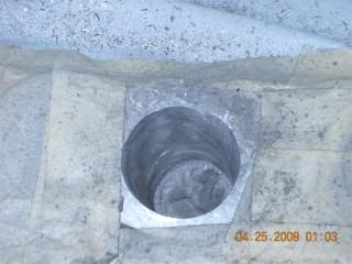
However, to maximize the benefits for porting, there is a sound argument for removing the SPTs and the rods, as well as increasing the length of the taper* (removing that very short "step" immediately under the SPT plate), extending down the length of rhe runner and stopping just short of the valve guide ( ALL of which can be done with the engine in place).
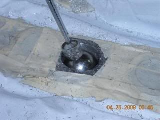
Porting the top-end runners of the heads while motor is in the car...
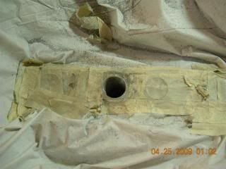
Ball-gauge is used to assure symmetry and uniformity of the cut...
The other requirements include plugging the SPT bearing holes (see Cliff's link) and sealing them, attaining new chip calibration (I have Marc Haibeck's chip) and removing the vacuum line from the (SPT air pressure sensor - attached under the ECM on a 90, or under the plenum on later models. AND, the FULL ENGINE POWER switch has to be (forever) in FULL mode. (The 90s cars achieve this by permanently soldering the leads of the POWER switch together - to assure it always stays "on". The same can be done for the 91+ MY, but too they can have the ECM calibration modified to always be "FULL".)
Personally, I love the "secondary delete" mod. Aside from one very minor annoyance (idle rpm "hunting" with clutch depressed before coming to a stop) or NCRS ranking (almost impossible to tell, unless one knows what to look for), I'll take the immediate snap of WOT throttle response, less/no coking on the secondary input valves, NEVER having a vacuum-related issue with the SPTs, NO "hit" as far as fuel economy goes, parts that don't exist never fail, and they don't cost much! ... What's not to like?
Mechanically speaking, removing the Secondary Port Throttles (SPTs) is very easy to do with engine in the car - as described in the link.
But, as Cliff said, some opt to leave the SPTs in place and simply tie them open - making it easy to revert back to stock later.
However, to maximize the benefits for porting, there is a sound argument for removing the SPTs and the rods, as well as increasing the length of the taper* (removing that very short "step" immediately under the SPT plate), extending down the length of rhe runner and stopping just short of the valve guide ( ALL of which can be done with the engine in place).
Porting the top-end runners of the heads while motor is in the car...


Ball-gauge is used to assure symmetry and uniformity of the cut...

*I subscribe to a maximum of 4% taper - as recommended in several reading sources on porting - to avoid reversion that robs performance. And, for the same reason (reversion), I would remove the SPTs, even if I wasn't increasing the stock size of the runners beyond 36mm (which I did).
The other requirements include plugging the SPT bearing holes (see Cliff's link) and sealing them, attaining new chip calibration (I have Marc Haibeck's chip) and removing the vacuum line from the (SPT air pressure sensor - attached under the ECM on a 90, or under the plenum on later models. AND, the FULL ENGINE POWER switch has to be (forever) in FULL mode. (The 90s cars achieve this by permanently soldering the leads of the POWER switch together - to assure it always stays "on". The same can be done for the 91+ MY, but too they can have the ECM calibration modified to always be "FULL".)
Personally, I love the "secondary delete" mod. Aside from one very minor annoyance (idle rpm "hunting" with clutch depressed before coming to a stop) or NCRS ranking (almost impossible to tell, unless one knows what to look for), I'll take the immediate snap of WOT throttle response, less/no coking on the secondary input valves, NEVER having a vacuum-related issue with the SPTs, NO "hit" as far as fuel economy goes, parts that don't exist never fail, and they don't cost much! ... What's not to like?
Last edited by Paul Workman; 01-13-2017 at 05:07 PM.
01-13-2017, 07:29 PM
#17
Melting Slicks
Thread Starter
Thanks for the info. Having people like you and Dynomite for tech assistance is an incredible resource to have. I will attempt removing the secondaries but likely not port so deep into the heads where the secondaries can no longer be used. You guys helped me when I port matched my 95 heads to my IH's in the car. The primaries only needed it. My plan once the 95 is exempt from emmissions here in GA is to remove the secondaries in that car as well.
I am planning on porting the 92 plenum and IH's plus send the TB to mark to have him install the larger butterflies. I purchased a 36mm gauge ball and all the burrs.
One thing I don't understand is how coolant flows through the throttle body. Both sides are feed from the same source so the there should be no pressure differential accross the TB to induce flow....what am I missing here?
01-13-2017, 10:21 PM
#18
Tech Contributor
..........Let me guess a bit since we really do not know the Coolant Head Loss from the pump through the various engine ports or the Head Loss through the TB. Getting The Air Out of the Coolant System
It appears that the water pump pressure and resulting coolant flow into each cylinder block (right and left) would be close to equal since the coolant flow is separated almost equally on the face of the front cover where the water pump is mounted. The exception here is the length of the coolant path from the water pump impeller is longer on Passenger side which could explain a bit higher coolant pressure on Drivers side to assist TB Coolant Flow from Drivers Side to passenger side. That is a guess.

Now......lets assume the Head Loss for the TB Coolant (the resistance to the flow do to friction/restriction) is lower on the Passenger Side than the Drivers Side. This is because of the length of the hose on Passenger Side from the Injector Housing TB Coolant Port to the Coolant Reservoir is shorter than the length of hose from the Drivers Side TB Coolant hose from Injector Housing TB Coolant Port to the Coolant Reservoir (Drivers Side being more Head Loss because of the longer path).
Now even if you do not assume a bit higher coolant pressure on the Drivers Side Injector Housing as suggested above, with equal Coolant Pressure at the Injector Housings TB Coolant Ports you would have flow out of each Injector Housing TB Coolant Port proportional to the Head Loss the flow sees between the Injector Housings and Coolant Reservoir.
In other words, you would have greater flow out of the Passenger Side Injector Housing TB Coolant Port greater than out of the Drivers Side Injector Housing TB Coolant Port but there would still be flow out of each..........Simply because if there is NO flow out of the Drivers Side TB Coolant Port, there would be NO Head Loss as compared to the Head Loss on the Passenger Side TB Coolant flow up and through the small port in the Injector Housing and the Injector Housing Nipple to which the TB Coolant Hose is attached.
So.......I think with all things being equal on both the Drivers Side and passenger Side Injector Housing Coolant Manifolds (if we want to assume the water pump flow Division is NOT effected by the Dynamics and Flow Paths within the Water Pump) we would still have some flow through the TB given the Coolant Reservoir is relieved of pressure as the Pumps sucks/re-pressurizes Coolant. This assumption assumes we have at least equal or a bit higher Coolant Pressure at the Injector Housings on the Drivers Side. If NOT.......the TB Coolant could be moving from Passenger Side to Drivers Side. What is interesting is the fact the TB Coolant path back to the Coolant Reservoir intersects the Coolant bath from the top of the radiator (the small hose that allows the radiator to vent air on the passenger top side) back to the Coolant Reservoir.
I am guessing here and the Only way to identify what is going on is to take pressures at various places but since I have TB Coolant Blocked.....I do NOT have to Think About it
Another Reason to Block TB Coolant

One more thought since this is philosophy more than engineering because of limited facts.......I have removed several TB Coolant tops and have found a couple totally blocked by scale which I would say....many individuals have already Blocked Throttle Body (TB) Coolant without knowing it

Last edited by Dynomite; 01-13-2017 at 10:50 PM.
01-15-2017, 03:55 PM
#19
Melting Slicks
Thread Starter
Thanks for all the great input. I am deff going to do the port work but still on the fence regarding TB coolant and secondary deleat. I always wanted to keep it mostly stock to retain collector value. Funny thing is I will likely never sell it. Maybe just wire it open. One thing I noticed is the FIC injectors secondary oring locates deeper into the IH bore. So not much can be removed from the injector boss when porting. I am planning on starting a thread documenting my progress. Probably will be looking for an aluminum welder before it is all over.
Last edited by KJL; 01-15-2017 at 03:57 PM.