
Laser alignment of serpentine belts the right way
 11-11-2013, 02:17 AM
#1
Tech Contributor
Thread Starter

Or the best way I know how:
I've been wanting to post this for over a year, but haven't been able to find the time. It took hours to put this together. I hope it helps some of you.
This subject comes up often and causes great frustration with many, so I wanted to post up my thoughts for everyone.
What causes us to lose belts? A quick analysis of the belt can quickly answer what caused a specific belt loss. If it lost ribs then most often, the belt walked due to an alignment issue. Bent and broken tensioners and idlers can also cause a belt to walk off the pulleys.
To determine if belt alignment is the cause of the belt loss, the recommended method is to use the Gates LAZ91006 Serpentine Laser Belt Alignment Tool. This tool can be picked up for around 120.00 shipped.
Here are the types of misalignment, the most common being the second one.

What many don�t know until it�s too late is that these tools do not come calibrated and they are way off. Axial alignment is most common issue I run across. This is where one pulley is farther away from the line that it�s supposed to follow than another. This creates an angle. The angle is determined by the distance the pulleys are from each other versus the distance off axis one is from another. You don�t need to know the angle. You just need to know that one exists and understand that being .0325� off over 6� is double the angle that exists when there is 12� distance between the pulleys. I can�t find the reference, but if I recall correctly, what Gates tells us is that a serpentine belt shouldn�t walk if there is less than � of a rib off over 2 feet. That is � rib over 1 foot and 1/8 rib over 6�. One rib is only .125�, therefore � rib is .0625�. The problem with what Gates provides for calibration is that they provide a ridiculous joke of a piece of paper for calibrating the tool. There are so many ways that it can be off. You�re expected to look through a hole in the feet and fire it on to a line a short distance away. It�s totally flawed and useless. It�s basically a situation where you�re forced to set up the alignment by eye, so I ask �why bother at all?� I believe that using my method you�ll be able to get this laser accurate to .15� over close to 4 feet. That�s 3.75 thousandths for one foot.
To properly calibrate this tool, I use a 4� level and an object that sits square on the counter top surface to use as a target. To adjust the laser, you must unscrew the cap on the end of the laser and it will expose 4 Allen set screws. Those screws should be at clock positions 1, 5, 7, and 11. If they are not, you may loosen the large screws on the side of the tool that affix it to the base and rotate it until you achieve those positions. The tool includes 2 allen wrenches, but I�ve discovered that the included, smaller, metric Allen wrench doesn�t fit and a 5/64� wrench fits it much better.
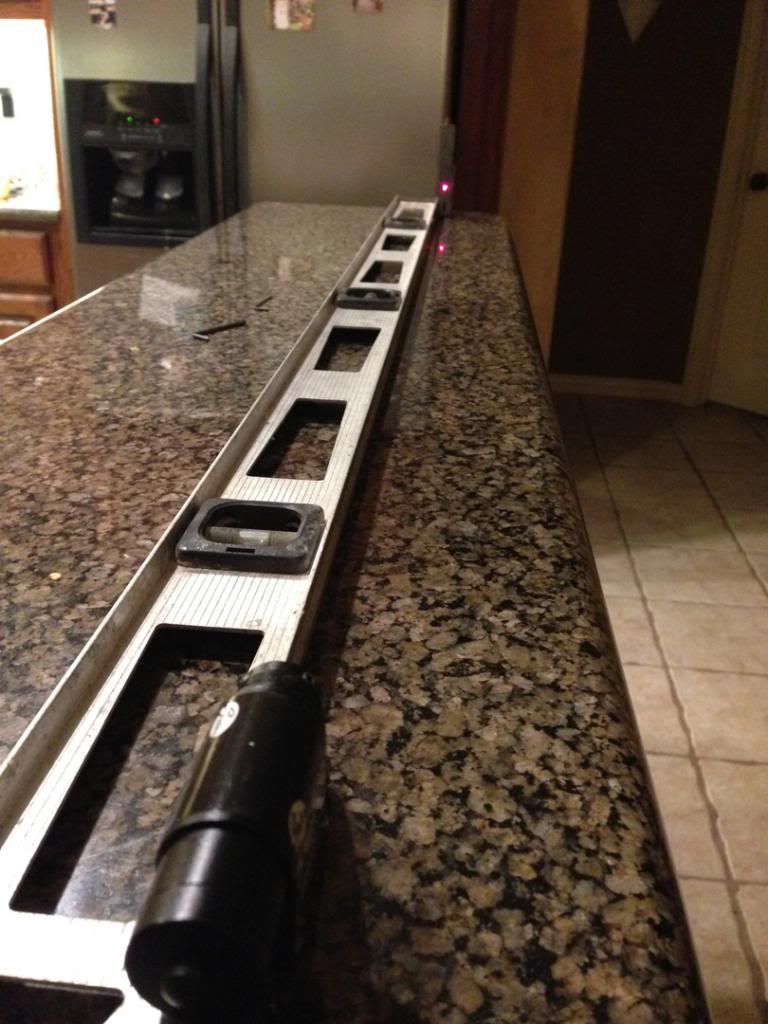
I use a granite surface to perform my alignment. Granite is as true of a surface as you�ll find as long as it doesn�t span across an epoxied joint. I first place the laser at one end of the level with the target as close to the laser as possible, making sure they are both firmly seated against the level. I mark that spot. Then I move the target to the opposite end of the level and determine how far off the laser is. Loosening one screw and tightening the opposite screw is how the laser is adjusted. Although it mainly only matters that the laser is accurate left to right, I like to get it dead on, on the height adjustment too.
To determine if your problem is an axial alignment issue, you have to fire back from the opposite pulley. If you fire from the blower to the crank and it�s off by 1 rib, it should be off by one rib firing from the crank to the blower. If it is not, then you have a pitch problem, meaning your blower bracket is crooked for some reason.
One thing that you must understand is that the crank is your �zero� point. It�s not adjustable, so everything must be adjusted to meet it. Your power steering pulley can be moved in and out, your alternator pulley can be shimmed or you can shave the back side of the ears on the case to move it back, the blower bracket spacers can be shimmed or cut to get the blower in proper alignment. To do this job properly, you must be thorough and patient. This is a tedious job when done properly. To fire from the blower to the crank is not a big deal. I usually only have to remove one spacer on the centrifugals to get enough space to fire the laser to the crank. Firing from the crank to the blower is a different story. You often have to remove everything between the blower and the crank to get a clean shot. Sometimes you can get a really small window to shoot through.
Once you�ve fired your laser, and see a misalignment, many ask �how do I know how much it�s off?� My answer is: remember how wide one rib is. When the pulleys are properly aligned, the laser will hit the peak of one of the ribs. When it does, it will often split the beam into three. Knowing that one rib is .125� and � rib is .625�, I will rock the laser on the pulley and see how much it takes to get to the half rib point and how much it takes to get it to the peak that it should be on. If I barely rock it toward the valley and it hits that valley and then I have to move it a bunch more to get it to the peak, then I know I�m dividing up .0625� and do my best to guess that ratio. A little rock to the valley and double that to get to the peak where I want it means it�s probably .020� to the valley and close to .0425� to the peak. I would adjust by .040� and re-measure. If you discover that the centrifugal blower is too far out you�ll have to cut the spacers. You first need to make sure each and every spacer is equal length using a good dial caliper or micrometer. If they�re not, then that will place your blower bracket at an angle and over a distance will get amplified. The most effective way to shorten the spacers is to use a lathe. If you don�t have a lathe, you can carefully cut them down, but doing it properly is tedious work. I will grind them and when I get close, will start sanding or filing them. I use a dial caliper to measure 3 points to make sure that the spacer end stays �true� or �square�.
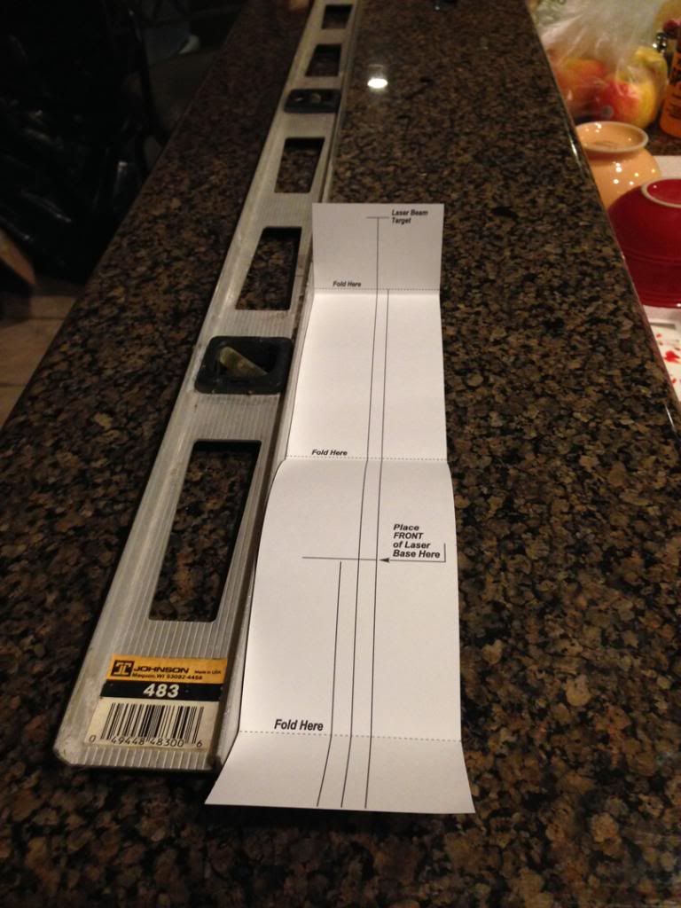
Here�s the ridiculous piece of paper you�re expected to calibrated it with.
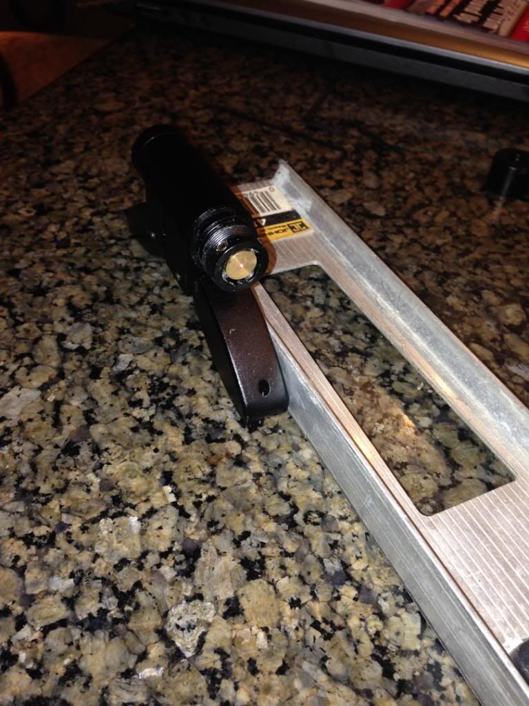
Laser with cap off.
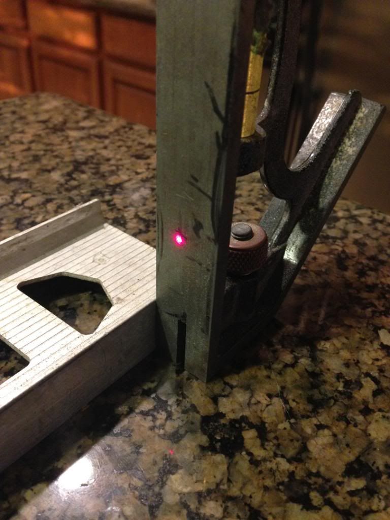
Target close to the laser. That�s where you mark your exact spot that you need to hit.
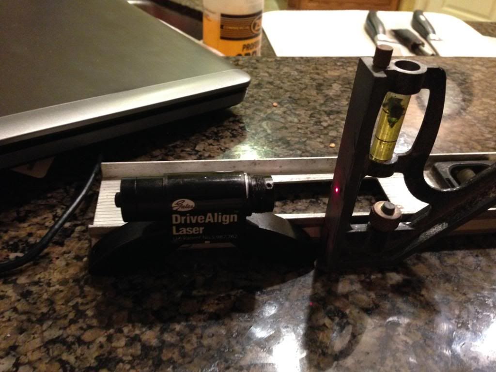
This is after the first adjustment, trying to just get it to hit any part of the target.
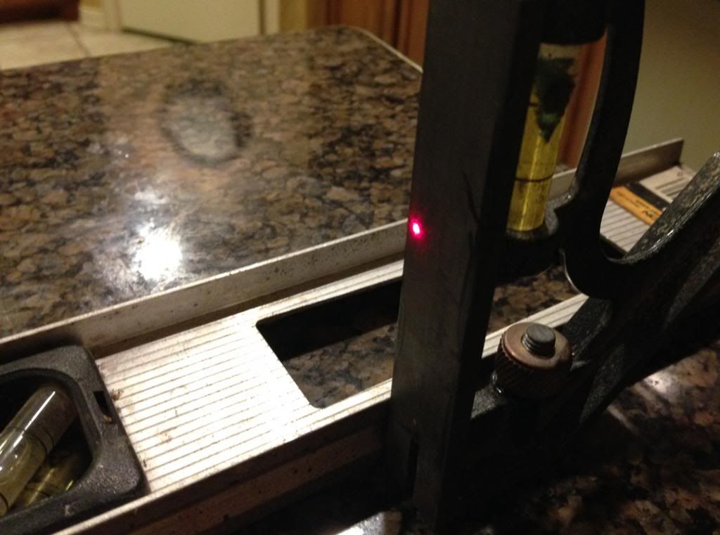
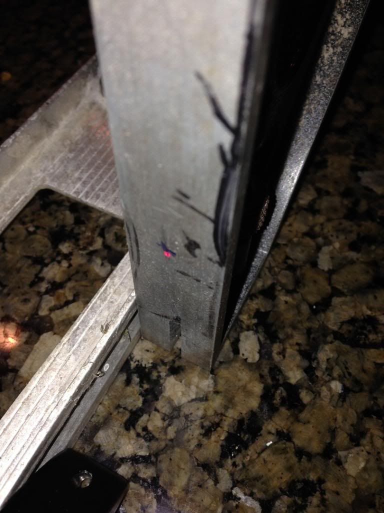
Target at far end
On the money.
Here�s a picture of a A&A kit with one of the spacers removed for laser access.
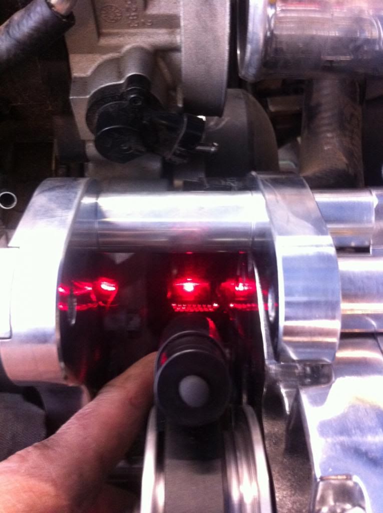
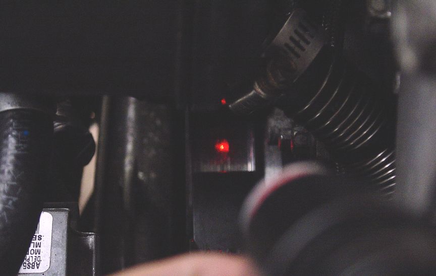
From Alternator to crank
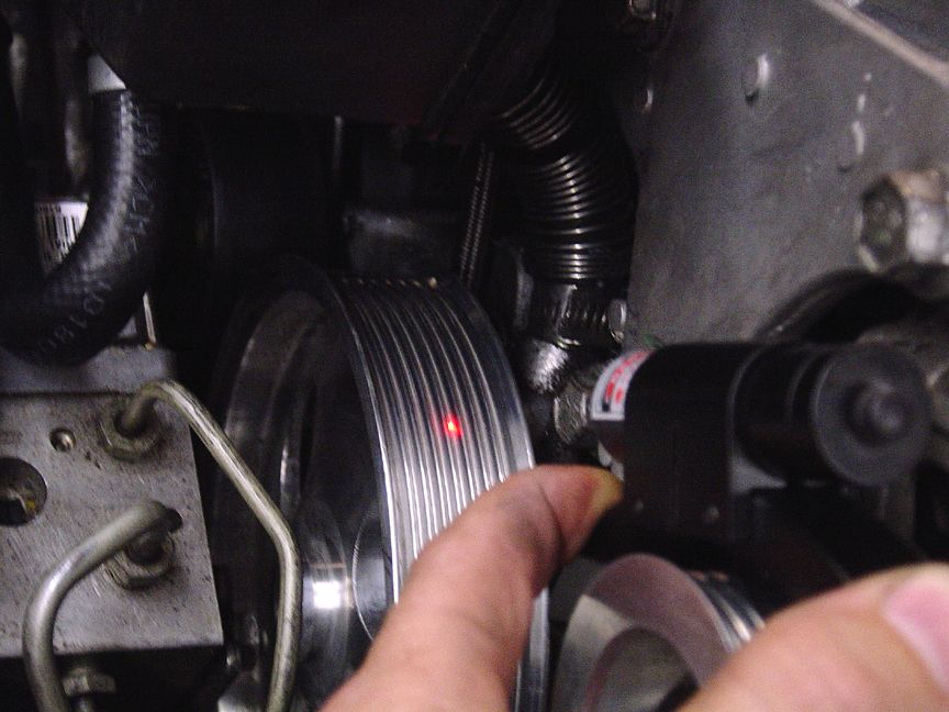
Alternator to power steering pulley.
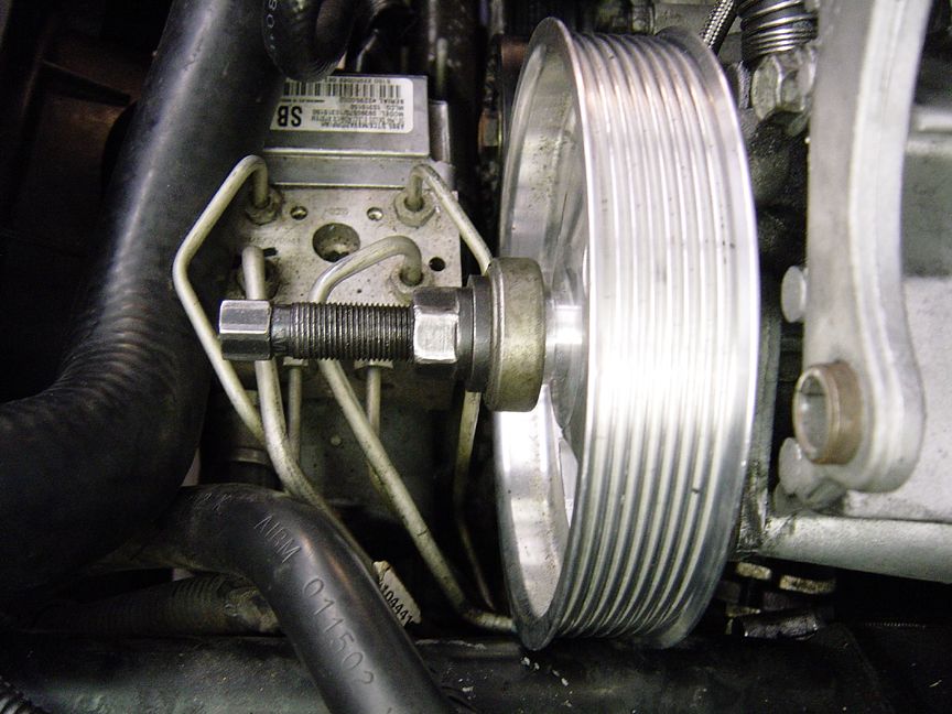
Adjusting power steering to make it right.
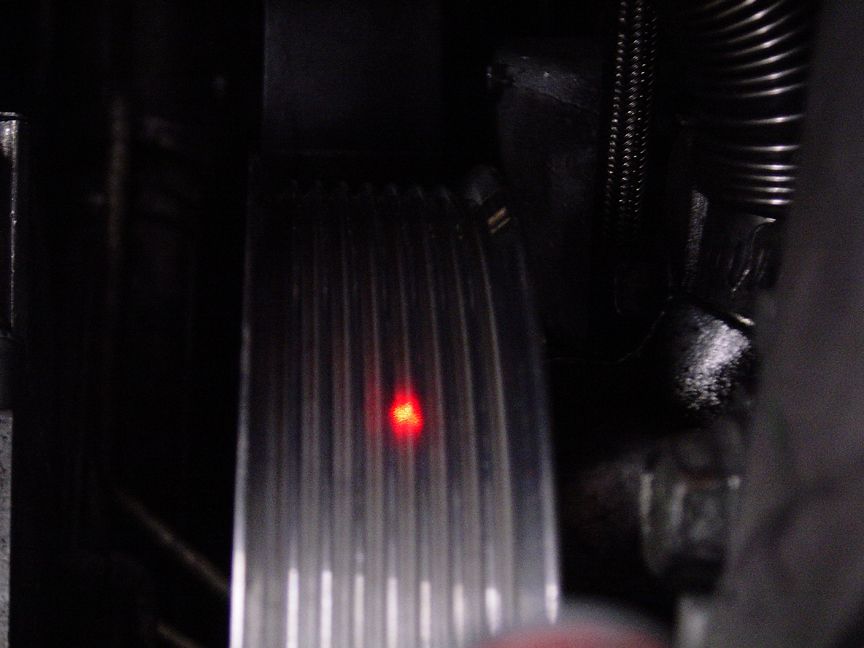
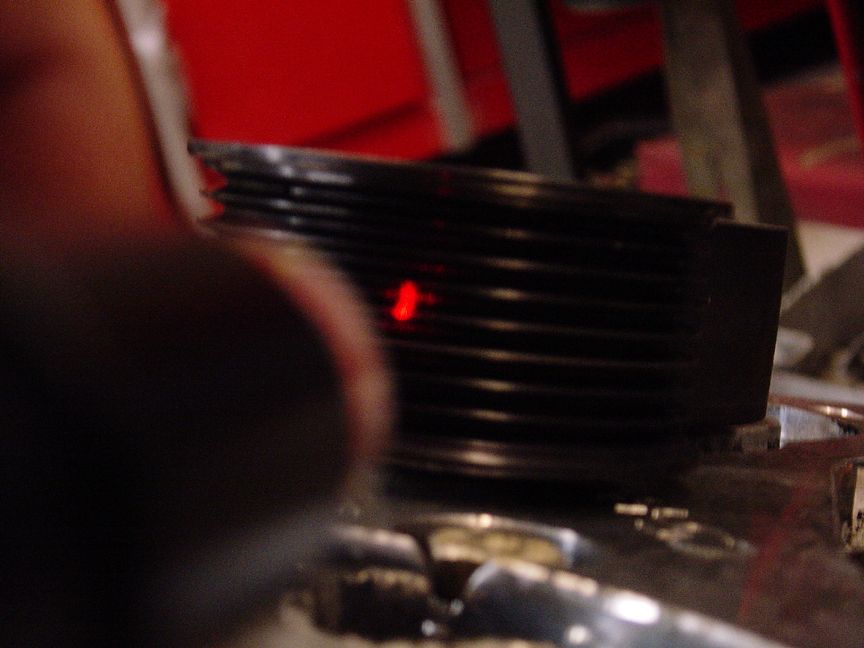
This should be on the peak and it�s in the valley.
I've decided to update this thread with more useful information. I'll go deeper into measurements and solutions.
When you are performing a belt alignment on a centrifugal supercharger assembly, the procedure should include shooting the laser both directions, from the blower to the crank and the crank to the blower. It's important to understand that when shooting each way, if there's a difference between the two, the blower is tilted, PERIOD. This means if you shoot from the blower to the crank and the blower is too far forward by one rib and then shoot from the crank to the blower and it's only forward by 1/2 rib that the blower bracket is tilted. You should always solve the tilt before worrying about adjusting spacer lengths. How you ask? Follow along and I'll give you the answer.
I almost forgot to mention that you should also shoot from the blower to the idler pulley to make sure those are aligned. I've had some people ask me over the years where the laser dot should actually end up. In the peak? The valley? On which rib? The answer is that it should end up on a peak. The same peak that is exposed by the hole, between the feet in the gates tool. When the laser hits it, if it's shiny aluminum, the peak will often split the beam, making a line going left and right. Try rocking your laser tool back and forth until you hit the spot. This should help you gain a clearer idea of what it should look like.
I'll give instructions and pictures for the A&A kit, but all the others work just the same. My recommendation for measuring for a tilt begins with the base bracket. I prefer to drill a small hole across from the top of the flat machined surface of the cylinder head and remove the lower 15mm bolt from the water pump ear. I will use either a depth micrometer or the back end of a dial caliper to get my depth measurements. It's important to hold your measuring device square to the face of the bracket to get the most accurate measurement possible. Before getting the top measurement, make sure that the edge of the hole is de-burred so your tool is able to sit flush on the face of the bracket. I drill a 3/16" hole in the base bracket but you may need to adjust the drill bit size according to the width or diameter of the probe you're using. To determine if there's any base bracket tilt, insert the tool through the lower 15mm (the bolt size is actually a 10mm 1.5 with a 15mm socket head on it) bolt hole and extend the probe to where it touches the cylinder head. Write down that measurement. Then do the same with the upper hole and compare the 2 numbers. If the lower measurement is higher than the upper, it's time to trim the water pump ears. I should mention that this deviation isn't the fault of the supercharger kit manufacturer, rather an issue derived from variances between water pumps. That tolerance isn't so critical to GM or any other manufacturer since having the tensioner off by .040" won't cause an issue. To go about solving this tilt issue, you'll need to true up the ears. If your measurement is off by .020", then you'll need to shave the ears down by that much. "Is it really possible to solve this issue accurately without taking it to a machine shop?", you ask. Yes it is and with relatively basic tools. I have a few tools that I like to use for this. For moving massive amounts of material in a short period of time, I use a large tooth carbide cutting bit. For this more precise work, I like to use sanding discs with either velcro or roloc attachments. I recommend beginning with a heavy grit (such as 35 grit) and as you get close, changing to a finer grit, such as 180 to get the last 5 thousandths off. Once you get the base plate measurements to agree, reinstall the supercharger without the tensioner and shoot it with the laser again. Measurements both directions should agree now. If they don't, start measuring all your spacers, making sure their lengths are all equal. Also make sure that if you're using a bracket that has threads that go all the way through the bracket and the supercharger is behind it, that the bolts aren't long enough to push the supercharger out of alignment.
I've been wanting to post this for over a year, but haven't been able to find the time. It took hours to put this together. I hope it helps some of you.
This subject comes up often and causes great frustration with many, so I wanted to post up my thoughts for everyone.
What causes us to lose belts? A quick analysis of the belt can quickly answer what caused a specific belt loss. If it lost ribs then most often, the belt walked due to an alignment issue. Bent and broken tensioners and idlers can also cause a belt to walk off the pulleys.
To determine if belt alignment is the cause of the belt loss, the recommended method is to use the Gates LAZ91006 Serpentine Laser Belt Alignment Tool. This tool can be picked up for around 120.00 shipped.
Here are the types of misalignment, the most common being the second one.
What many don�t know until it�s too late is that these tools do not come calibrated and they are way off. Axial alignment is most common issue I run across. This is where one pulley is farther away from the line that it�s supposed to follow than another. This creates an angle. The angle is determined by the distance the pulleys are from each other versus the distance off axis one is from another. You don�t need to know the angle. You just need to know that one exists and understand that being .0325� off over 6� is double the angle that exists when there is 12� distance between the pulleys. I can�t find the reference, but if I recall correctly, what Gates tells us is that a serpentine belt shouldn�t walk if there is less than � of a rib off over 2 feet. That is � rib over 1 foot and 1/8 rib over 6�. One rib is only .125�, therefore � rib is .0625�. The problem with what Gates provides for calibration is that they provide a ridiculous joke of a piece of paper for calibrating the tool. There are so many ways that it can be off. You�re expected to look through a hole in the feet and fire it on to a line a short distance away. It�s totally flawed and useless. It�s basically a situation where you�re forced to set up the alignment by eye, so I ask �why bother at all?� I believe that using my method you�ll be able to get this laser accurate to .15� over close to 4 feet. That�s 3.75 thousandths for one foot.
To properly calibrate this tool, I use a 4� level and an object that sits square on the counter top surface to use as a target. To adjust the laser, you must unscrew the cap on the end of the laser and it will expose 4 Allen set screws. Those screws should be at clock positions 1, 5, 7, and 11. If they are not, you may loosen the large screws on the side of the tool that affix it to the base and rotate it until you achieve those positions. The tool includes 2 allen wrenches, but I�ve discovered that the included, smaller, metric Allen wrench doesn�t fit and a 5/64� wrench fits it much better.
I use a granite surface to perform my alignment. Granite is as true of a surface as you�ll find as long as it doesn�t span across an epoxied joint. I first place the laser at one end of the level with the target as close to the laser as possible, making sure they are both firmly seated against the level. I mark that spot. Then I move the target to the opposite end of the level and determine how far off the laser is. Loosening one screw and tightening the opposite screw is how the laser is adjusted. Although it mainly only matters that the laser is accurate left to right, I like to get it dead on, on the height adjustment too.
To determine if your problem is an axial alignment issue, you have to fire back from the opposite pulley. If you fire from the blower to the crank and it�s off by 1 rib, it should be off by one rib firing from the crank to the blower. If it is not, then you have a pitch problem, meaning your blower bracket is crooked for some reason.
One thing that you must understand is that the crank is your �zero� point. It�s not adjustable, so everything must be adjusted to meet it. Your power steering pulley can be moved in and out, your alternator pulley can be shimmed or you can shave the back side of the ears on the case to move it back, the blower bracket spacers can be shimmed or cut to get the blower in proper alignment. To do this job properly, you must be thorough and patient. This is a tedious job when done properly. To fire from the blower to the crank is not a big deal. I usually only have to remove one spacer on the centrifugals to get enough space to fire the laser to the crank. Firing from the crank to the blower is a different story. You often have to remove everything between the blower and the crank to get a clean shot. Sometimes you can get a really small window to shoot through.
Once you�ve fired your laser, and see a misalignment, many ask �how do I know how much it�s off?� My answer is: remember how wide one rib is. When the pulleys are properly aligned, the laser will hit the peak of one of the ribs. When it does, it will often split the beam into three. Knowing that one rib is .125� and � rib is .625�, I will rock the laser on the pulley and see how much it takes to get to the half rib point and how much it takes to get it to the peak that it should be on. If I barely rock it toward the valley and it hits that valley and then I have to move it a bunch more to get it to the peak, then I know I�m dividing up .0625� and do my best to guess that ratio. A little rock to the valley and double that to get to the peak where I want it means it�s probably .020� to the valley and close to .0425� to the peak. I would adjust by .040� and re-measure. If you discover that the centrifugal blower is too far out you�ll have to cut the spacers. You first need to make sure each and every spacer is equal length using a good dial caliper or micrometer. If they�re not, then that will place your blower bracket at an angle and over a distance will get amplified. The most effective way to shorten the spacers is to use a lathe. If you don�t have a lathe, you can carefully cut them down, but doing it properly is tedious work. I will grind them and when I get close, will start sanding or filing them. I use a dial caliper to measure 3 points to make sure that the spacer end stays �true� or �square�.
Here�s the ridiculous piece of paper you�re expected to calibrated it with.
Laser with cap off.
Target close to the laser. That�s where you mark your exact spot that you need to hit.
This is after the first adjustment, trying to just get it to hit any part of the target.
Target at far end
On the money.
Here�s a picture of a A&A kit with one of the spacers removed for laser access.
From Alternator to crank
Alternator to power steering pulley.
Adjusting power steering to make it right.
This should be on the peak and it�s in the valley.
I've decided to update this thread with more useful information. I'll go deeper into measurements and solutions.
When you are performing a belt alignment on a centrifugal supercharger assembly, the procedure should include shooting the laser both directions, from the blower to the crank and the crank to the blower. It's important to understand that when shooting each way, if there's a difference between the two, the blower is tilted, PERIOD. This means if you shoot from the blower to the crank and the blower is too far forward by one rib and then shoot from the crank to the blower and it's only forward by 1/2 rib that the blower bracket is tilted. You should always solve the tilt before worrying about adjusting spacer lengths. How you ask? Follow along and I'll give you the answer.
I almost forgot to mention that you should also shoot from the blower to the idler pulley to make sure those are aligned. I've had some people ask me over the years where the laser dot should actually end up. In the peak? The valley? On which rib? The answer is that it should end up on a peak. The same peak that is exposed by the hole, between the feet in the gates tool. When the laser hits it, if it's shiny aluminum, the peak will often split the beam, making a line going left and right. Try rocking your laser tool back and forth until you hit the spot. This should help you gain a clearer idea of what it should look like.
I'll give instructions and pictures for the A&A kit, but all the others work just the same. My recommendation for measuring for a tilt begins with the base bracket. I prefer to drill a small hole across from the top of the flat machined surface of the cylinder head and remove the lower 15mm bolt from the water pump ear. I will use either a depth micrometer or the back end of a dial caliper to get my depth measurements. It's important to hold your measuring device square to the face of the bracket to get the most accurate measurement possible. Before getting the top measurement, make sure that the edge of the hole is de-burred so your tool is able to sit flush on the face of the bracket. I drill a 3/16" hole in the base bracket but you may need to adjust the drill bit size according to the width or diameter of the probe you're using. To determine if there's any base bracket tilt, insert the tool through the lower 15mm (the bolt size is actually a 10mm 1.5 with a 15mm socket head on it) bolt hole and extend the probe to where it touches the cylinder head. Write down that measurement. Then do the same with the upper hole and compare the 2 numbers. If the lower measurement is higher than the upper, it's time to trim the water pump ears. I should mention that this deviation isn't the fault of the supercharger kit manufacturer, rather an issue derived from variances between water pumps. That tolerance isn't so critical to GM or any other manufacturer since having the tensioner off by .040" won't cause an issue. To go about solving this tilt issue, you'll need to true up the ears. If your measurement is off by .020", then you'll need to shave the ears down by that much. "Is it really possible to solve this issue accurately without taking it to a machine shop?", you ask. Yes it is and with relatively basic tools. I have a few tools that I like to use for this. For moving massive amounts of material in a short period of time, I use a large tooth carbide cutting bit. For this more precise work, I like to use sanding discs with either velcro or roloc attachments. I recommend beginning with a heavy grit (such as 35 grit) and as you get close, changing to a finer grit, such as 180 to get the last 5 thousandths off. Once you get the base plate measurements to agree, reinstall the supercharger without the tensioner and shoot it with the laser again. Measurements both directions should agree now. If they don't, start measuring all your spacers, making sure their lengths are all equal. Also make sure that if you're using a bracket that has threads that go all the way through the bracket and the supercharger is behind it, that the bolts aren't long enough to push the supercharger out of alignment.
Last edited by BLOWNBLUEZ06; 10-17-2016 at 02:23 PM.

The following users liked this post:
CorvetteBrent (05-11-2018)


 11-12-2013, 08:35 AM
#4
Tech Contributor
Thread Starter
Feel free to share your belt alignment stories/nighmares in this thread.
Some things that I've seen cause belt alignment to be off or belt to get thrown:
Water pump gaskets (the old paper ones are a different thickness and will throw off the whole kit.
spacers in the wrong spaces
power steering pulley not installed at the proper depth
overtightened tensioner on Procharger kits
worn out tensioner deflecting when the belt is tightened
loose pulley on the supercharger
supercharger pulley on backwards
Earlier A&A kits had longer spacers and I used to have to cut them down to get them dead on. Here's the spacer lengths that worked for me. It's important to make sure all spacers are equal length.
6-rib 2.280"
8-rib 2.405"
You don't have to cut the spacers down. If you can find the proper ID washers, you can remove the key from the key way, slide the shim on the shaft and reinstall the key and pulley. Breecher 7 made me some custom shims for my blower pulley that included the notch for the key and they worked great!
The following users liked this post:
CorvetteBrent (05-11-2018)
 03-03-2014, 04:43 PM
#6
Team Owner


I received my Gates 91006 this weekend and it was off by more than 3/4" over a 2-foot span so I brought it in to work this morning and used a precision slide on a piece of lab equipment to align it. Using this setup, I got it within about a quarter millimeter over a meter and a half span.
03-14-2014, 05:10 PM
#7
Tech Contributor
Thread Starter
I received my Gates 91006 this weekend and it was off by more than 3/4" over a 2-foot span so I brought it in to work this morning and used a precision slide on a piece of lab equipment to align it. Using this setup, I got it within about a quarter millimeter over a meter and a half span.
03-16-2014, 11:20 AM
#8
Team Owner
It's a precision skivving machine for smoothing out catheters we design and prototype. These catheters are quite small and intended to be inserted in the smaller vessels of the brain neurovasculature to treat aneurysms, stroke and other nasty conditions. That particular piece of equipment is an automated, high-speed unit that cuts excess material off the OD of the catheter after it's been cast and before the final outer jacket is appled. Obviously, extreme accuracy is required when there are only a few thou of wall thickness to work with - thus the precision slide.
The following users liked this post:
CorvetteBrent (05-11-2018)
 03-20-2014, 03:25 PM
#10
ISIS SUCKS FAT CHOAD

I wanted to throw this video fom gates in here.
In the video the technician states that the acceptable Tolerance for pulley misalignment is 1/2 of a rib (0.0625 Zero and six hundred twenty five ten thousandths or 1/16th) for every 6" of pulley separation.
Gates Using The LaserAlignment Tool:
In the video the technician states that the acceptable Tolerance for pulley misalignment is 1/2 of a rib (0.0625 Zero and six hundred twenty five ten thousandths or 1/16th) for every 6" of pulley separation.
Gates Using The LaserAlignment Tool:
Last edited by MVP'S ZO6; 03-20-2014 at 04:53 PM.
The following users liked this post:
CorvetteBrent (05-11-2018)
07-08-2014, 11:03 PM
#11
Drifting

Damn..I calibrated mine with the piece of paper.... actually it came perfect.. always used it like that... i lost the paper though... anyone have a copy they can send????
still... till this day, this tool has saved my day.
still... till this day, this tool has saved my day.

 07-09-2014, 11:19 AM
#13
I would just make my own and use a 4' level. The further you measure/adjust the more accurate it'll be up close
The following users liked this post:
CorvetteBrent (05-11-2018)
01-20-2015, 08:45 PM
#14


awesome thanx im going to need this
03-20-2015, 08:31 PM
#15

Is there anyone who is willing to 'loan' me their laser alignment tool for a fee? i would expect that once the cause of the mis-alignment is found and corrected that it wouldn't re-appear.
I have a 10-rib vortech set-up and i can visibly see the edge of the belt closest to the front of the car wear down while the car is running.
I would send you a shipping label and ship it back to you and give you $20 for the rental of the tool.
Any takers?
I have a 10-rib vortech set-up and i can visibly see the edge of the belt closest to the front of the car wear down while the car is running.
I would send you a shipping label and ship it back to you and give you $20 for the rental of the tool.
Any takers?
03-20-2015, 09:19 PM
#16
Is there anyone who is willing to 'loan' me their laser alignment tool for a fee? i would expect that once the cause of the mis-alignment is found and corrected that it wouldn't re-appear.
I have a 10-rib vortech set-up and i can visibly see the edge of the belt closest to the front of the car wear down while the car is running.
I would send you a shipping label and ship it back to you and give you $20 for the rental of the tool.
Any takers?
I have a 10-rib vortech set-up and i can visibly see the edge of the belt closest to the front of the car wear down while the car is running.
I would send you a shipping label and ship it back to you and give you $20 for the rental of the tool.
Any takers?
Ill pm you in like 20
 03-21-2015, 10:26 AM
#18

