
Rebuilding the Ghost, aka Great White
 10-29-2014, 01:56 PM
#141
Burning Brakes


C5 PCM's can be adjusted for lower or higher levels of knock (noise). But first you'd need to detect knock by yourself. It's well-known how to do it and does not mean just reading spark plugs afterwars. There's also good aftermarket solutions for that (at least in Europe).
 10-29-2014, 08:27 PM
#142
Burning Brakes

Perfect timing, I was going to message you about this. Tired of not having AC already.
Pace figured out the pricing issue on the kit, so it's back to normal again . For anyone wanting this kit, it's actually a Chevrolet Performance Parts a/c add-on kit for the CTS-V LSA's. They use the same a/c belt line as the vettes. Just do a search for GM part number 19299069, and that's it. Compressor is a Denso 10S17F. I have this on mine, and works like a champ while picking up a ton of clearance not just behind but above too
Pace figured out the pricing issue on the kit, so it's back to normal again
. For anyone wanting this kit, it's actually a Chevrolet Performance Parts a/c add-on kit for the CTS-V LSA's. They use the same a/c belt line as the vettes. Just do a search for GM part number 19299069, and that's it. Compressor is a Denso 10S17F. I have this on mine, and works like a champ while picking up a ton of clearance not just behind but above too
10-29-2014, 11:07 PM
#143
Melting Slicks


Thanks for the info. I like the additional safety that a knock sensor can provide when working properly, but at the same time I hope to not push this engine to the edge like the last one. I'll see if they work out and if not I'll have to try other methods.
Any idea how he is developing the timing table for different kpa and rpm values?
Seems like I remember you asking about the a/c lines. I'll have to end up using a different connector on the end of each hose and purchase some fittings to adapt to the a/c compressor. I also had to buy a different pigtail to plug into the a/c kit. The hose won't have to wrap around the motor mount now.
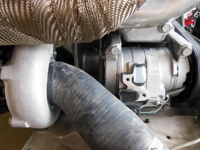
As far as the space between the a/c and turbo compressor inlet, I think it may have opened up an inch or so. It should help some. My main driver for purchasing it was that I needed a new a/c comp and the price for this one was dirt cheap. I'll get a picture for reference on final fitment.
Any idea how he is developing the timing table for different kpa and rpm values?
Seems like I remember you asking about the a/c lines. I'll have to end up using a different connector on the end of each hose and purchase some fittings to adapt to the a/c compressor. I also had to buy a different pigtail to plug into the a/c kit. The hose won't have to wrap around the motor mount now.
As far as the space between the a/c and turbo compressor inlet, I think it may have opened up an inch or so. It should help some. My main driver for purchasing it was that I needed a new a/c comp and the price for this one was dirt cheap. I'll get a picture for reference on final fitment.
as to tune I'm unsure what he does, i just know he uses efi live instead of hp tuners.
10-30-2014, 12:22 AM
#144
Burning Brakes
Which kit did you get from pace?http://paceperformance.com/i-6255556...dd-on-kit.html or
http://paceperformance.com/i-1200472...c-package.html
http://paceperformance.com/i-1200472...c-package.html
11-15-2014, 11:06 AM
#145
Melting Slicks
Thread Starter

Slowly making some progress. There were a couple of little things to check that were easier with the engine out of the car.
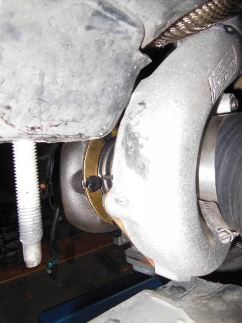
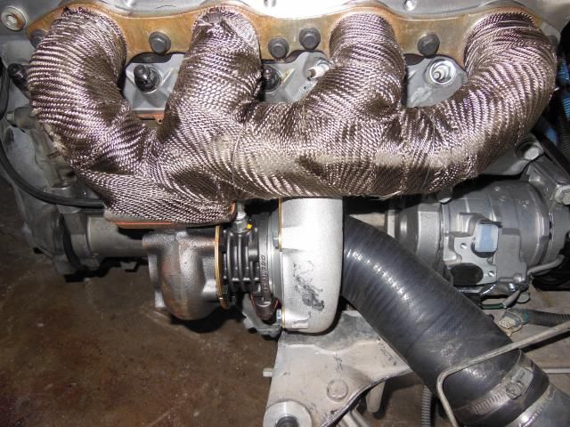
Here is the clearance provided by the a/c compressor in relation to the turbo inlet.
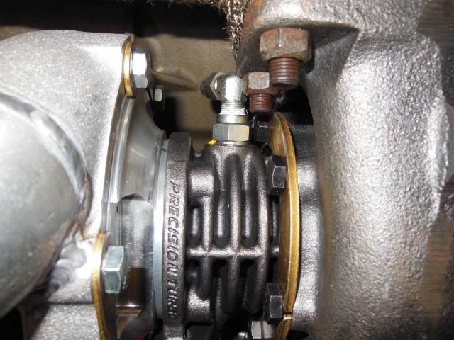
Next, a few people have mentioned that they had issues throwing the a/c belt when using the ati balancer and c6 a/c bracket. Here is a picture showing how the belt doesn't sit as low on the ati pulley (red arrows).
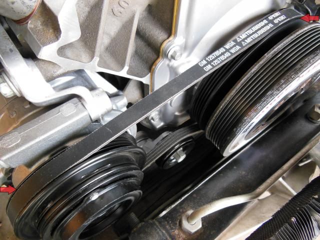
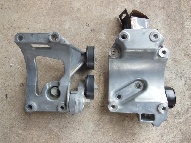
One solution is to use a C5 bracket that has both a fixed idler and tensioner. Unfortunately the new compressor mounts totally different. I'll have to wait and see if there are any issues for now.
Here is the clearance provided by the a/c compressor in relation to the turbo inlet.

Next, a few people have mentioned that they had issues throwing the a/c belt when using the ati balancer and c6 a/c bracket. Here is a picture showing how the belt doesn't sit as low on the ati pulley (red arrows).

One solution is to use a C5 bracket that has both a fixed idler and tensioner. Unfortunately the new compressor mounts totally different. I'll have to wait and see if there are any issues for now.
 11-15-2014, 11:13 AM
#146
Melting Slicks
Thread Starter
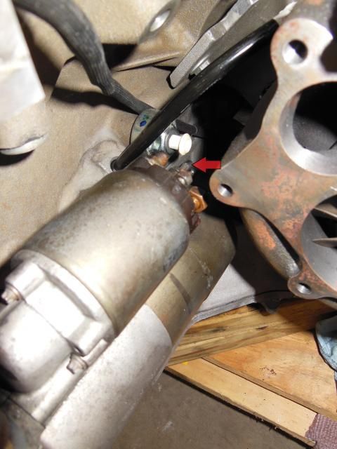
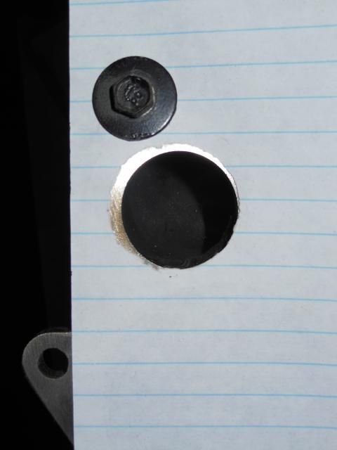
While test fitting the starter, I found a stud on the end that wanted to share the same space as the knock sensor connector. (See red arrow). I ended up just cutting off some of the excess to gain clearance.
Another question was whether or not the feed lines had restrictors in them. I called up TTi and they mentioned that the Precision turbos have their own restrictors. I'm using the original feed lines that were for the Turbonetics turbos. I went ahead and disassembled the lines at the tee and didn't find any in place.
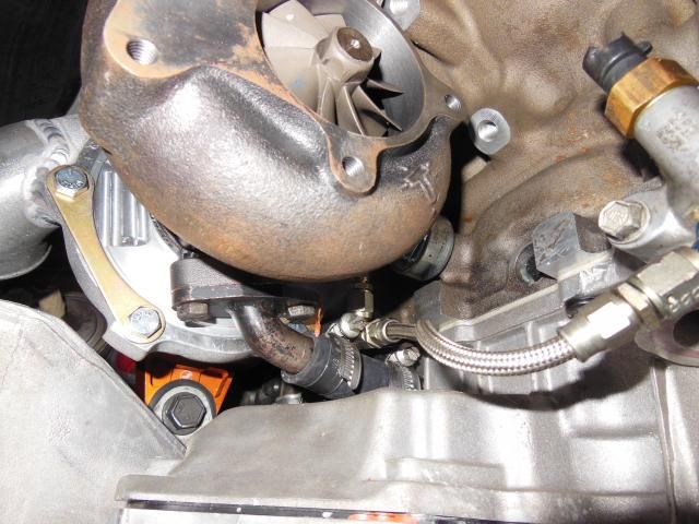
I believe Precision has them located here at the turbo oil feed inlet.
 11-15-2014, 11:22 AM
#147
Melting Slicks
Thread Starter
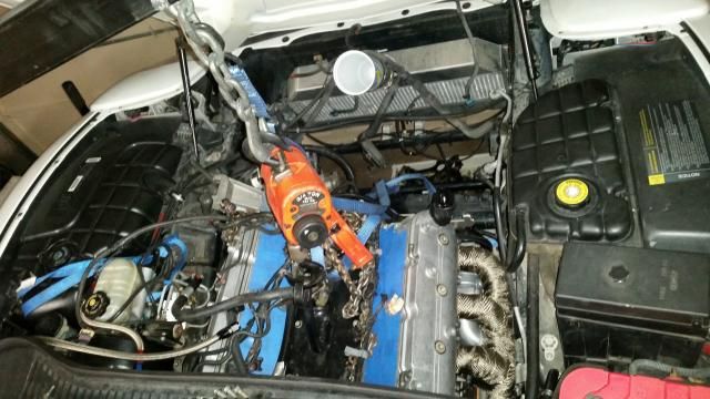
Finally it is time to install the engine. Here is the arrangement. Engine and cradle assembly are on a furniture dolly. The engine hoist is straddling it from the driver's side.
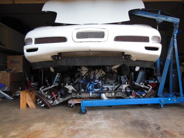
A lift plate (Happy Hooker) is mounted in place of the valley cover. A 3/4 ton chain fall is used in conjunction with the engine lift to hoist everything into place.
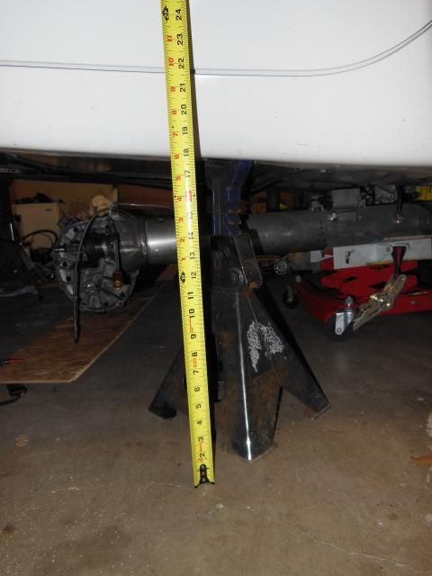
Here are the measurements for the 6 ton jackstands located at the factory lift points on the frame:
Front stand at about 22" high to the frame
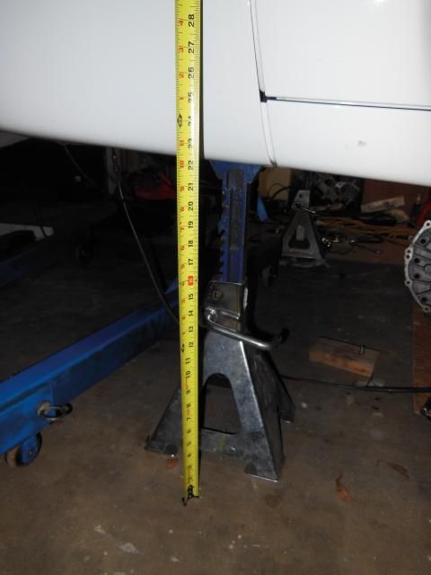
Rear stand at about 18 to 18-1/2" high to the frame

Last edited by Turbo-Geist; 11-15-2014 at 11:30 AM.
11-15-2014, 11:29 AM
#148
Melting Slicks
Thread Starter
Given the theme for this build, it didn't go right in. The new slightly larger turbo hit the frame on the passenger side.
I lowered everything down slid it over to the side and went to work with a 5# hammer. Nothing was stopping this install.
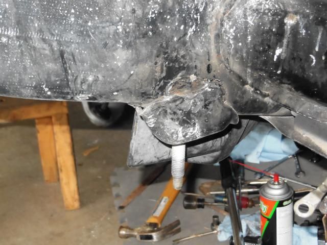
I also took a grinder to one of the bolt bosses on the compressor housing for good measure.

I lowered everything down slid it over to the side and went to work with a 5# hammer. Nothing was stopping this install.

I also took a grinder to one of the bolt bosses on the compressor housing for good measure.


 11-15-2014, 02:31 PM
#151
Drifting

Nice to see some pregress. So are they B covers or E covers? I mean a B is a B so one would think it should fit like the stock ttix turbos. Any plans to mess with the knock sensors much, I keep hearing the gen 3 style don't work great in that external position since they can pick up more noise or different frequencies, etc.
I just missed my opportunity to hit the dyno last weekend It's cold as **** up here now and we are getting snow.
I just missed my opportunity to hit the dyno last weekend
It's cold as **** up here now and we are getting snow.
11-16-2014, 04:25 PM
#152
Melting Slicks
Thread Starter
Nice to see some pregress. So are they B covers or E covers? I mean a B is a B so one would think it should fit like the stock ttix turbos. Any plans to mess with the knock sensors much, I keep hearing the gen 3 style don't work great in that external position since they can pick up more noise or different frequencies, etc.
I just missed my opportunity to hit the dyno last weekend It's cold as **** up here now and we are getting snow.
I just missed my opportunity to hit the dyno last weekend
It's cold as **** up here now and we are getting snow.Good question on the knock sensors. I guess I didn't do enough research in some ways. This is my 1st LS motor swap and it's been more than just a cylinder head change. I'm not well versed in all the little differences. I've read opinions from both groups. There are people saying that it won't work and other people saying that it can be done.
The knock sensors, conservative tuning and meth were a big part of what helped the last combo live for a while. I'll go with what has been stated to work and do some testing. If it doesn't work out, I may have to try something else.
Does anyone have input on the topic?
11-16-2014, 09:52 PM
#153
Drifting
Well they work Ben, but they are not as accurate and really not something to rely on. Just information to look at, but no guarantee's on accuracy. I've seen where some ppl have made the switch to the newer style ones with success. But don't know much about it myself and haven't done any research so that was just by word of mouth. Looking good though mang!
11-17-2014, 10:32 AM
#154
Melting Slicks
Thread Starter
Thanks we'll have to make another pass on I-10 near downtown like we did in the mustang.
Thanks, Jon.
Are you saying the LS1 knock sensors aren't as accurate or any factory knock sensor in this location. I guess we'll have to have one more of many discussions. 
Well they work Ben, but they are not as accurate and really not something to rely on. Just information to look at, but no guarantee's on accuracy. I've seen where some ppl have made the switch to the newer style ones with success. But don't know much about it myself and haven't done any research so that was just by word of mouth. Looking good though mang!
11-17-2014, 10:37 AM
#155
Melting Slicks
Thread Starter
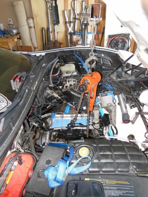
I forgot to post this picture with the engine in place. For anyone using this method, it is important to run a ratchet strap from the chain on the hoist down to the front sway bar. Depending on where you put the lift plate, the engine can have a tendency to be front heavy. This can cause issues with having it hang up on the mounting studs because the front wants to drop before the rear.
 11-17-2014, 02:22 PM
#156
Le Mans Master

I had to pie cut my front cradle mount point and weld it back, similar to how you beat it in with a hammer, LOL. Didn't make sense either especially because my 62's were still Turbonetics and should have the same external dimensions as the 58's. The feed restrictors are indeed in the inlet ot the turbo and Turbonetics adds a screen filter in there too, not sure about the Precisions. I ended up changing to -4 feeds as opposed to -3's because mine are journal bearing and should tecnhically want a bit more oil.
Not sure how well those knock sensors are gonna work. I know Joe's didn't work for **** and had a ton of false knock and he ended up disabling them. And I don't know what would be involved in a swap to the newer two wire sensors like Jeff mentioned.
In any case, just glad to see the motor in this thing.
11-17-2014, 07:05 PM
#157
Melting Slicks
Thread Starter
Thanks, Bill. It feels good to see it back in there and should hopefully give some forward momentum to the project. I've got training for work the next 3 days and then I'll be off till Dec. 1st. Hopefully even more will get done. I'm not sure why these things didn't fit, but I didn't have a welder handy so I took out a few months worth of frustration on the frame. Another dissenting opinion on the LS1 knock sensors. I'm not real ecstatic about it. Do you use your C6 knock sensors, and do they seem accurate? Did Joe make any adjustments on his or just try to plug and play? I'll probably do a comparison tonight between the C5 and C6 knock tables.
In other news...more grinding last night.
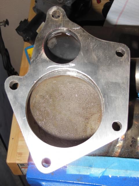
I noticed that the waste gate entry port on the Champion 3" downpipes looked a little small. I took some measurements and compared it to the old DP and it was off. I then made a simple template/tracing off the turbine housing and came up this offset:
The red shows where material needs to be removed and the flange wasn't flush with the i.d. of the pipe. I also smoothed the internal weld some. This had to be done on both DPs.
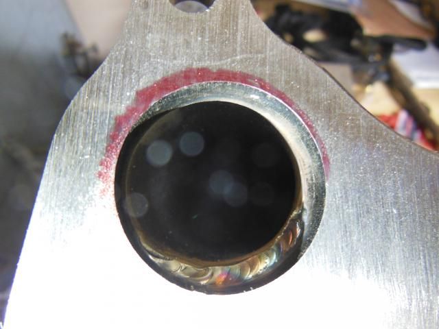
Here is the finished WG port on the DP. I also had to correct a small offset at 11 o'clock to 1 o'clock on the 3" opening of the DP in this picture. The i.d. of the pipe was protruding slightly into the flow path.
In other news...more grinding last night.
I noticed that the waste gate entry port on the Champion 3" downpipes looked a little small. I took some measurements and compared it to the old DP and it was off. I then made a simple template/tracing off the turbine housing and came up this offset:

The red shows where material needs to be removed and the flange wasn't flush with the i.d. of the pipe. I also smoothed the internal weld some. This had to be done on both DPs.

Here is the finished WG port on the DP. I also had to correct a small offset at 11 o'clock to 1 o'clock on the 3" opening of the DP in this picture. The i.d. of the pipe was protruding slightly into the flow path.
 11-17-2014, 10:27 PM
#159
Melting Slicks
Thread Starter
Yes, I am basically port matching this flange on Champion downpipes to the wastegate port on the turbonetics housing. The wg port on the housing was already generously ported by TTi to their specs.
11-17-2014, 11:12 PM
#160
Drifting
Are you saying the LS1 knock sensors aren't as accurate or any factory knock sensor in this location. I guess we'll have to have one more of many discussions.