
ecs instal
 02-08-2015, 12:52 PM
#1
Drifting

Thread Starter

EDIT 30.09.2017: TO VIEW THE OLD PHOTOBUCKET PICTURES DOWNLOAD THE "PHOTOBUCKET EMBED FIX" ADD ONS FOR FIREFOX OR CHROME.
so i unpacked the ecs kit today and thought it to be a good idea to open a thread, as it will be a very basic, with very basic questions, maybe helping other guys.
first of all, if shipping overseas, be shure not to use www.myusa.com, they will screw you.
the ecs kit came with no instructions. are instructions available?
this is it:
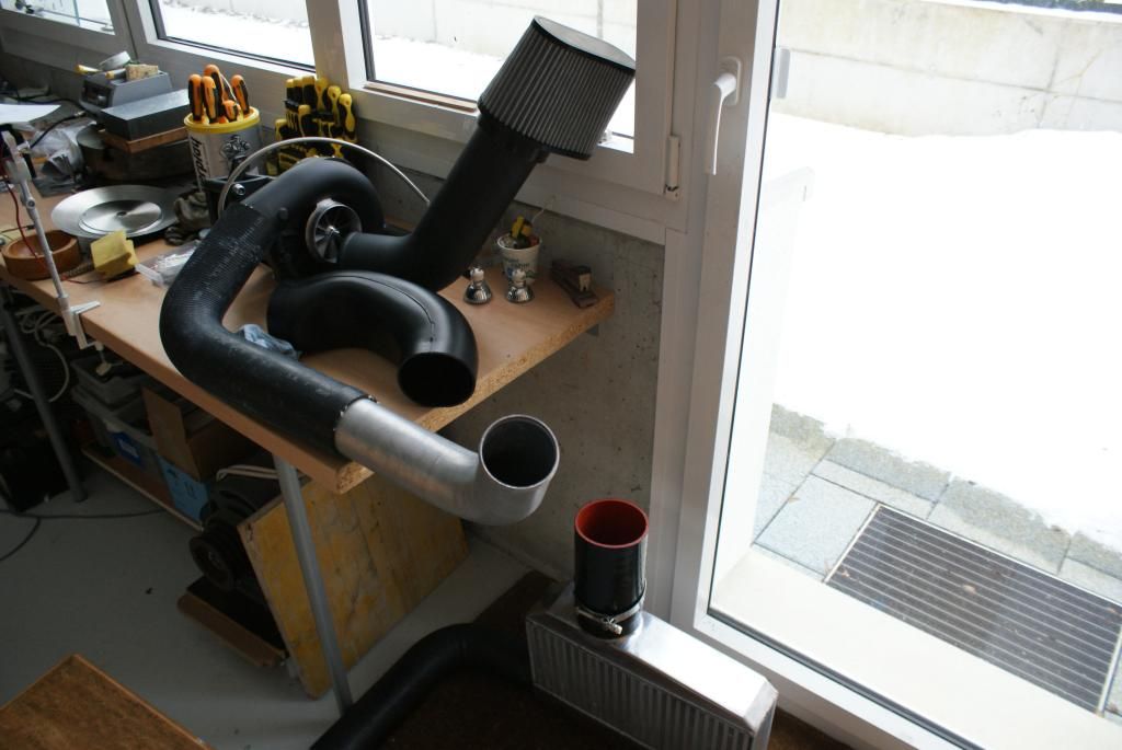
i dont see how the intake pipe will clear the hod, its 35 mm higher than the original "bridge".
i also dont see, how i can connect the maf.
the hose on the discharge side of the head unit is very loose.
what is the braided hose coming from the head unit?
biggest concern, so far, i was convinced the kit came with the boost-a-pump. but no, there is a lingenfelter "high flow pump module" with 10 pages of instruction, on how to instal it. (l710650197.) its a tiny pump and i dont trust it to deliver 600 hp. what is the stock pump rated for? im tempted to get the kenne bell boost-a-pump and/or the racetronix harness instead. any advice on that? how long woud i need to mess with the linenfelter pump for the first time?
also, pinning the crank. how hard is that to do? do you drill between the hard crank and a cast pulley/damper? that would make the dril wander. there is a hardened pin. i have never installed a hardened pin into a drilled hole. you drill undersize, ream and press it in. any thoughts? or is loctite good enough? pinning twice, good idea? why is the supplied drill so long? in view of the limited space and 16 mm lengh of pin?
thats it for now, more question comming up, though.
btw, a 2000 corvette here and the had unit is novi 1500sl.
Last edited by romandian; 09-30-2017 at 01:06 PM.


The following users liked this post:
CorvetteBrent (09-10-2018)
02-08-2015, 05:08 PM
#3
Race Director


Member Since: Dec 2010
Location: Atlanta, GA
Posts: 10,426
Received 1,260 Likes
on
1,055 Posts
2020 Corvette of the Year Finalist (performance mods)
C5 of Year Winner (performance mods) 2019

-the long end of the metal charge pipe goes to your throttle body and the shorter end where it curves goes into the intercooler outlet
-it appears that you have a mafless charge pipe but you have it on wrong... the plastic dongle goes on the blower inlet and your air filter goes on the end of that
-you need to turn the hose around on the blower outlet, the longer end goes on the blower outlet and make sure to tighten it pretty good with the included t-bolt clamps... the shorter end of the aluminum pipe will be on the passenger side of the radiator cradle and the longer end will connect to the rubber discharge pipe
-I'm not familiar with those head units but it is either a drain hose or the oil supply for the head unit
-keep that pump and get a 40a kenne bell bap and racetronix harness, that should be enough to support 600
-there is a fixture that bolts into the balancer to guide the drill bit and the bit is long so you have enough room to reach the snout of the crank through the fixture while giving you enough room to attach it to your drill... you don't need to drill in all the way, just use some masking tape on the bit to measure off enough length needed for the pin to fit in the crank/balancer that way you know when to stop... the bit is the same size as the pin and the pin should just slide in once drilled, you can use some loctite if you wish but it isn't necessary... the crank is tough material to drill so just go a little at a time and spray some wd40 on the bit it if gets too hot and starts smoking
The following users liked this post:
CorvetteBrent (09-10-2018)
02-08-2015, 08:12 PM
#4
Race Director
Member Since: May 2004
Location: Raleigh, NC
Posts: 16,664
Received 1,193 Likes
on
1,052 Posts
St. Jude Donor '15

Instructions are available on their website.... and over in the C6 section you can check out my thread with an install on a C6. Not exactly the same, but may help.
Yeah.. so, the plastic piece that you don't have connected to anything, that is the pipe that has an air filter on one end and connects to the input (center) of the supercharger head unit.
The long black metal pipe goes from the output of the intercooler to the throttle body of the engine. The shorter part connects to the intercooler.
The long 90* "rubber" pipe (for lack of a better word) is backwards I believe (basing that on C6 kit)
Last edited by schpenxel; 02-08-2015 at 08:15 PM.
The following users liked this post:
CorvetteBrent (09-10-2018)
02-08-2015, 08:18 PM
#5
Race Director
Member Since: May 2004
Location: Raleigh, NC
Posts: 16,664
Received 1,193 Likes
on
1,052 Posts
St. Jude Donor '15
also, pinning the crank. how hard is that to do? do you drill between the hard crank and a cast pulley/damper? that would make the dril wander. there is a hardened pin. i have never installed a hardened pin into a drilled hole. you drill undersize, ream and press it in. any thoughts? or is loctite good enough? pinning twice, good idea? why is the supplied drill so long? in view of the limited space and 16 mm lengh of pin?
I can measure the drill bit that came with mine tomorrow and let you know the size. That also should have been included..
The pin will fit snuggly, but not super tight. The balancer bolt will cover up where you drill the hole and make sure it can't go anywhere. No need for loctite or anything like that.
Pinning the crank was a pain to be honest.. but it is necessary. There just isn't much space down there and the steering rack is RIGHT in the way. If you pull the rack you get plenty of room, but pulling it is not much fun.
There is an alternative way of doing it where you loosen the bolts for the front engine cradle.. and loosen the bolts for the engine mounts too. Then you lower the cradle down, and use a jack to lift the engine up. This gets you enough room to pin the crank without removing the steering rack. It is harder to drill the hole doing it this way (less room), but is overall easier than pulling the steering rack in my opinion.
Any other questions, just ask.. I only have experience on the C6 kit, but I would imagine a lot is similar or the same
Last edited by schpenxel; 02-08-2015 at 08:21 PM.
The following users liked this post:
CorvetteBrent (09-10-2018)
 02-09-2015, 08:51 AM
#7
Premium Supporting Vendor
Member Since: Oct 2004
Location: Providing the most proven supercharger kits for your C5/6/7 609-752-0321
Posts: 23,313
Received 1,084 Likes
on
656 Posts
As already stated, very detailed instructions on our web site, feel free to call or email us if you have any questions. I'm not always on here, email is checked 7 days a week. 
The following users liked this post:
CorvetteBrent (09-10-2018)
02-09-2015, 11:02 AM
#8
Drifting
Thread Starter
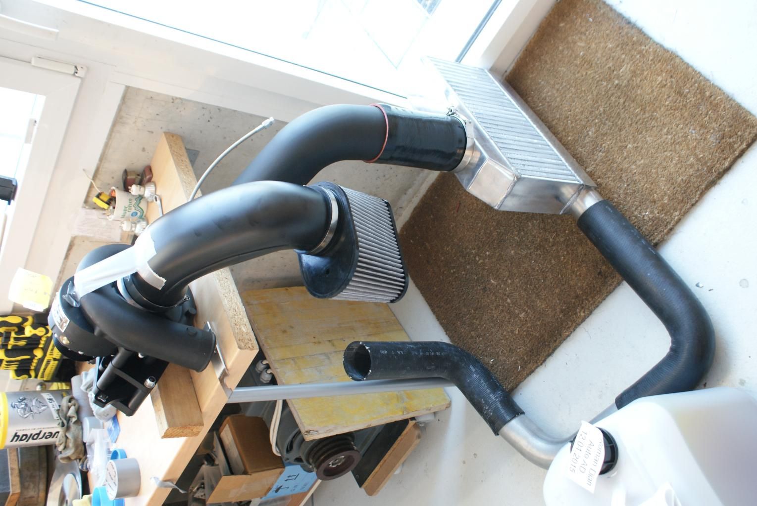
thanks everybody. so is this how its gona work?
[URL=http://s973.photobucket.com/user/romandian/media/2%20034_zpsodbwaifx.jpg.html]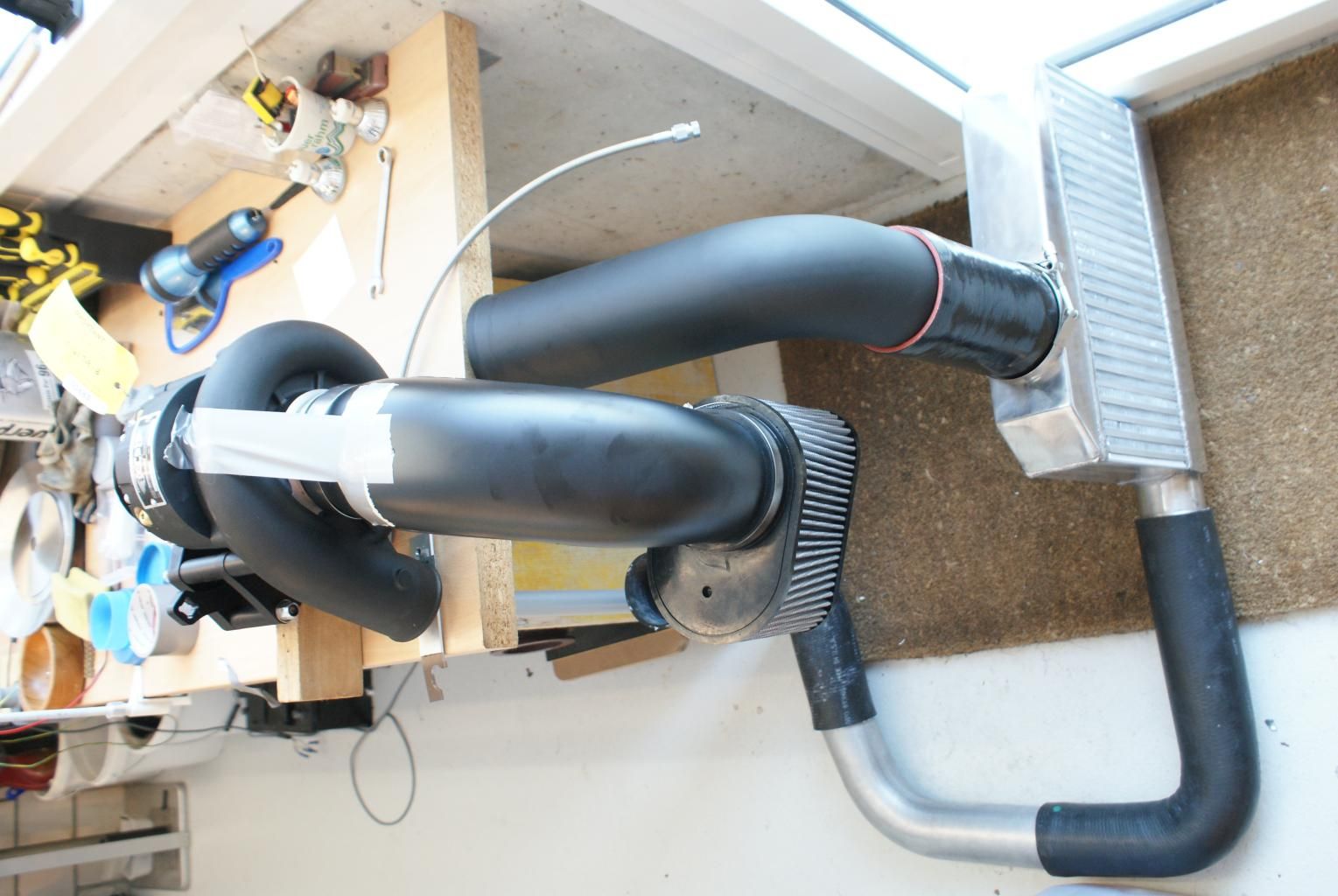 [/URL
[/URL
the compressor outlet pointing straight down? there are ac lines in the way, but i guess i can figure that out.
i found the instructions on their site, but for some reasons the picts dont show, so im still a bit confused. ill either download another browser or aks for a hard copy. why dont they include that in the first place?
also, whats the idea behind that huge pipe from the intercooler tho the maf and throttle body? i will be surprised, if it clears the hood.
i guess i have to get one end of the "bridge" on the compressor inlet somehow (use a hair drier?) and clamp it down.
anyways, i seem to be missing the connection to the throtle body. i asked for a "maf delete kit" without knowing what it was, but expected that as an option. now apparently i cant install the maf at all. (i dont want to blame anybody here, i went through a dealer, so i have to ask him about this and why no boost-a-pump.)
yes, i have the drill guide, but i guess ill make another one and drill 6 mm and get a 1/4" reamer (wont be easy over here). just feel better that way. i will also make a smaller restricror plate for more secure tuning.
i still wonder, what the braided hose is. 1500sl means self lubricating, hopefully.
so anybody knows what the stock pump is good for, with a harness, maybe? as the fuel pressure is not increasing, it might do the job, i suspect. and if not, you adjust the injector table, they are big enough. just thinking aloud here.
also, whats the idea behind the huge pipe from the intercooler to the maf and throtle body? i will be surprised, if it clears the hood.
doug, thanks for chiming in, i will be contacting you soon, as i need some other stuff as well, but i like do discuss things in public, has helped me a lot so far.

[URL=http://s973.photobucket.com/user/romandian/media/2%20034_zpsodbwaifx.jpg.html]
[/URLthe compressor outlet pointing straight down? there are ac lines in the way, but i guess i can figure that out.
i found the instructions on their site, but for some reasons the picts dont show, so im still a bit confused. ill either download another browser or aks for a hard copy. why dont they include that in the first place?
also, whats the idea behind that huge pipe from the intercooler tho the maf and throttle body? i will be surprised, if it clears the hood.
i guess i have to get one end of the "bridge" on the compressor inlet somehow (use a hair drier?) and clamp it down.
anyways, i seem to be missing the connection to the throtle body. i asked for a "maf delete kit" without knowing what it was, but expected that as an option. now apparently i cant install the maf at all. (i dont want to blame anybody here, i went through a dealer, so i have to ask him about this and why no boost-a-pump.)
yes, i have the drill guide, but i guess ill make another one and drill 6 mm and get a 1/4" reamer (wont be easy over here). just feel better that way. i will also make a smaller restricror plate for more secure tuning.
i still wonder, what the braided hose is. 1500sl means self lubricating, hopefully.
so anybody knows what the stock pump is good for, with a harness, maybe? as the fuel pressure is not increasing, it might do the job, i suspect. and if not, you adjust the injector table, they are big enough. just thinking aloud here.
also, whats the idea behind the huge pipe from the intercooler to the maf and throtle body? i will be surprised, if it clears the hood.
doug, thanks for chiming in, i will be contacting you soon, as i need some other stuff as well, but i like do discuss things in public, has helped me a lot so far.
Last edited by romandian; 02-09-2015 at 11:17 AM.
The following users liked this post:
CorvetteBrent (09-10-2018)
02-09-2015, 11:08 AM
#9
Race Director
Member Since: May 2004
Location: Raleigh, NC
Posts: 16,664
Received 1,193 Likes
on
1,052 Posts
St. Jude Donor '15
thanks everybody. so is this how its gona work?
[URL=http://s973.photobucket.com/user/romandian/media/2%20034_zpsodbwaifx.jpg.html][/URL
the compressor outlet pointing straight down? there are ac lines in the way, but i guess i can figure that out.
i found the instructions on their site, but for some reasons the picts dont show, so im still a bit confused. ill either download another browser or aks for a hard copy. why dont they include that in the first place?
i guess i have to get one end of the "bridge" on the compressor inlet somehow (use a hair drier?) and clamp it down.
anyways, i seem to be missing the connection to the throtle body. i asked for a "maf delete kit" without knowing what it was, but expected that as an option. now apparently i cant install the maf at all. (i dont want to blame anybody here, i went through a dealer, so i have to ask him about this and why no boost-a-pump.)
yes, i have the drill guide, but i guess ill make another one and drill 6 mm and get a 1/4" reamer (wont be easy over here). just feel better that way. i will also make a smaller restricror plate for more secure tuning.
i still wonder, what the braided hose is. 1500sl means self lubricating, hopefully.
so anybody knows what the stock pump is good for, with a harness, maybe? as the fuel pressure is not increasing, it might do the job, i suspect. and if not, you adjust the injector table, they are big enough. just thinking aloud here.
[URL=http://s973.photobucket.com/user/romandian/media/2%20034_zpsodbwaifx.jpg.html]
[/URLthe compressor outlet pointing straight down? there are ac lines in the way, but i guess i can figure that out.
i found the instructions on their site, but for some reasons the picts dont show, so im still a bit confused. ill either download another browser or aks for a hard copy. why dont they include that in the first place?
i guess i have to get one end of the "bridge" on the compressor inlet somehow (use a hair drier?) and clamp it down.
anyways, i seem to be missing the connection to the throtle body. i asked for a "maf delete kit" without knowing what it was, but expected that as an option. now apparently i cant install the maf at all. (i dont want to blame anybody here, i went through a dealer, so i have to ask him about this and why no boost-a-pump.)
yes, i have the drill guide, but i guess ill make another one and drill 6 mm and get a 1/4" reamer (wont be easy over here). just feel better that way. i will also make a smaller restricror plate for more secure tuning.
i still wonder, what the braided hose is. 1500sl means self lubricating, hopefully.
so anybody knows what the stock pump is good for, with a harness, maybe? as the fuel pressure is not increasing, it might do the job, i suspect. and if not, you adjust the injector table, they are big enough. just thinking aloud here.
The one thing that looks weird is the silicon coupler from the output of the intercooler. It looks really long. It almost looks like you could cut it in half and use that to connect the other end of the tube to the throttle body. I have no idea if that's right, so hopefully someone else can chime in.
If you download/save the file and then open the instructions in Adobe Reader separately it will probably show up right. I had the same problem when I was trying to look at it in a browser for some reason. Not sure why. I agree, wish they could include a hard copy.
There is no reason to make another drill guide or to use a 1/4" reamer. Up to you, though. What they send works fine. I had to use mine twice and it was still fine (long story, stock balance came apart basically so I had to install a new one)
The hose is an oil drain tube to make oil changes easier. It's just to make it less messy when you change the supercharger oil.
Last edited by schpenxel; 02-09-2015 at 11:12 AM.
The following users liked this post:
CorvetteBrent (09-10-2018)
02-09-2015, 11:24 AM
#11
Race Director
Member Since: May 2004
Location: Raleigh, NC
Posts: 16,664
Received 1,193 Likes
on
1,052 Posts
St. Jude Donor '15
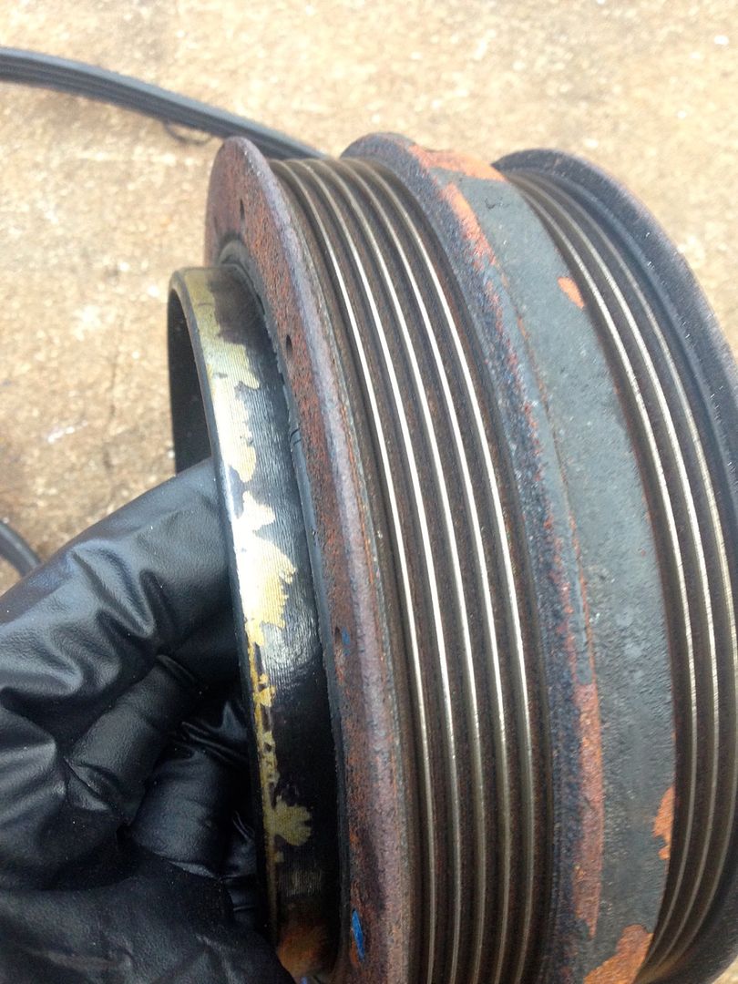
Yep. Not a fault of the SC kit.. the balancers are just not that great from the factory.
I installed a ~$200 one from Summit Racing to replace it
I put a picture below. I was fortunately still idling in the driveway when it happened.. it had start rubbing on the timing cover, but thankfully I turned it off before there was any real damage
I installed a ~$200 one from Summit Racing to replace it
I put a picture below. I was fortunately still idling in the driveway when it happened.. it had start rubbing on the timing cover, but thankfully I turned it off before there was any real damage
02-09-2015, 11:59 AM
#12
Premium Supporting Vendor
Member Since: Oct 2004
Location: Providing the most proven supercharger kits for your C5/6/7 609-752-0321
Posts: 23,313
Received 1,084 Likes
on
656 Posts
Sorry to hear you guys would have preferred hard copies on the instructions, we are going to start asking the DIY's if they would prefer that from now on. Thanks for the suggestion.
The following users liked this post:
CorvetteBrent (09-10-2018)
02-09-2015, 12:01 PM
#13
Race Director
Member Since: May 2004
Location: Raleigh, NC
Posts: 16,664
Received 1,193 Likes
on
1,052 Posts
St. Jude Donor '15
A quick parts list would be great too, more so the DIY guys can inventory everything before getting deep into the install and realizing something small is missing
The following users liked this post:
CorvetteBrent (09-10-2018)
02-09-2015, 12:05 PM
#14
Premium Supporting Vendor
Member Since: Oct 2004
Location: Providing the most proven supercharger kits for your C5/6/7 609-752-0321
Posts: 23,313
Received 1,084 Likes
on
656 Posts

A packing list, maintenance schedule and return policy paperwork is included with each kit.
The following users liked this post:
CorvetteBrent (09-10-2018)
02-09-2015, 12:29 PM
#15
Race Director
Member Since: May 2004
Location: Raleigh, NC
Posts: 16,664
Received 1,193 Likes
on
1,052 Posts
St. Jude Donor '15
02-10-2015, 10:18 AM
#16
Drifting
Thread Starter
an exploded view of the system would definitely be helpful. it took me quite a bit of time, to figure out, the compressor discharge was going straight down.
what might this be:
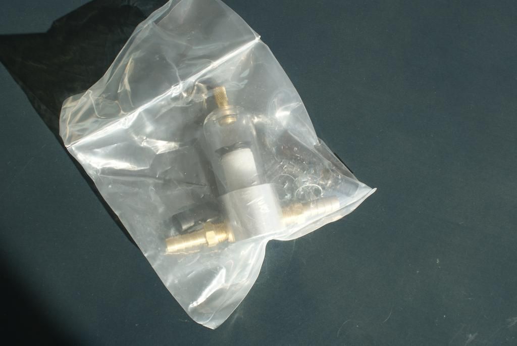
well, i understand, it the oil catch can. i have also figured out, that the big washer is the restrictor plate and goes into the neck of the air filter. it apparently is retained by the three screws horizontally. (i dont like that.)
but it took me a couple of hours looking on pictures in the other threads to figure in out.
well, biggest problem: they tell you to crack off the idler pulley bracket. thats bad. it seems to be part of the block casting. i will have to deinstall the system every other year for inspection purposes. is there a way to use the new idler with the stock belt?
The following users liked this post:
CorvetteBrent (09-10-2018)
02-10-2015, 10:40 AM
#17
Premium Supporting Vendor
Member Since: Oct 2004
Location: Providing the most proven supercharger kits for your C5/6/7 609-752-0321
Posts: 23,313
Received 1,084 Likes
on
656 Posts
All of this is very detailed in the instructions, including clocking the blower. Please read them before proceeding!!
02-10-2015, 10:51 AM
#18
Drifting
The one thing that looks weird is the silicon coupler from the output of the intercooler. It looks really long. It almost looks like you could cut it in half and use that to connect the other end of the tube to the throttle body. I have no idea if that's right, so hopefully someone else can chime in.
The following users liked this post:
CorvetteBrent (09-10-2018)
02-10-2015, 11:03 AM
#19
Drifting
Thread Starter
doug, i only found this:
http://www.eastcoastsupercharging.co...harger-kit.pdf
is there anything else? maybe im missing something. clocking?
http://www.eastcoastsupercharging.co...harger-kit.pdf
is there anything else? maybe im missing something. clocking?
Last edited by romandian; 02-10-2015 at 11:05 AM.
02-10-2015, 11:06 AM
#20
Race Director
Member Since: May 2004
Location: Raleigh, NC
Posts: 16,664
Received 1,193 Likes
on
1,052 Posts
St. Jude Donor '15
The following users liked this post:
CorvetteBrent (09-10-2018)