Proper crankcase evacuation for Turbo and Centri builds
 10-15-2015, 12:05 PM
#1
Melting Slicks

Thread Starter


For those that want to maintain proper crankcase evacuation at all times, and retain a emissions compliant PCV system, here is how the ELite Engineering and the Colorado Speed systems accomplish this.
This will allow your engine to live a nice long life, will always pull suction on the crankcase (unlike venting where pressure is allowed to first build and then vent causing piston ring instability, etc.) and remove the oil from your intake air-charge preventing the oil caused detonation/Knock Retard resulting in timing pulled and less power.
Turbo or centri super charger installation as follows:
Anytime you have a forced induction application where the intake manifold is pressurized by boost, the installation of a air/oil*separation*system*is unique as you must ensure boost does not find it's way into the crankcase, and as intake manifold vacuum is only available during idle, light cruise and deceleration, a secondary suction source to maintain evacuation is critical.
These applications should be installed as follows:
The center of the main separation unit will connect to either the rear of the drivers side valve cover (GM LS based, on others the "dirty", or "foul" side) or the valley cover on GM LS based engines. The valve cover and valley barb can be "T'd" together as well, and this will connect to the center fitting with no checkvalve inline.
One outlet, with checkvalve flowing away from the can will run to the intake manifold vacuum barb. (GM LS this is on the passenger side of the IM snout, LT GDI it is on the drivers side of the snout). This provides evacuation suction when in non-boost operation.
The second outlet with checkvalve flowing away from the can will run to the inlet of the head unit, generally into the flexible coupler that attaches the turbo to the main intake pipe running to the air filter. You MUST have this barb installed as close to the inlet (cold side) as possible to realize as much suction possible as every inch toward the main air filter this suction drops substantially, and at boost you need it the most to maintain evacuation and prevent any pressure building. Some chose to drill and tap directly into the hosing, just ensure you are not touching the turbine blade or damage will occur.*
Now we move to the cleanside. This will be the opposite valve cover as the dirty side, and with the GM LS you will replace the oil fill cap with the cleanside separator. Then remove the line that connects to the inner front pf the passenger side valve cover (new LT DI v8's this is at the front of both valve covers and the oil fill cap is on the drivers side, you connect both valve covers with a 1/2" ID hose and the cleanside incoming air enters the CSS that replaced the oil fill cap). *Cap the valve cover, and run a hose (no checkvalve) to the very end, or base of the main airfilter where you install a barb.
(*For a twin turbo, T both turbo inlets together for the secondary outlet from the can (I will resend with that edited in). *During boost when needed the most, this is when you need the added suction of both turbo inlets.
The E2-X Ultra is recommended for all twin turbo applications due to the added capacity and most effective separation.)
This will maintain a closed, emissions compliant system, will provide crankcase evacuation at all times, boost or no boost, and will prevent crankcase pressure from building and always provide proper evacuation and "flushing".
 10-16-2015, 12:17 PM
#4
Melting Slicks
Thread Starter
Hi All,
A twin screw like the Eaton based brands, etc. do not pressurize the intake manifold as the lower plenum serves as this, so you will always have suction available to maintain proper evacuation, but adding the second suction source just in front of the throttle body will give you that added evacuation capacity when needed the most, and that is when running hard/WOT.
So, inlet of air/oil separator will be attached in most cases to the rear of the drivers side valve cover, one outlet with checkvalve flowing away from separator (these are available from ColoradoSpeed direct, high quality billet check valves for under $20)
The second outlet from the separator (ColoradoSPeed Dualvalve Monster or the ELite E2-X or Ultra) to a barb you install in the coupler that attaches the CAI tube t the throttle body.
On the cleanside, or passenger side valve cover on a LS based engine, you will replace the oil fill cap with the Billet cleanside unit:
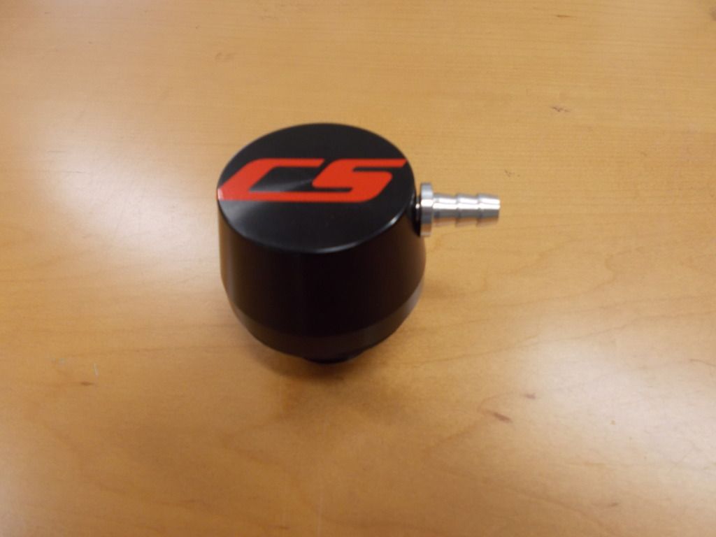
and the line form the TB will connect to the barb on the CSS. Cap the inner barbs then on the pass side valve cover.
I'll try to get some diagrams for you in the next few days, but if not clear now, just ask.
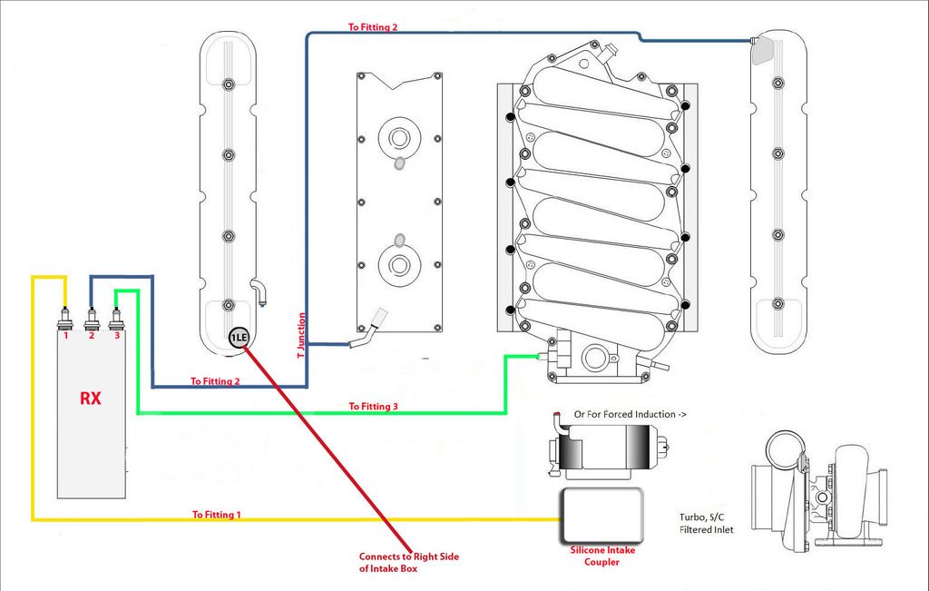
For NA, Centri or turbo, here is a diagram I found online that shows the correct touting, but does not show the inline checkvalves (and this can be used for twin screw as well following the written instructions):
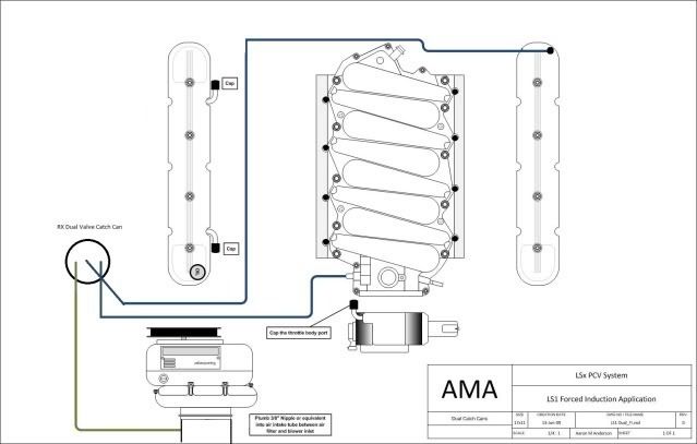
And a better one for Centri or turbo:
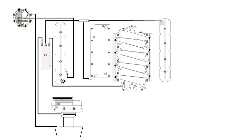
And dry sump:
I'll try and make my own with the checkvalves inline and not integrated like these show.
A twin screw like the Eaton based brands, etc. do not pressurize the intake manifold as the lower plenum serves as this, so you will always have suction available to maintain proper evacuation, but adding the second suction source just in front of the throttle body will give you that added evacuation capacity when needed the most, and that is when running hard/WOT.
So, inlet of air/oil separator will be attached in most cases to the rear of the drivers side valve cover, one outlet with checkvalve flowing away from separator (these are available from ColoradoSpeed direct, high quality billet check valves for under $20)
The second outlet from the separator (ColoradoSPeed Dualvalve Monster or the ELite E2-X or Ultra) to a barb you install in the coupler that attaches the CAI tube t the throttle body.
On the cleanside, or passenger side valve cover on a LS based engine, you will replace the oil fill cap with the Billet cleanside unit:

and the line form the TB will connect to the barb on the CSS. Cap the inner barbs then on the pass side valve cover.
I'll try to get some diagrams for you in the next few days, but if not clear now, just ask.
For NA, Centri or turbo, here is a diagram I found online that shows the correct touting, but does not show the inline checkvalves (and this can be used for twin screw as well following the written instructions):

And a better one for Centri or turbo:

And dry sump:

I'll try and make my own with the checkvalves inline and not integrated like these show.
Last edited by COSPEED; 10-16-2015 at 12:23 PM.
10-16-2015, 12:30 PM
#5
Pro


This is great, thanks!
I was running a MM can w dirty side connnected to oil fill port, and clean side to air filter element. However during boost it would pressurize crankcase.
I am planning on keeping the one dirty side on oil fill, and add another dirty to driver side rear valve cover port, and keep clean side in air filter element.
Does this sound reasonable? Added a pic where you could see old configuration.
10-16-2015, 01:07 PM
#6
Melting Slicks
Thread Starter
The issue with a can like that is it allows crankcase pressure to build until the breather valve opens and vents, so that is never good. Doing a dual outlet like these I mention (they are also 95-98% effective vs most 15-50%) and always pull evacuation suction on the crankcase preventing this. This helps maintain piston ring stability.
You can still use the oil fill cap as long as it is running to the base of your main air filter, but it has no coalescing media in it to prevent oil ingestion into your air filter. If you remove your air tube from the SC inlet, you should see oil residue showing it getting in via that oil cap. And you want zero oil ingestion, especially with FI as this causes Knock and less power is released per combustion. If it is just a hose going down to the bottom of the engine compartment, then it will draw unfiltered air and dust/dirt/sand/water directly into that passenger side of the engine. If it has a small filter on it then that prevents the dirt. but water will still be drawn in in the rain.
If it also connects to the MM can, then you have effectively defeated ALL crankcase evacuation and are retaining almost all the damaging contaminants from the combustion by-products (water, unburnt fuel, abrasive soot and carbon particles, sulfuric acid etc) and life of the engine is greatly reduced.
The PCV system does far more than help meet emissions. It also performs several critical functions to remove the compounds that will destroy an engine over time, and to defeat those is a guaranteed way to incur rapid engine wear.
The Billet CSS I pictured has stainless steel coalescing media in it to to trap the oil any time there may be a "burp" of pressure when transitioning between boost and non boost operation, and that is then pulled right back into the valve cover.
Great questions!! And the pics really help.
Last edited by COSPEED; 10-16-2015 at 01:10 PM.
10-16-2015, 01:30 PM
#7
Racer


Member Since: Mar 2015
Location: Greenville South Carolina
Posts: 280
Likes: 0
Received 3 Likes
on
3 Posts
Currently I have everything you mentioned except on my oil fill I just have a breather filter, I guess I will run a line from there to my throttle body instead. Very helpful thank you!
Or I'm still lost, a diagram for twin screw would be amazing.
Or I'm still lost, a diagram for twin screw would be amazing.
Last edited by wildthingwood1994; 10-16-2015 at 01:34 PM.
10-16-2015, 01:38 PM
#8
Pro
Originally Posted by coSPEED2
The issue with a can like that is it allows crankcase pressure to build until the breather valve opens and vents, so that is never good. Doing a dual outlet like these I mention (they are also 95-98% effective vs most 15-50%) and always pull evacuation suction on the crankcase preventing this. This helps maintain piston ring stability.
You can still use the oil fill cap as long as it is running to the base of your main air filter, but it has no coalescing media in it to prevent oil ingestion into your air filter. If you remove your air tube from the SC inlet, you should see oil residue showing it getting in via that oil cap. And you want zero oil ingestion, especially with FI as this causes Knock and less power is released per combustion. If it is just a hose going down to the bottom of the engine compartment, then it will draw unfiltered air and dust/dirt/sand/water directly into that passenger side of the engine. If it has a small filter on it then that prevents the dirt. but water will still be drawn in in the rain.
If it also connects to the MM can, then you have effectively defeated ALL crankcase evacuation and are retaining almost all the damaging contaminants from the combustion by-products (water, unburnt fuel, abrasive soot and carbon particles, sulfuric acid etc) and life of the engine is greatly reduced.
The PCV system does far more than help meet emissions. It also performs several critical functions to remove the compounds that will destroy an engine over time, and to defeat those is a guaranteed way to incur rapid engine wear.
The Billet CSS I pictured has stainless steel coalescing media in it to to trap the oil any time there may be a "burp" of pressure when transitioning between boost and non boost operation, and that is then pulled right back into the valve cover.
Great questions!! And the pics really help.
You can still use the oil fill cap as long as it is running to the base of your main air filter, but it has no coalescing media in it to prevent oil ingestion into your air filter. If you remove your air tube from the SC inlet, you should see oil residue showing it getting in via that oil cap. And you want zero oil ingestion, especially with FI as this causes Knock and less power is released per combustion. If it is just a hose going down to the bottom of the engine compartment, then it will draw unfiltered air and dust/dirt/sand/water directly into that passenger side of the engine. If it has a small filter on it then that prevents the dirt. but water will still be drawn in in the rain.
If it also connects to the MM can, then you have effectively defeated ALL crankcase evacuation and are retaining almost all the damaging contaminants from the combustion by-products (water, unburnt fuel, abrasive soot and carbon particles, sulfuric acid etc) and life of the engine is greatly reduced.
The PCV system does far more than help meet emissions. It also performs several critical functions to remove the compounds that will destroy an engine over time, and to defeat those is a guaranteed way to incur rapid engine wear.
The Billet CSS I pictured has stainless steel coalescing media in it to to trap the oil any time there may be a "burp" of pressure when transitioning between boost and non boost operation, and that is then pulled right back into the valve cover.
Great questions!! And the pics really help.
I think you are saying to get the billet cap and follow your 'AMA' diagram for routing like you have posted?
Sorry for the redundant questions!
10-16-2015, 03:28 PM
#9
Melting Slicks
Thread Starter
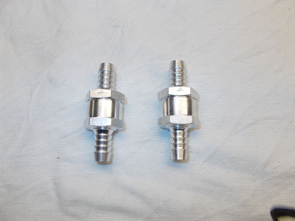
The Elite and ColoradoSpeed systems come with these high quality billet checkvalves and are resistant to all oil and fuel and withstand 30 # boost.
http://www.coloradospeed.com/oil-pum...8-p-28561.html
http://www.coloradospeed.com/?main_p...ha_filter_id=0

http://www.coloradospeed.com/oil-pum...8-p-28561.html
http://www.coloradospeed.com/?main_p...ha_filter_id=0
10-16-2015, 03:32 PM
#10
Melting Slicks
Thread Starter
Yes except the oil cap. That replaces with the Cospeed cleanside unit or the MM will work, and it needs to run to your main air filter. Ask all the questions you have. These are so misunderstood.
10-16-2015, 10:51 PM
#11
Thanks so much for posting this up.. this should be a sticky!
Could you explain why on the centri diagram you posted you don't recommend using the passenger side valve cover fitting? Not even T'ing into the driver side fitting?
Could you explain why on the centri diagram you posted you don't recommend using the passenger side valve cover fitting? Not even T'ing into the driver side fitting?
10-17-2015, 11:57 AM
#12
Running Guns & Moonshine


From the diagram: "A better one for centri or turbo"
Ok, that makes sense to me.
Where would the line for the CSS go in this case?
Ok, that makes sense to me.
Where would the line for the CSS go in this case?
10-17-2015, 12:54 PM
#13
Melting Slicks
Thread Starter
On a Centri application, the intake manifold and the CAI tube are pressurized when in boost, so it would run from the CSS to the main air filter. You want the incoming cleanside air filtered, and never subject to boost pressure that can enter the crankcase.
You must always maintain a clear and complete separation of the "clean" and "dirty" sides so that the damaging compounds that enter the crankcase as blow-by are always flushed, and evacuated (sucked out) before they can settle and accumulate mixing with the oil, and the sulfuric acid collecting on the internal metal parts attacking them. All of these are in a suspended state when they enter, but if not removed (evacuated) by flushing and suction, they quickly drop and mix with the engine oil, and that is why it is so critical to never defeat these functions of the PCV system. Anyone running a defeating system take an oil sample next drain and send it off for analysis to see just how high the concentrates that wear your engine out are, and Blackstone charges extra do give acid and other contents so use their "better" service or there are a few others that do so automatically. You want an analysis showing all particulates, acid, soot, carbon as well as the metals and fuel percentages.
The most common thoughts pertaining to the crankcase are oil ingestion and pressure, but evacuation and flushing as well as continuous suction removing these compounds are just as, if not more important to engine longevity.
If you look back at the pre-PCV systems of the early 60's and before, engines rarely went more than 40-50k miles before needing rebuilds, (and oil formulas, better materials, and more exact manufacturing have all contributed to longevity over time) but engine life unexpectedly doubled and tripled in the years following Federally mandated PCV system as an unanticipated benefit from a purely emissions mandated system. It was not until years later that engineers and scientist discovered the PCV system greatly increased engine life and decreased wear as the PCV system was removing, or evacuating these damaging compounds before they could settle and mix with the engine oil.
Prior to this the engines had no actual evacuation, they had "road draft" tubes that left a line of oil down the center of each lane on the roads, and allowed dirt/dust/etc to also enter the crankcase through reversion. Mixed with the damaging combustion by-products, this was what was wearing the engines out so quickly in those days. I remember my Grandfather changing oil every 1500 miles when I was a kid in the 60's. (And he poured the drain oil in the dirt/gravel driveway to keep dust down! Just as the city did on the dirt roads then, and we road our bikes in the DDT sprayers behind the mosquito fogger trucks!!) SO much has changed, so to go back to what is essentially the old road draft Venting is sacrificing your engine and more.
Keep these good questions coming. My goal is for all to understand all that is involved with proper crankcase evacuation and long engine life.

Jason
10-17-2015, 01:05 PM
#14
Melting Slicks
Thread Starter
The best is to evacuate the foul, or dirty vapors from the drivers side using the passenger side for clean air entering giving a good cross-flow flushing. If using the valley, then Ting both valve covers together allows clean air to enter both, travel along the rocker arms, down the push-rod valleys, and up into the valley baffle with the foul or dirty vapors.
Be aware though, the valley baffles in some cases were not properly seated or sealed in the manufacturing process and in those cases, oil can be sucked up by the windage spray, and also on the LS3/L99 and similar truck engines from 2008 to 2013 can also have a "mis-aligned" baffle underneath that can suck oil directly in. If you have a catchcan that fills up in say 100 miles or so, either of these are usually to blame and there are TSB's out on both of these issues. You can also T the valley and drivers side for the dirty side evacuation and use just the passenger side for cleanside as well. Just think of your engine as a room full of smoke with a grate pushing smoke in constantly (the blow-by all engines have) and each valve cover as a window. If you open only one, some smoke will exit, but the room will never clear. Open the opposite window and put a fan in it sucking out, and the room clears right away and stays clear. Your crankcase is the "smoke filled room", and the smoke is the contaminates entering at all times.
Hope that makes it easier to visualize.
 10-17-2015, 01:33 PM
#15
Pro
Originally Posted by coSPEED2
The issue with a can like that is it allows crankcase pressure to build until the breather valve opens and vents, so that is never good. Doing a dual outlet like these I mention (they are also 95-98% effective vs most 15-50%) and always pull evacuation suction on the crankcase preventing this. This helps maintain piston ring stability.
You can still use the oil fill cap as long as it is running to the base of your main air filter, but it has no coalescing media in it to prevent oil ingestion into your air filter. If you remove your air tube from the SC inlet, you should see oil residue showing it getting in via that oil cap. And you want zero oil ingestion, especially with FI as this causes Knock and less power is released per combustion. If it is just a hose going down to the bottom of the engine compartment, then it will draw unfiltered air and dust/dirt/sand/water directly into that passenger side of the engine. If it has a small filter on it then that prevents the dirt. but water will still be drawn in in the rain.
If it also connects to the MM can, then you have effectively defeated ALL crankcase evacuation and are retaining almost all the damaging contaminants from the combustion by-products (water, unburnt fuel, abrasive soot and carbon particles, sulfuric acid etc) and life of the engine is greatly reduced.
The PCV system does far more than help meet emissions. It also performs several critical functions to remove the compounds that will destroy an engine over time, and to defeat those is a guaranteed way to incur rapid engine wear.
The Billet CSS I pictured has stainless steel coalescing media in it to to trap the oil any time there may be a "burp" of pressure when transitioning between boost and non boost operation, and that is then pulled right back into the valve cover.
Great questions!! And the pics really help.
You can still use the oil fill cap as long as it is running to the base of your main air filter, but it has no coalescing media in it to prevent oil ingestion into your air filter. If you remove your air tube from the SC inlet, you should see oil residue showing it getting in via that oil cap. And you want zero oil ingestion, especially with FI as this causes Knock and less power is released per combustion. If it is just a hose going down to the bottom of the engine compartment, then it will draw unfiltered air and dust/dirt/sand/water directly into that passenger side of the engine. If it has a small filter on it then that prevents the dirt. but water will still be drawn in in the rain.
If it also connects to the MM can, then you have effectively defeated ALL crankcase evacuation and are retaining almost all the damaging contaminants from the combustion by-products (water, unburnt fuel, abrasive soot and carbon particles, sulfuric acid etc) and life of the engine is greatly reduced.
The PCV system does far more than help meet emissions. It also performs several critical functions to remove the compounds that will destroy an engine over time, and to defeat those is a guaranteed way to incur rapid engine wear.
The Billet CSS I pictured has stainless steel coalescing media in it to to trap the oil any time there may be a "burp" of pressure when transitioning between boost and non boost operation, and that is then pulled right back into the valve cover.
Great questions!! And the pics really help.

I can assemble a motor, but I can't for my life picture this setup in my head!
 10-17-2015, 01:39 PM
#16
Melting Slicks
Thread Starter
Since I am still confused and my motor and pcv is out it the car, I'm going to lay out all the parts on the floor and take a picture of what I think the correct routing is, and the from there on maybe I can figure this out
I can assemble a motor, but I can't for my life picture this setup in my head!
I can assemble a motor, but I can't for my life picture this setup in my head!
Your not alone. Let me know on any part and I'll do my best to guide you. The PCV system and proper crankcase evacuation is probably the most misunderstood by laymen and today's tuner shops alike, not to mention the dealer techs as no where is this taught except in the professional racing World, and that is generally type and class specific.
There are still some good knowledgeable "Old Timer senior techs" at some dealers yet that understand, but they are getting more scarce by the year.
 10-17-2015, 11:55 PM
#18
Pro

for roots type blower
I run the conventional pvc routing with a catch can, and have plumbed another route to the air cleaner with a check valve to hold the vacuum until the crankcase sees pressure. When the Crankcase is under pressure the vacuum is overwhelmed by the blow-by, another pvc connected to the valve cover will then released through another catch can to the air cleaner. So we now have positive ventilation valved for or vacuum to the manifold side of the valve body and valve for pressure to the intake side with both going through a separate catch cans.
I hope this explains the process Ive used for 3 years, oil stays remarkably clean I don't add oil between changes.
10-18-2015, 12:19 AM
#19
Racer
Member Since: Mar 2015
Location: Greenville South Carolina
Posts: 280
Likes: 0
Received 3 Likes
on
3 Posts
for roots type blower
I run the conventional pvc routing with a catch can, and have plumbed another route to the air cleaner with a check valve to hold the vacuum until the crankcase sees pressure. When the Crankcase is under pressure the vacuum is overwhelmed by the blow-by, another pvc connected to the valve cover will then released through another catch can to the air cleaner. So we now have positive ventilation valved for or vacuum to the manifold side of the valve body and valve for pressure to the intake side with both going through a separate catch cans.
I hope this explains the process Ive used for 3 years, oil stays remarkably clean I don't add oil between changes.
I run the conventional pvc routing with a catch can, and have plumbed another route to the air cleaner with a check valve to hold the vacuum until the crankcase sees pressure. When the Crankcase is under pressure the vacuum is overwhelmed by the blow-by, another pvc connected to the valve cover will then released through another catch can to the air cleaner. So we now have positive ventilation valved for or vacuum to the manifold side of the valve body and valve for pressure to the intake side with both going through a separate catch cans.
I hope this explains the process Ive used for 3 years, oil stays remarkably clean I don't add oil between changes.

