
c5 stereo wiring diagram?


 01-09-2010, 07:39 PM
#4
Melting Slicks

Thread Starter

all i need to know is the color of the accessory wire on the stock harness. i am fixing a problem that the car audio shop did. they made my deck only come on when full power is on and i would like for it to be just acc
01-09-2010, 08:31 PM
#5
Drifting


See if this site helps, at the bottom of the page looks to be a color code. Hope this helps...........
http://www.installer.com/cars/by_car.php?carid=1084
http://www.installer.com/cars/by_car.php?carid=1084

The following users liked this post:
ChrisLSx (02-07-2018)
01-10-2010, 01:56 AM
#8
Tech Contributor
Member Since: Dec 2003
Location: Horncastle Lincolnshire, England
Posts: 19,384
Likes: 0
Received 79 Likes
on
61 Posts
2023 C5 of the Year Finalist - Unmodified

Pentavolvo knows his stuff
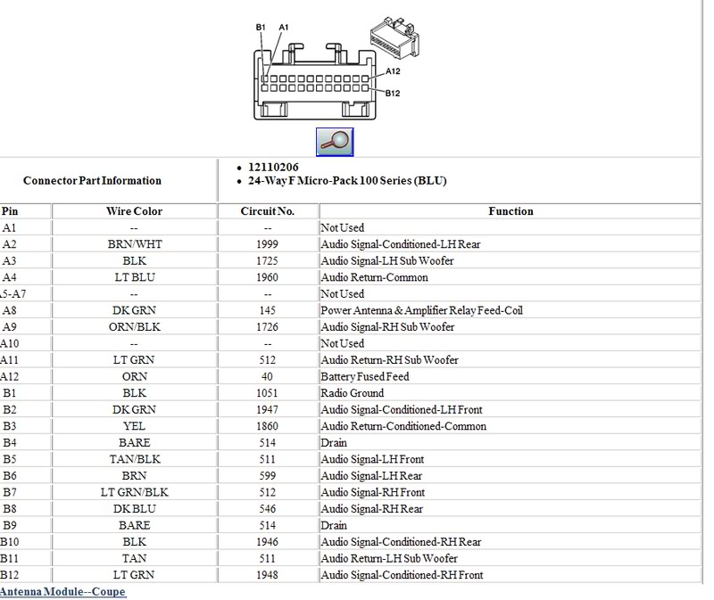
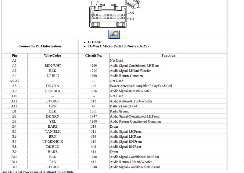
Heres the wiring diagram so you can see what connections you do have. 3 outputs to the CD Changer called remote radio outputs.
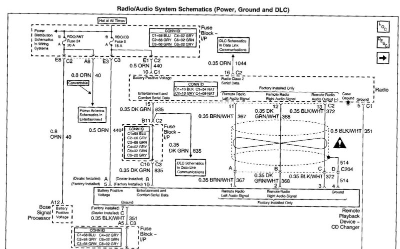
Heres the wiring diagram so you can see what connections you do have. 3 outputs to the CD Changer called remote radio outputs.
01-10-2010, 03:07 AM
#9
Melting Slicks
Thread Starter
so why is there no accessory. i am trying to re hook my head unit so that it will turn on with acc rather than on. would you guys happen to know what color wire the acc is on the main ignition?
 01-12-2010, 04:43 AM
#12
Tech Contributor
Member Since: Dec 2003
Location: Horncastle Lincolnshire, England
Posts: 19,384
Likes: 0
Received 79 Likes
on
61 Posts
2023 C5 of the Year Finalist - Unmodified
The brown wire works. I found that it was a tad busy in there and sometimes I'd get a power interrupt. Just a bad connection on my part I guess.
Here are other options for ACC power
The easiest is to use fuse #22 which is live but not used for any other function. I used an “add a circuit” connector to hook in. This gives you the switched hot.
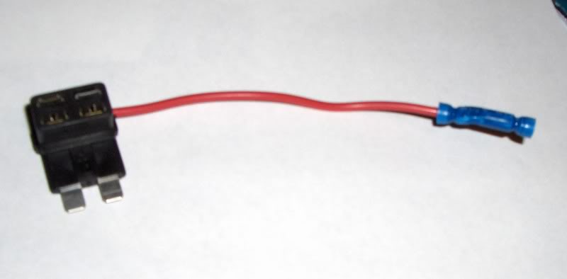
These are not my pics but show you the hook ups
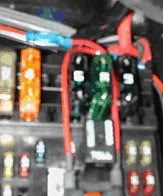
You can see how the connectors slot into the fuse box/
The other option is to hook up into the spare connector which is available for ancillary devices. I believe this is used for the CD changer so it may not be an option for you if you have one of those fitted.
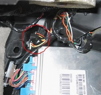
In the passenger footwell (unless you have a 2004) behind the kick board you’ll see a fuse block and to its left a silver box which is the BCM. There are three wires taped together feeding into a connector.
The Black wire is ground; the Orange wire is powered through fuse #7 but is permanent hot. The Yellow wire is powered through fuse #11 and is switched hot when the key is in the ACC or ON positions. Hook up to the Yellow for switched ACC.
Here are other options for ACC power
The easiest is to use fuse #22 which is live but not used for any other function. I used an “add a circuit” connector to hook in. This gives you the switched hot.
These are not my pics but show you the hook ups
You can see how the connectors slot into the fuse box/
The other option is to hook up into the spare connector which is available for ancillary devices. I believe this is used for the CD changer so it may not be an option for you if you have one of those fitted.
In the passenger footwell (unless you have a 2004) behind the kick board you’ll see a fuse block and to its left a silver box which is the BCM. There are three wires taped together feeding into a connector.
The Black wire is ground; the Orange wire is powered through fuse #7 but is permanent hot. The Yellow wire is powered through fuse #11 and is switched hot when the key is in the ACC or ON positions. Hook up to the Yellow for switched ACC.
 01-14-2010, 12:42 AM
#18
Le Mans Master
