
Any tips on replacing the steering wheel position sensor?

 09-16-2007, 07:05 PM
#22
Le Mans Master


Member Since: Sep 2000
Location: Clouds Over California
Posts: 6,856
Received 438 Likes
on
235 Posts

 09-17-2007, 07:08 AM
#23
Drifting


Yes nice write up, I anticipate having to do this soon. So I have subscribed to this thread and will report back how it goes as well. I have an 01 and am getting an intermittent Service Active Handling, Traction Control with ABS light......codes are constantly 1287,88.
09-17-2007, 07:57 PM
#24
Burning Brakes

Thread Starter

Member Since: Feb 2001
Location: Milwaukee & Long Beach WI & CA
Posts: 793
Likes: 0
Received 2 Likes
on
1 Post
Also, if you have a column lock bypass you might want to remove it so that the column is locked when you replace the sensor to avoid any possibilty of the wheel getting turned around while handling the steering column.
09-19-2007, 07:19 AM
#25
Drifting
What fuse needs to be pulled for the airbag?
09-23-2007, 10:37 AM
#26
Drifting
Well, I replaced the steering sensor yesterday and took the car for a test drive. The ever-present "service active handling" message did not appear this time. I'll call the swap a successful fix!
I followed the instructions in this thread by Mathia (thanks!) and they were right-on. Here are some info I'll contribute:
1. Before doing anything, I un-installed my column lock bypass to allow the wheel to lock in position when I wanted it to. After testing the column lock, I proceded with Mathia's steps.
2. To get at the steering shaft nut (you can't turn the bolt head, sorry Mathia), you'll need a swivel socket and about 10" of extension. You can get at the nut from the topside or from the side...I removed the black plastic wheel well cover behind the LF wheel (in front of the side cove) and you can easily see the target nut. You don't have to remove the wheel to accomplish this. This was a discovery because the steering bolt dropped down and I could not find it so I had to go searching and removed the wheel well cover and found the bolt.
3. The fuse to pull that disables the airbag is #16 in the fuse box in the passenger foot well.
4. To get at the steering column components inside, you have to remove the interior panel below the steering wheel. This is described elsewhere for installing the column lock bypass among other things. Just search the forum and you'll find the directions in many places.
5. When removing the metal knee bolster (has white foam on it), you also have to remove the horizontal black plastic panel that has the footwell light. It has typical interior panel push-on fasteners and one metal ring fastener similar to what holds brake rotors on the studs. Getting that off was the most difficult part of the job...
6. I completely removed the steering column to see how the sensor was held in place. It isn't difficult and makes things a lot easier.
7. When sliding the steering column back through the fire wall, I don't see how you can prevent knocking the grommet off of the seal. Thats fine. Just slide it back on the shaft after it comes through the fire wall. After you slide the steering column onto the steering shaft, the grommet can be snapped back onto the fire wall.
8. After everthing was back together, I re-installed my column lock bypass. It gave me some typical trouble on the DIC. After pulling fuse #23 and #25 a few times, it was OK.
If you have any questions, please ask. If you can turn a socket wrench with an extension, you can accomplish the sensor replacement. It wasn't bad at all. It took me (without a helper) about 4 hours and therefore, I saved a few hundred dollars and gained the sense of accomplishment and brought me closer to my toy car.
I followed the instructions in this thread by Mathia (thanks!) and they were right-on. Here are some info I'll contribute:
1. Before doing anything, I un-installed my column lock bypass to allow the wheel to lock in position when I wanted it to. After testing the column lock, I proceded with Mathia's steps.
2. To get at the steering shaft nut (you can't turn the bolt head, sorry Mathia), you'll need a swivel socket and about 10" of extension. You can get at the nut from the topside or from the side...I removed the black plastic wheel well cover behind the LF wheel (in front of the side cove) and you can easily see the target nut. You don't have to remove the wheel to accomplish this. This was a discovery because the steering bolt dropped down and I could not find it
so I had to go searching and removed the wheel well cover and found the bolt. 3. The fuse to pull that disables the airbag is #16 in the fuse box in the passenger foot well.
4. To get at the steering column components inside, you have to remove the interior panel below the steering wheel. This is described elsewhere for installing the column lock bypass among other things. Just search the forum and you'll find the directions in many places.
5. When removing the metal knee bolster (has white foam on it), you also have to remove the horizontal black plastic panel that has the footwell light. It has typical interior panel push-on fasteners and one metal ring fastener similar to what holds brake rotors on the studs. Getting that off was the most difficult part of the job...
6. I completely removed the steering column to see how the sensor was held in place. It isn't difficult and makes things a lot easier.
7. When sliding the steering column back through the fire wall, I don't see how you can prevent knocking the grommet off of the seal. Thats fine. Just slide it back on the shaft after it comes through the fire wall. After you slide the steering column onto the steering shaft, the grommet can be snapped back onto the fire wall.
8. After everthing was back together, I re-installed my column lock bypass. It gave me some typical trouble on the DIC. After pulling fuse #23 and #25 a few times, it was OK.
If you have any questions, please ask. If you can turn a socket wrench with an extension, you can accomplish the sensor replacement. It wasn't bad at all. It took me (without a helper) about 4 hours and therefore, I saved a few hundred dollars and gained the sense of accomplishment and brought me closer to my toy car.
Last edited by indy300; 09-23-2007 at 10:40 AM.
The following users liked this post:
Ahnenerbe (06-07-2019)
10-08-2007, 12:20 AM
#27
Le Mans Master
Member Since: Sep 2000
Location: Clouds Over California
Posts: 6,856
Received 438 Likes
on
235 Posts
Well, I replaced the steering sensor yesterday and took the car for a test drive. The ever-present "service active handling" message did not appear this time. I'll call the swap a successful fix!
I followed the instructions in this thread by Mathia (thanks!) and they were right-on. Here are some info I'll contribute:
1. Before doing anything, I un-installed my column lock bypass to allow the wheel to lock in position when I wanted it to. After testing the column lock, I proceded with Mathia's steps.
2. To get at the steering shaft nut (you can't turn the bolt head, sorry Mathia), you'll need a swivel socket and about 10" of extension. You can get at the nut from the topside or from the side...I removed the black plastic wheel well cover behind the LF wheel (in front of the side cove) and you can easily see the target nut. You don't have to remove the wheel to accomplish this. This was a discovery because the steering bolt dropped down and I could not find it so I had to go searching and removed the wheel well cover and found the bolt.
3. The fuse to pull that disables the airbag is #16 in the fuse box in the passenger foot well.
4. To get at the steering column components inside, you have to remove the interior panel below the steering wheel. This is described elsewhere for installing the column lock bypass among other things. Just search the forum and you'll find the directions in many places.
5. When removing the metal knee bolster (has white foam on it), you also have to remove the horizontal black plastic panel that has the footwell light. It has typical interior panel push-on fasteners and one metal ring fastener similar to what holds brake rotors on the studs. Getting that off was the most difficult part of the job...
6. I completely removed the steering column to see how the sensor was held in place. It isn't difficult and makes things a lot easier.
7. When sliding the steering column back through the fire wall, I don't see how you can prevent knocking the grommet off of the seal. Thats fine. Just slide it back on the shaft after it comes through the fire wall. After you slide the steering column onto the steering shaft, the grommet can be snapped back onto the fire wall.
8. After everthing was back together, I re-installed my column lock bypass. It gave me some typical trouble on the DIC. After pulling fuse #23 and #25 a few times, it was OK.
If you have any questions, please ask. If you can turn a socket wrench with an extension, you can accomplish the sensor replacement. It wasn't bad at all. It took me (without a helper) about 4 hours and therefore, I saved a few hundred dollars and gained the sense of accomplishment and brought me closer to my toy car.
I followed the instructions in this thread by Mathia (thanks!) and they were right-on. Here are some info I'll contribute:
1. Before doing anything, I un-installed my column lock bypass to allow the wheel to lock in position when I wanted it to. After testing the column lock, I proceded with Mathia's steps.
2. To get at the steering shaft nut (you can't turn the bolt head, sorry Mathia), you'll need a swivel socket and about 10" of extension. You can get at the nut from the topside or from the side...I removed the black plastic wheel well cover behind the LF wheel (in front of the side cove) and you can easily see the target nut. You don't have to remove the wheel to accomplish this. This was a discovery because the steering bolt dropped down and I could not find it
so I had to go searching and removed the wheel well cover and found the bolt. 3. The fuse to pull that disables the airbag is #16 in the fuse box in the passenger foot well.
4. To get at the steering column components inside, you have to remove the interior panel below the steering wheel. This is described elsewhere for installing the column lock bypass among other things. Just search the forum and you'll find the directions in many places.
5. When removing the metal knee bolster (has white foam on it), you also have to remove the horizontal black plastic panel that has the footwell light. It has typical interior panel push-on fasteners and one metal ring fastener similar to what holds brake rotors on the studs. Getting that off was the most difficult part of the job...
6. I completely removed the steering column to see how the sensor was held in place. It isn't difficult and makes things a lot easier.
7. When sliding the steering column back through the fire wall, I don't see how you can prevent knocking the grommet off of the seal. Thats fine. Just slide it back on the shaft after it comes through the fire wall. After you slide the steering column onto the steering shaft, the grommet can be snapped back onto the fire wall.
8. After everthing was back together, I re-installed my column lock bypass. It gave me some typical trouble on the DIC. After pulling fuse #23 and #25 a few times, it was OK.
If you have any questions, please ask. If you can turn a socket wrench with an extension, you can accomplish the sensor replacement. It wasn't bad at all. It took me (without a helper) about 4 hours and therefore, I saved a few hundred dollars and gained the sense of accomplishment and brought me closer to my toy car.
Does the sensor snap into the green ring...what is the green ring for...also was it hard to slide off the end of the shaft?
Thanks
10-08-2007, 06:59 AM
#28
Drifting
10-08-2007, 11:35 AM
#29
Le Mans Master
Member Since: Sep 2000
Location: Clouds Over California
Posts: 6,856
Received 438 Likes
on
235 Posts
I am thinking I will simply slide the shaft out enough to try and pull off the sensor...is the sensor easily slid off of the shaft....do you unsnap it from the green ring first or does the whole thing come off as one unit?
10-08-2007, 01:14 PM
#30
Drifting
the green ring stays on the shaft. My sensor easily slid off the shaft after unclipping it from the green ring. I removed the whole column because I couldn't see exactly how the sinsor was clipped on. If you have the column slid back enough to slide the sensor off, you're 2 minutes away from removing the entire column. Just unclip the electrical plugs and bring that baby out and get a good look at what you're doing.
11-01-2007, 04:12 PM
#31
Le Mans Master
Member Since: Sep 2000
Location: Clouds Over California
Posts: 6,856
Received 438 Likes
on
235 Posts
Originally Posted by Bill Curlee
Rob
Thats easy! Most of the time that I go into a 3 page write up about technical stuff only to find out the person who I'm writing to has NO idea what a meter is, what an OHM is or what a screw driver is for!
I can work up a tech procedure for you to follow Us 02 ZO6 guys need to stick together :
The sensor inside the drivers foot well at the base of the steering column and has FOUR wires:
There connected to pins 1, 2, 5 & 6 on the sensor.
Pin 1 is GRY and it will have a 5 VDC (4.9) reference sig from the EBCM. It also feeds the YAW rate sensor and the lateral rate sensor. i would also check for the voltage there. It is also a GRY wire.
Pin 2 is ORN/BLK and it will have a LOW REFF (sensor ground) Sig. It also goes to the YAW and lateral sensors as the same color wires.
Pin 5 is the Steering wheel position sensor signal phase A. It goes directly to the EBCM Lite green wire
Pin 6 is the Steering wheel position sensor signal phase B. It goes directly to the EBCM Lite Blue wire
If you disconnect the sensor plug, you should read (if i read the procedure correctly) .2 VDC on pin 5 & 6
Read the 5 VDC ref voltage to the Low reff pin 2, orange/blk wire should see 5 VDC. if you measure the low reff pin to ground it should not read any higher than 5 ohms.
If it were me,, I would hook up a jumper wire to pin #1 0n the sensor and when the steering wheel is straight, you should see The same output on pins 5 & 6. As you turn the wheel all the way right and left, you should see one pins voltage smoothly increase while the other one smoothly decreases.
Hope this helps.
BC
OK so I followed this procedure and want to make sure I didn't hose anything up.
Disconnected the SWPS connector.
Switched the Key to ON
Used my Digital Multimeter and followed the instructions above.
Using the Meter Leads read 5vdc across Grey to Orange/blk wire....check good!
read from orange/blk wire to light green wire....nothing 0 vdc.
same when reading from orange/blk wire to light blue wires.....0 vdc
next question is since the blue and green wire go directly to EBCM...is whether or not the connection is bad at the EBCM or is the EBCM bad?????
Thanks
I figured out that I needed the connector hooked up to the sensor to the blue and green wires....the grey one is vdc switched.
Anyway with a paper clip inserted into the back of the connector (blue wire) while hooked up to the sensor. I rotated the steering wheel left and right and could never get the 2.5vdc with the steering wheel centered and the tires straight ahead....pretty conviced the sensor has bit the dust. I will report back later when I install a new sensor.
Last edited by Shinobi'sZ; 11-01-2007 at 09:27 PM.
03-12-2008, 09:36 PM
#32
Melting Slicks

I'll be replacing my SWPS in a week or so, once it comes in from gmpartshouse.com (Awesome service!!).
So, here's my question: We're all very aware that you DON'T remove that alignment pin until the senor is installed on the column assembly.
But.....I've read every thread and I have not seen anyone say when it's safe to remove the dang thing. Is it an issue, or is it obvious? Or...you simply don't remove it?!!
Does the pin go into the hole in the bracket between the two mounting bolt holes?
03-12-2008, 09:59 PM
#33
Instructor


Member Since: Dec 2005
Location: Aldie Virginia
Posts: 163
Likes: 0
Received 0 Likes
on
0 Posts

I'll be replacing my SWPS in a week or so, once it comes in from gmpartshouse.com (Awesome service!!).
So, here's my question: We're all very aware that you DON'T remove that alignment pin until the senor is installed on the column assembly.
But.....I've read every thread and I have not seen anyone say when it's safe to remove the dang thing. Is it an issue, or is it obvious? Or...you simply don't remove it?!!
Does the pin go into the hole in the bracket between the two mounting bolt holes?
So, here's my question: We're all very aware that you DON'T remove that alignment pin until the senor is installed on the column assembly.
But.....I've read every thread and I have not seen anyone say when it's safe to remove the dang thing. Is it an issue, or is it obvious? Or...you simply don't remove it?!!
Does the pin go into the hole in the bracket between the two mounting bolt holes?
 The pin will be between the sensor and the firewall. Once you have the sensor installed on the steering shaft you can remove the pin...there's really no other way to do this.
Good luck!!! I just did this myself and you can see where it got ME (http://forums.corvetteforum.com/show....php?t=1965416)
03-20-2008, 01:11 AM
#34
Melting Slicks
yelloh--
Thanks for the info. I kinda figgered that since nobody has mentioned this pin removal issue (after being so specific about NOT removing the pin before installing the SWPS on the column) that it must be a no-brainer. I'll have a look at your thread.
Hey, I know Aldie! I lived in Alexandria until 2003, and have a pal who currently lives in Aldie. Nice country.
Tracy
Last edited by Tracy; 03-20-2008 at 01:15 AM.
03-31-2008, 12:40 AM
#35
Melting Slicks
I haven't posted any technical information to this forum in.......6 years or so. I used to be a constant presence here in the early days of the C5, when I got my 2000 FRC (arguing with Jim Hall about the merits of his original TRIK intake system) , but once I got my 2003 Z, I was basically done with doing any serious mods and kinda drifted away.....discovered race bikes.....gone. At some point you get tired of oil threads, tire monitor threads, cat-back threads, cold-air intake threads (!!) wax threads, Optima battery threads, loose seat track threads, gas gage threads, tacky overdone modification threads......
But anyway, I just changed my sensor out after receiving the ususal 1287 and 1288 DIC messages that anyone reading this thread has seen, and here are my tips. The job took me about 4 hours (working and watching the wall-mount TV in the garage) but I could do it in 90 minutes now that I know exactly what to do and what the nut sizes are. It's technically very simple, but a real pain-in-the-*** as far as working under the dash area.
1. In my opinion, you should make it easy on yourself and remove the left front wheel and the black plastic access panel that is just behind it. That panel is held on by 8 or 9 sheetmetal screws that take a 7mm socket. It only takes minute to remove this panel, and it provides easy access to the otherwise extremely difficult-to-reach steering shaft bolt/nut. You'll drop the nut or the bolt and have to remove this panel anyway to find it, so do it now. You know how to remove a dang wheel, and you know how to unscrew a handful of sheetmetal screws, so do it!! You can see the head of the bolt thru the wheelwell in this picture.
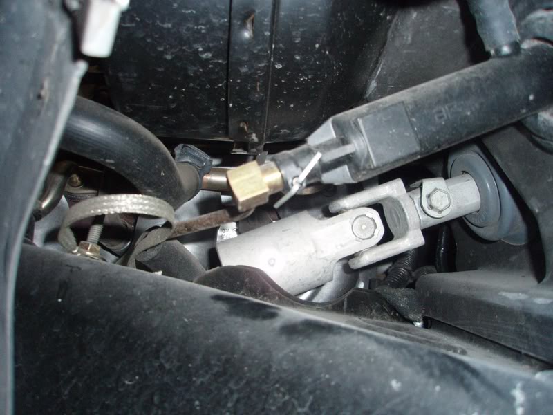
2. The nut gets removed with a 15mm socket. You don't have to hold the head of the bolt, as it has a locking tang that prevents it from turning. You can see this tang in the above photo. You have to turn the steering wheel to get the nut pointing at you for easy removal.
3. If you have Column Lock Bypass, you MUST reverse it to prevent a horrible disaster of having the wheel turned when it's disconnected from the car. Horrible. The reversal 's easy to do, since you have to remove all the dashboard stuff anyway, which allows ultra-easy access to the CLB connector. The reversal method is to turn the key to On, remove fuse 25, remove the CLB, reattach the original Column Lock connector, reinstall fuse 25, turn key Off and remove it. You should hear the lock do it's little buzz noise (you probably forgot what it sounded like). But wait until you do the two steps I've listed belowto make it super easy on yourself. Pull fuse 16 (airbag) while you're in the fuse block. In fact, do it early in the process to be safe. I'm not going into the airbag disarming procedure here, but you've been warned.
4. This has not been clearly mentioned in this thread so far: After you remove the knee bolster panel, you then have to remove the black plastic "tray" that is under the column. This tray contains the footwell light. To remove, you pull down gently on the front corners to extract the plastic trim fasteners holding those corners in place. It's easy to do, just pull straight down gently and firmly. Then, there is a third fastener in the back, and it's one of those flat metal retainers, very similar to what holds a brake rotor onto one wheel stud. I stuck a VERY large screwdriver between the plastic tray and the metal above it and twisted the screwdriver to force the clip down the stud a little ways. Then once it was a little loose, I could grab it with a needlenose and twist it off. This is a really dumb place for such a fastener, and as Indy300 has already mentioned, it's about the hardest thing to this whole job! The light unclips from behind and goes downward thru the tray. You can then manuver it out of the tray and get the tray completely out of your way. Or leave the the light in place and the tray on the floor, your choice.
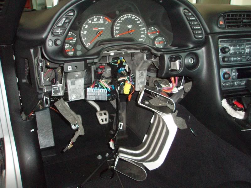
5. Now you have to remove the metal frame that holds the white styrofoam plastic knee bolster thingy. The column will not move rearward far enough or come out of the car without removing this thing. This is quickly done by removing the two small black screws on each side with the same 7mm socket you used to remove that wheelwell panel. The bolster drops out of the way and stays attached to the wires that are clipped to it, like this:
6. Now you can easily do the CLB reversal job with this stuff out of the way.
7. I recommend that you plan on taking the entire column out. It is MUCH easier to replace the sensor with the column out of the car. The sensor is a very tight fit to the steering shaft (by design) and would really be difficult to get it of the bottom of the shaft when it's in the car, IMO. All you have to do is detach the 5 or 6 electrical connectors (including the sensor connector down at the firewall) before you go to remove the column. Trust me on this--remove the connectors now so you can easily remove the entire wheel/column assembly when you get it unbolted.
8. The four nuts that hold the column in place are a 13mm socket. Remove the firewall nuts first, then one of the upper nuts, and then remove the final upper nut while you keep the column from dropping with your other hand. It's no heavy and won't come crashing down, but you'll want to support it.
9. Set a towel on the concrete so when you remove the column, you can set it down on the wheel without damaging anything.
10 After you get that last upper nut off, the whole column comes right out if you've gotten all the electrical connectors detached. Nothing to it. Super easy. Don't scratch your car with the end of the shaft as you triumphantly carry your column assembly to the towel!!
11. Replacing the sensor takes about 30 seconds.
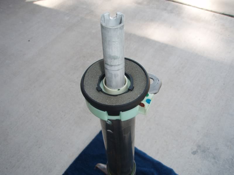
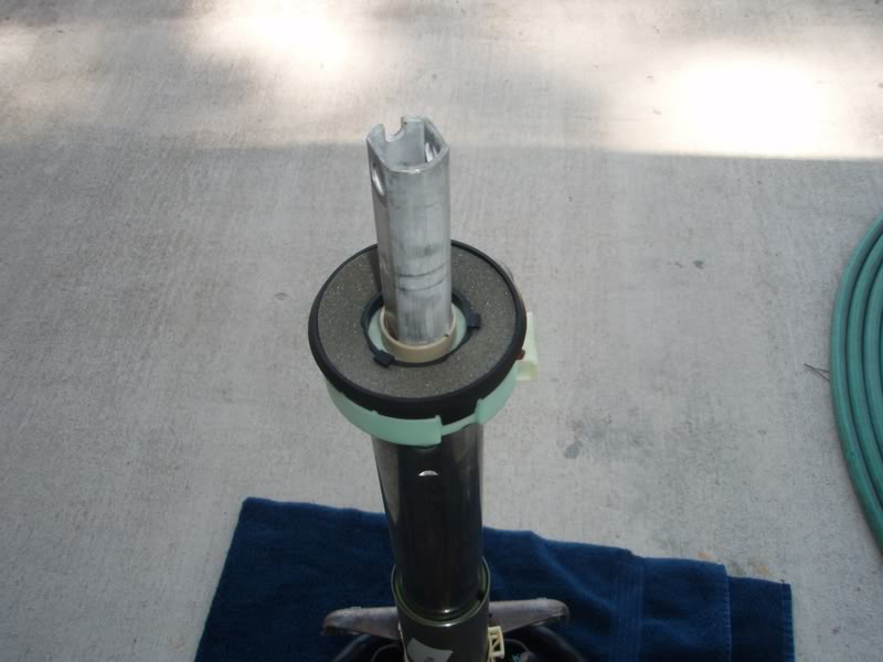
As removed from car, looking at the dust seal:
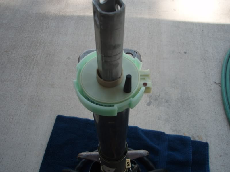
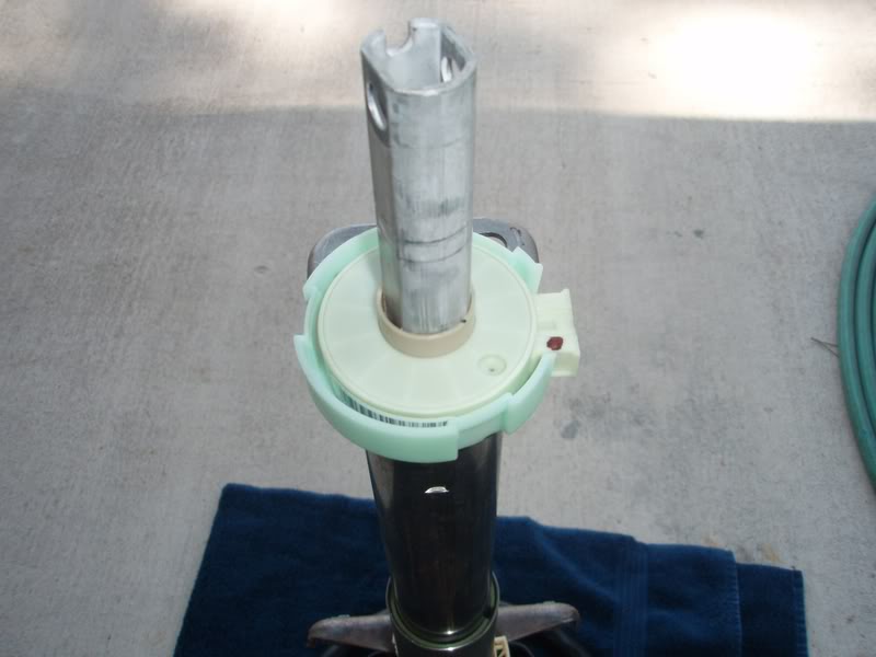
Dust seal is easily removed, showing sensor:
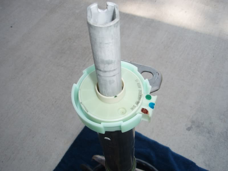
Sensor is held very snugly on the shaft by those many copper fingers that can be seen in the inside diameter, and by the green housing. This snug fit is why many of us are advising you to remove the column instead of working under the dash. You just lift a retainer tab or two on the green housing and it wiggles right up and off.
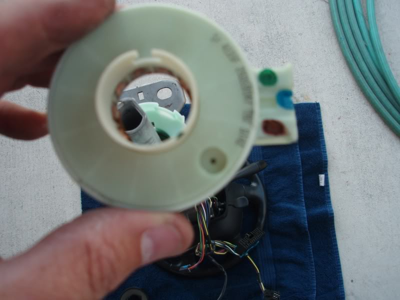
Pop the new sensor in. You'll know where it goes, so don't worry about screwing this up. It's ultra-obvious. Foolproof.
Now remove the pin. It's totally safe to do so at this point. It just pulls out with a little twist. Voila! Toss the famous pin in the trash....it's done its job.
Pop the dust seal back on and you're done with this operation.
12. So, now you put the column back in the car. You WILL dislodge the big grommet in the firewall, but don't worry about that at all. Use one of the upper nuts to loosely hold the column in place while you worry about getting the shaft joint to engage with the lower shaft stuff that's still in the car. It's easy, but a PITA. A second pair of hands would be great as you feed the shaft thru the firewall, but not mandatory.
13. Once you have the grommet on the shaft and that joint reengaged, loosely install the other three nuts that hold the column in place. Now you can get that grommet back into the firewall, all lined up. It just pushes in, nice and snug. I used a wood paint stirrer to work it all around from various directions, because even with the wheelwell opened up it's still difficult to get to. And THAT is why I think you should remove the wheel and the panel, as it's very difficult to see and reach from above. To me, that means it's very difficult to properly get it back in place.
14. At this point, it's a reversal of your work. If you damaged that damn tray retainer to get it off, you can either bend it back into shape, or use a washer with a piece of tubing on that stud to hold the tray in place. I straightened and salvaged the retainer, no problem, and the two front trim clips can be reused, no problem.
15. The shaft bolt likes to drop out of place when you turn the wheel to get the threads facing you to put the nut on. Ask me how I know. I used some duct tape to hold that bolt in place when I turned the wheel 180 degrees to get the nut on.
16. Don't go wild with tightening that shaft nut or the 4 nuts under the dash. They don't need to be some high torque value, just "tight". I didn't bother to look up the torque values in my manual because I noted during disassemby that they weren't very tight to begin with.
That's about it as far at my tips on doing this job. Follow the excellent information that is posted above me and use my added info, and you'll have no problems. When I was done, I fired the car up, had zero DIC messages and drove away to go slide around some corners with Active Handling back in action!!
But anyway, I just changed my sensor out after receiving the ususal 1287 and 1288 DIC messages that anyone reading this thread has seen, and here are my tips. The job took me about 4 hours (working and watching the wall-mount TV in the garage) but I could do it in 90 minutes now that I know exactly what to do and what the nut sizes are. It's technically very simple, but a real pain-in-the-*** as far as working under the dash area.
1. In my opinion, you should make it easy on yourself and remove the left front wheel and the black plastic access panel that is just behind it. That panel is held on by 8 or 9 sheetmetal screws that take a 7mm socket. It only takes minute to remove this panel, and it provides easy access to the otherwise extremely difficult-to-reach steering shaft bolt/nut. You'll drop the nut or the bolt and have to remove this panel anyway to find it, so do it now. You know how to remove a dang wheel, and you know how to unscrew a handful of sheetmetal screws, so do it!! You can see the head of the bolt thru the wheelwell in this picture.
2. The nut gets removed with a 15mm socket. You don't have to hold the head of the bolt, as it has a locking tang that prevents it from turning. You can see this tang in the above photo. You have to turn the steering wheel to get the nut pointing at you for easy removal.
3. If you have Column Lock Bypass, you MUST reverse it to prevent a horrible disaster of having the wheel turned when it's disconnected from the car. Horrible.
The reversal 's easy to do, since you have to remove all the dashboard stuff anyway, which allows ultra-easy access to the CLB connector. The reversal method is to turn the key to On, remove fuse 25, remove the CLB, reattach the original Column Lock connector, reinstall fuse 25, turn key Off and remove it. You should hear the lock do it's little buzz noise (you probably forgot what it sounded like). But wait until you do the two steps I've listed belowto make it super easy on yourself. Pull fuse 16 (airbag) while you're in the fuse block. In fact, do it early in the process to be safe. I'm not going into the airbag disarming procedure here, but you've been warned. 4. This has not been clearly mentioned in this thread so far: After you remove the knee bolster panel, you then have to remove the black plastic "tray" that is under the column. This tray contains the footwell light. To remove, you pull down gently on the front corners to extract the plastic trim fasteners holding those corners in place. It's easy to do, just pull straight down gently and firmly. Then, there is a third fastener in the back, and it's one of those flat metal retainers, very similar to what holds a brake rotor onto one wheel stud. I stuck a VERY large screwdriver between the plastic tray and the metal above it and twisted the screwdriver to force the clip down the stud a little ways. Then once it was a little loose, I could grab it with a needlenose and twist it off. This is a really dumb place for such a fastener, and as Indy300 has already mentioned, it's about the hardest thing to this whole job!
The light unclips from behind and goes downward thru the tray. You can then manuver it out of the tray and get the tray completely out of your way. Or leave the the light in place and the tray on the floor, your choice.5. Now you have to remove the metal frame that holds the white styrofoam plastic knee bolster thingy. The column will not move rearward far enough or come out of the car without removing this thing. This is quickly done by removing the two small black screws on each side with the same 7mm socket you used to remove that wheelwell panel. The bolster drops out of the way and stays attached to the wires that are clipped to it, like this:
6. Now you can easily do the CLB reversal job with this stuff out of the way.
7. I recommend that you plan on taking the entire column out. It is MUCH easier to replace the sensor with the column out of the car. The sensor is a very tight fit to the steering shaft (by design) and would really be difficult to get it of the bottom of the shaft when it's in the car, IMO. All you have to do is detach the 5 or 6 electrical connectors (including the sensor connector down at the firewall) before you go to remove the column. Trust me on this--remove the connectors now so you can easily remove the entire wheel/column assembly when you get it unbolted.
8. The four nuts that hold the column in place are a 13mm socket. Remove the firewall nuts first, then one of the upper nuts, and then remove the final upper nut while you keep the column from dropping with your other hand. It's no heavy and won't come crashing down, but you'll want to support it.
9. Set a towel on the concrete so when you remove the column, you can set it down on the wheel without damaging anything.
10 After you get that last upper nut off, the whole column comes right out if you've gotten all the electrical connectors detached. Nothing to it. Super easy. Don't scratch your car with the end of the shaft as you triumphantly carry your column assembly to the towel!!
11. Replacing the sensor takes about 30 seconds.
As removed from car, looking at the dust seal:
Dust seal is easily removed, showing sensor:
Sensor is held very snugly on the shaft by those many copper fingers that can be seen in the inside diameter, and by the green housing. This snug fit is why many of us are advising you to remove the column instead of working under the dash. You just lift a retainer tab or two on the green housing and it wiggles right up and off.
Pop the new sensor in. You'll know where it goes, so don't worry about screwing this up. It's ultra-obvious. Foolproof.
Now remove the pin. It's totally safe to do so at this point. It just pulls out with a little twist. Voila! Toss the famous pin in the trash....it's done its job.
Pop the dust seal back on and you're done with this operation.
12. So, now you put the column back in the car. You WILL dislodge the big grommet in the firewall, but don't worry about that at all. Use one of the upper nuts to loosely hold the column in place while you worry about getting the shaft joint to engage with the lower shaft stuff that's still in the car. It's easy, but a PITA. A second pair of hands would be great as you feed the shaft thru the firewall, but not mandatory.
13. Once you have the grommet on the shaft and that joint reengaged, loosely install the other three nuts that hold the column in place. Now you can get that grommet back into the firewall, all lined up. It just pushes in, nice and snug. I used a wood paint stirrer to work it all around from various directions, because even with the wheelwell opened up it's still difficult to get to. And THAT is why I think you should remove the wheel and the panel, as it's very difficult to see and reach from above. To me, that means it's very difficult to properly get it back in place.
14. At this point, it's a reversal of your work. If you damaged that damn tray retainer to get it off, you can either bend it back into shape, or use a washer with a piece of tubing on that stud to hold the tray in place. I straightened and salvaged the retainer, no problem, and the two front trim clips can be reused, no problem.
15. The shaft bolt likes to drop out of place when you turn the wheel to get the threads facing you to put the nut on. Ask me how I know.
I used some duct tape to hold that bolt in place when I turned the wheel 180 degrees to get the nut on. 16. Don't go wild with tightening that shaft nut or the 4 nuts under the dash. They don't need to be some high torque value, just "tight". I didn't bother to look up the torque values in my manual because I noted during disassemby that they weren't very tight to begin with.
That's about it as far at my tips on doing this job. Follow the excellent information that is posted above me and use my added info, and you'll have no problems. When I was done, I fired the car up, had zero DIC messages and drove away to go slide around some corners with Active Handling back in action!!
Last edited by Tracy; 04-01-2008 at 09:11 AM.
The following users liked this post:
StandardZ (01-09-2021)
03-31-2008, 07:24 AM
#36
Night Owl for life

Member Since: Nov 2003
Location: Bugs Bunny should'a made a left turn here
Posts: 23,198
Received 3,246 Likes
on
1,668 Posts
wow there's tons of awesome info here. i have been experiencing code 1286, "steering sensor bias malfunction". would this code require the same fix as shown in this thread?
03-31-2008, 10:32 AM
#38
Safety Car

 04-29-2008, 02:03 PM
#39
Night Owl for life
Member Since: Nov 2003
Location: Bugs Bunny should'a made a left turn here
Posts: 23,198
Received 3,246 Likes
on
1,668 Posts
does anyone have the part number for the SWPS? the one up top didnt give me anything.
i looked thru the catalogs on gmpartshouse but i couldnt find it. it's for a 2000 if that matters.
thanks.
i looked thru the catalogs on gmpartshouse but i couldnt find it. it's for a 2000 if that matters.
thanks.
04-29-2008, 03:57 PM
#40
Tech Contributor
Member Since: Dec 2003
Location: Horncastle Lincolnshire, England
Posts: 19,384
Likes: 0
Received 79 Likes
on
61 Posts
2023 C5 of the Year Finalist - Unmodified

Great write up guys
I've had the 1287 for a while now and I know I'm going to have to bite the bullet soon
Thanks again
I've had the 1287 for a while now and I know I'm going to have to bite the bullet soon
Thanks again