
Headlight Control Module Bad...Why?
 11-12-2011, 03:23 PM
#1
Melting Slicks

Thread Starter

I did some diagnostic work on my '98 C5. My problem was the LH headlight wouldn't go up or down. The RH is fine. I recall some issues with delayed opening, finally it just wouldn't open. I recall when I washed the car the RH headlamp opened on it's own. After that the LH wouldn't open or close. I removed the headlamp connector at the LH capsule and applied 12V directly to the motor terminals, then reversed them. The door opened and closed with no problem. I removed the headlamp control module connectors and brought them into the engine compartment (barely reached). Check voltage and ground to the module, tested ok. Removed the control module and it smelt burnt. Cover on module was separating from from case. I pried it off and removed the circuit board. Definitely burnt components on the board. So my question is WHY? What caused this to happen. Was the cover already separating and when I washed the car the water damaged the components? I know there is power applied to the module all the time. Dealer want's over $300 for this part. I don't know what external issues may have caused this to fail. I'm just inquiring since I don't want to see the new module fail. Any comments are appreciated. I'll try to post a pic of the opened module.
Art
Art
 11-12-2011, 04:13 PM
#2
Tech Contributor


Member Since: Dec 1999
Location: Anthony TX
Posts: 32,736
Received 2,180 Likes
on
1,583 Posts
CI 6,7,8,9,11 Vet
St. Jude Donor '08

Art
They do fail!! Some just quit, some draw excessive current and kill the battery. I have NOT seen many failures. IMHO it was just the modules time to go. Purchasing a NEW module and making SURE that all the connections are clean and water tight and the pins in the connectors are not damaged, spread or corroded, everything should be fine.
Can you take some picture of the inside of that module and post them??
Thanks
Bill
12-18-2011, 06:47 PM
#3
Melting Slicks
Thread Starter
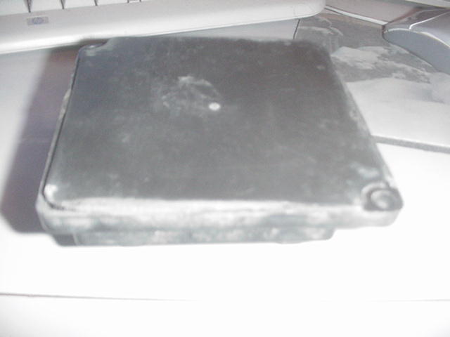
It's been a few weeks since I replaced the module with a used one which works perfectly now. Here's a couple of pics of the circuit boarda and leaking housing. The housing pic is bad but the closest edge has separated from the housing allowing water inside. You can see where a component overheated. Probably due to water and shorting out.
Sorry it took so long.

Sorry it took so long.
Art
They do fail!! Some just quit, some draw excessive current and kill the battery. I have NOT seen many failures. IMHO it was just the modules time to go. Purchasing a NEW module and making SURE that all the connections are clean and water tight and the pins in the connectors are not damaged, spread or corroded, everything should be fine.
Can you take some picture of the inside of that module and post them??
Thanks
Bill
They do fail!! Some just quit, some draw excessive current and kill the battery. I have NOT seen many failures. IMHO it was just the modules time to go. Purchasing a NEW module and making SURE that all the connections are clean and water tight and the pins in the connectors are not damaged, spread or corroded, everything should be fine.
Can you take some picture of the inside of that module and post them??
Thanks
Bill
Last edited by MrRenoman; 12-18-2011 at 06:49 PM. Reason: Arrange text
The following users liked this post:
gpruitt54 (09-30-2016)
12-18-2011, 10:23 PM
#4
Melting Slicks

It's been a few weeks since I replaced the module with a used one which works perfectly now. Here's a couple of pics of the circuit boarda and leaking housing. The housing pic is bad but the closest edge has separated from the housing allowing water inside. You can see where a component overheated. Probably due to water and shorting out.
Sorry it took so long.

Sorry it took so long.
12-18-2011, 10:32 PM
#5
Tech Contributor

Other than improving the seal, how would you have designed the circuit board differently?
12-19-2011, 09:50 AM
#6
Safety Car

 12-19-2011, 10:29 AM
#7
Safety Car
I would have used glass/epoxy board material and placed some heat sinking on the power devices. The power device on the right looks like it became too hot and burned out. From what I've read on this design, the module reads the motor current and turns the motor power off when the stops are hit instead of using limit switches.
12-19-2011, 10:48 AM
#8
Tech Contributor
I would have used glass/epoxy board material and placed some heat sinking on the power devices. The power device on the right looks like it became too hot and burned out. From what I've read on this design, the module reads the motor current and turns the motor power off when the stops are hit instead of using limit switches.
12-20-2011, 05:24 PM
#9
Safety Car
I'm glad you posted this, I took the module out of my car as the headlights are being worked on and was surprised what it looked like.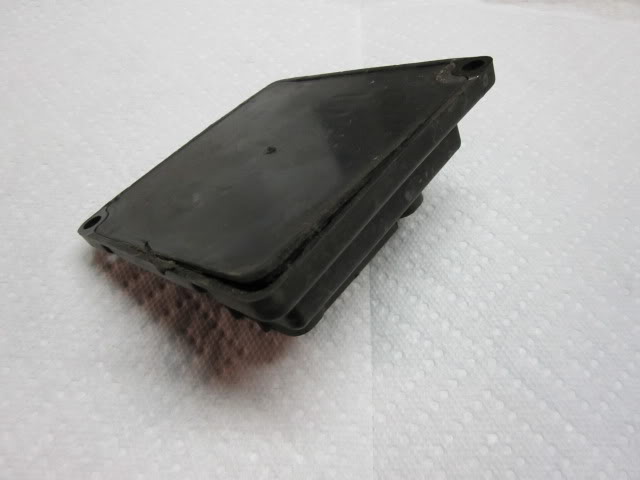 The back of the module is separated!
To seal the module they used that all purpose GM tar, notice the extra on the circuit board.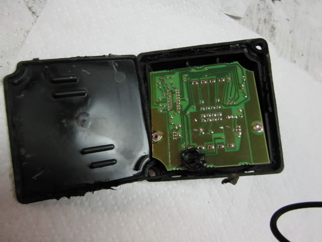
Since the module is attached at two corners, stress can pop the back cover off at the other corners.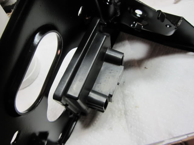
The circuit board was burned a little as seen here.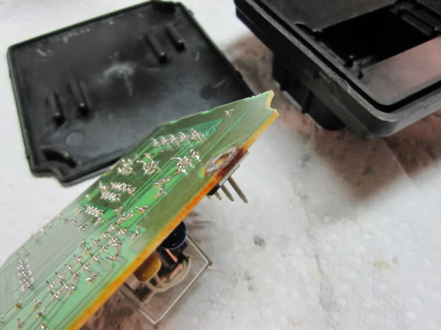
I cleaned all the tar off the plastic housing. The rivets were drilled out of the two power devices and the green coating was cleaned off the copper in that area. Some scrap brass was soldered on the circuit board and a wire was soldered to that.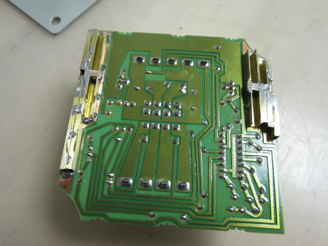
The other end of the wire (10 gage stranded) was connected to the power device with silver epoxy. This should provide more heat sinking than the little copper traces did. The 9 connector terminals were masked then both sides of the board were sprayed with clear paint for extra moisture protection.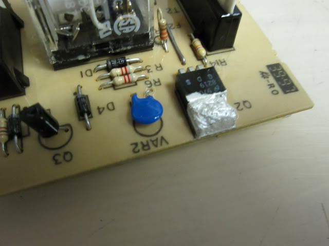
Here's the parts to be assembled using Goop adhesive.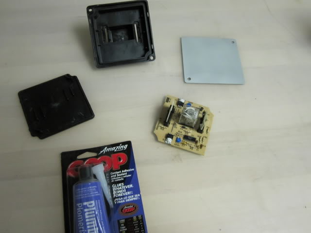
A little Goop was added around the two connectors before the circuit board was placed in the main housing then the trench around the board was filled with Goop and the back was snapped into place.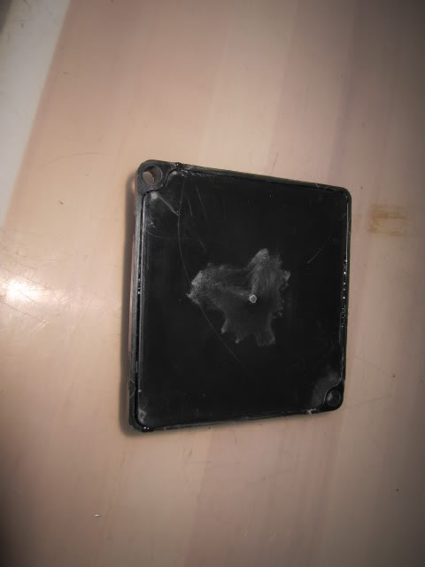
An aluminum plate was made and Gooped to the assembly, clamps are now holding all this together until the adhesive cures.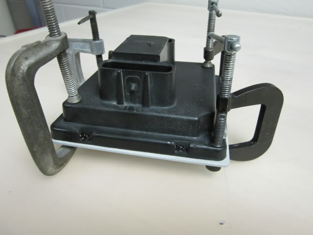
Tonight the module will be plugged back into the car to see if it still works. The Goop should keep the assembly together and dry, the aluminum plate should spread the stress over the whole back to keep the corners from popping out and the brass should keep the power devices cooler. I'm glad this was checked before it failed, who wants to spend $300 for another module sealed with tar.
The back of the module is separated! To seal the module they used that all purpose GM tar, notice the extra on the circuit board.
Since the module is attached at two corners, stress can pop the back cover off at the other corners.
The circuit board was burned a little as seen here.
I cleaned all the tar off the plastic housing. The rivets were drilled out of the two power devices and the green coating was cleaned off the copper in that area. Some scrap brass was soldered on the circuit board and a wire was soldered to that.
The other end of the wire (10 gage stranded) was connected to the power device with silver epoxy. This should provide more heat sinking than the little copper traces did. The 9 connector terminals were masked then both sides of the board were sprayed with clear paint for extra moisture protection.
Here's the parts to be assembled using Goop adhesive.
A little Goop was added around the two connectors before the circuit board was placed in the main housing then the trench around the board was filled with Goop and the back was snapped into place.
An aluminum plate was made and Gooped to the assembly, clamps are now holding all this together until the adhesive cures.
Tonight the module will be plugged back into the car to see if it still works. The Goop should keep the assembly together and dry, the aluminum plate should spread the stress over the whole back to keep the corners from popping out and the brass should keep the power devices cooler. I'm glad this was checked before it failed, who wants to spend $300 for another module sealed with tar.
The following 2 users liked this post by Fast one:
Sam Handwich (01-21-2022),
TXWMH (03-14-2022)
02-23-2012, 06:18 AM
#10
3rd Gear


Member Since: Feb 2012
Posts: 3
Likes: 0
Received 0 Likes
on
0 Posts
Thanks for that info Fast One.
I'm having a problem with my module. It all started a few months ago when the LH headlight stopped working. I did all the checks and determined that it was the module.
I received a replacement from Corvette Central only to find a new fault - the headlights would close, but not open! Checked everything again, but it seemed to be the module. Sent it back for replacement.
In the meantime, I found a 'new' module for sale here in the UK. I installed that one and guess what... only the LH headlight operates!
I've stripped my old module and the new one. In the old one, the power transistor Q1 has burnt. In the new one, there are no signs of faults.
I'm guessing the IC is faulty, but I can't identify it. I've looked for equivalents, but can't find anything. The IC on the old module is labelled:
16511949
CS8931H
The new one is:
16512455
UEX00513
The number starting with 165XXXXX looks like a GM part number.
My question is, does anyone know what the IC is? In the electrical schematics, it's just shown as a solid state switch.
Cheers
David
Cornwall, England
02-23-2012, 08:28 AM
#12
3rd Gear
Member Since: Feb 2012
Posts: 3
Likes: 0
Received 0 Likes
on
0 Posts
02-23-2012, 09:17 AM
#13
Tech Contributor
Member Since: Dec 2006
Location: Van Buren Arkansas
Posts: 10,962
Likes: 0
Received 26 Likes
on
25 Posts
Wounded Warrior Escort '11

It'll be about two weeks before I get back but if I can repair this, you can have it for free. Its got issues with the passenger headlamp not always coming up. I put one in that I bought off someone or ebay and its working just fine, so this extra has issues but I'll look into it. If you want it as-is, you can have it now but its up to you to repair it.
02-23-2012, 10:00 AM
#14
Tech Contributor
Member Since: Dec 1999
Location: Anthony TX
Posts: 32,736
Received 2,180 Likes
on
1,583 Posts
CI 6,7,8,9,11 Vet
St. Jude Donor '08
See how a single post can turn into a C5 MONEY SAVING idea!!
Thanks everyone who contributed and added pics and ideas!
Bill
Thanks everyone who contributed and added pics and ideas!
Bill
02-23-2012, 10:13 AM
#15
3rd Gear
Member Since: Feb 2012
Posts: 3
Likes: 0
Received 0 Likes
on
0 Posts
It'll be about two weeks before I get back but if I can repair this, you can have it for free. Its got issues with the passenger headlamp not always coming up. I put one in that I bought off someone or ebay and its working just fine, so this extra has issues but I'll look into it. If you want it as-is, you can have it now but its up to you to repair it.
Hi
I've been doing some checking... I opened the module I bought in the UK and discovered that it has an identical board inside to the one in jcgunn's & Fast One's pics.
On further investigation, it seems that although in identical outer cases, the internals are different between the C4 & C5 modules. This may explain why the C5 one doesn't work on my C4!
Many thanks for your kind offer, but I will have to see if I can get a specific C4 module. The seller of the C5 one I bought in the UK has agreed to take it back as he advertised it as C4.
Thanks again.
Cheers
David
09-26-2016, 01:21 PM
#17
Burning Brakes

The control module on the passenger recently started ticking. Does that mean it is gone or is about to go? As of now, my headlights go up, but will not go down unless I flick the High beams on.
09-27-2016, 09:01 AM
#18
Safety Car
If HID lights were added they can cause the problem of the motors not closing unless the high beams are selected, this is due to the reduced current draw of the more efficient HIDs. Most owners add power resistors to increase the current draw so the lights will open and close as they did with the old lamps. Did you remove the control module and check it for defects as seen in the above photos such as a warped cover that can let in water?
09-30-2016, 11:31 AM
#20
Burning Brakes
It seems that most everyone buys these things used. I got the shock of my life when the dealer told me these modules cost $675.00 new.
The guy at the parts desk recommend finding a used one at the bone yard or Ebay. My unit is ticking. It is not getting warm. It's only making a ticking sound.
The guy at the parts desk recommend finding a used one at the bone yard or Ebay. My unit is ticking. It is not getting warm. It's only making a ticking sound.